TLE7186F
System IC for B6 motor drives
Data Sheet
Rev. 1.2, 2016-01-28
Automotive Power
�TLE7186F
Table of Contents
Table of Contents
Table of Contents . . . . . . . . . . . . . . . . . . . . . . . . . . . . . . . . . . . . . . . . . . . . . . . . . . . . . . . . . . . . . . . . 2
1
Overview . . . . . . . . . . . . . . . . . . . . . . . . . . . . . . . . . . . . . . . . . . . . . . . . . . . . . . . . . . . . . . . . . . . . . . . 4
2
Block Diagram . . . . . . . . . . . . . . . . . . . . . . . . . . . . . . . . . . . . . . . . . . . . . . . . . . . . . . . . . . . . . . . . . . . 5
3
3.1
3.2
Pin Configuration . . . . . . . . . . . . . . . . . . . . . . . . . . . . . . . . . . . . . . . . . . . . . . . . . . . . . . . . . . . . . . . . 6
Pin Assignment TLE7186F . . . . . . . . . . . . . . . . . . . . . . . . . . . . . . . . . . . . . . . . . . . . . . . . . . . . . . . . . . 6
Pin Definitions and Functions . . . . . . . . . . . . . . . . . . . . . . . . . . . . . . . . . . . . . . . . . . . . . . . . . . . . . . . . 7
4
4.1
4.2
4.3
4.4
General Product Characteristics . . . . . . . . . . . . . . . . . . . . . . . . . . . . . . . . . . . . . . . . . . . . . . . . . . . . 9
Absolute Maximum Ratings . . . . . . . . . . . . . . . . . . . . . . . . . . . . . . . . . . . . . . . . . . . . . . . . . . . . . . . . . 9
Functional Range . . . . . . . . . . . . . . . . . . . . . . . . . . . . . . . . . . . . . . . . . . . . . . . . . . . . . . . . . . . . . . . . 10
Thermal Resistance . . . . . . . . . . . . . . . . . . . . . . . . . . . . . . . . . . . . . . . . . . . . . . . . . . . . . . . . . . . . . . 11
Default State of Inputs . . . . . . . . . . . . . . . . . . . . . . . . . . . . . . . . . . . . . . . . . . . . . . . . . . . . . . . . . . . . 11
5
5.1
5.2
5.3
5.4
5.5
MOSFET Driver . . . . . . . . . . . . . . . . . . . . . . . . . . . . . . . . . . . . . . . . . . . . . . . . . . . . . . . . . . . . . . . . .
Inputs and Dead Time . . . . . . . . . . . . . . . . . . . . . . . . . . . . . . . . . . . . . . . . . . . . . . . . . . . . . . . . . . . .
Output Stages . . . . . . . . . . . . . . . . . . . . . . . . . . . . . . . . . . . . . . . . . . . . . . . . . . . . . . . . . . . . . . . . . . .
Bootstrap Principle . . . . . . . . . . . . . . . . . . . . . . . . . . . . . . . . . . . . . . . . . . . . . . . . . . . . . . . . . . . . . . .
Currents at SH pins . . . . . . . . . . . . . . . . . . . . . . . . . . . . . . . . . . . . . . . . . . . . . . . . . . . . . . . . . . . . . .
Electrical Characteristics . . . . . . . . . . . . . . . . . . . . . . . . . . . . . . . . . . . . . . . . . . . . . . . . . . . . . . . . . .
6
6.1
Shunt Signal Conditioning . . . . . . . . . . . . . . . . . . . . . . . . . . . . . . . . . . . . . . . . . . . . . . . . . . . . . . . . 16
Electrical Characteristics . . . . . . . . . . . . . . . . . . . . . . . . . . . . . . . . . . . . . . . . . . . . . . . . . . . . . . . . . . 16
7
7.1
5 V Low Drop Voltage Regulator . . . . . . . . . . . . . . . . . . . . . . . . . . . . . . . . . . . . . . . . . . . . . . . . . . . 18
Electrical Characteristics . . . . . . . . . . . . . . . . . . . . . . . . . . . . . . . . . . . . . . . . . . . . . . . . . . . . . . . . . . 18
8
8.1
8.2
8.3
8.4
Interface, VDH Switch and INH Digital Output . . . . . . . . . . . . . . . . . . . . . . . . . . . . . . . . . . . . . . . .
PWM Interface (IFMA) . . . . . . . . . . . . . . . . . . . . . . . . . . . . . . . . . . . . . . . . . . . . . . . . . . . . . . . . . . . .
VDHS Switch . . . . . . . . . . . . . . . . . . . . . . . . . . . . . . . . . . . . . . . . . . . . . . . . . . . . . . . . . . . . . . . . . . .
Digital Output INHD . . . . . . . . . . . . . . . . . . . . . . . . . . . . . . . . . . . . . . . . . . . . . . . . . . . . . . . . . . . . . .
Electrical Characteristics . . . . . . . . . . . . . . . . . . . . . . . . . . . . . . . . . . . . . . . . . . . . . . . . . . . . . . . . . .
21
21
22
22
22
9
9.1
9.2
9.2.1
9.2.2
9.2.3
9.2.4
9.2.5
9.2.6
9.2.7
9.2.8
9.2.9
9.2.10
9.2.11
9.2.12
9.2.13
9.2.14
9.2.15
9.3
Description of Modes, Protection and Diagnostic Functions . . . . . . . . . . . . . . . . . . . . . . . . . . .
Description of modes . . . . . . . . . . . . . . . . . . . . . . . . . . . . . . . . . . . . . . . . . . . . . . . . . . . . . . . . . . . . .
Protection and Diagnosis Functions . . . . . . . . . . . . . . . . . . . . . . . . . . . . . . . . . . . . . . . . . . . . . . . . . .
Over Temperature Shut Down (OTSD) . . . . . . . . . . . . . . . . . . . . . . . . . . . . . . . . . . . . . . . . . . . . . .
Over Temperature Prewarning (OTPW) . . . . . . . . . . . . . . . . . . . . . . . . . . . . . . . . . . . . . . . . . . . . .
Analog Temperature Monitoring . . . . . . . . . . . . . . . . . . . . . . . . . . . . . . . . . . . . . . . . . . . . . . . . . . .
VS Under Voltage Lockout (VS_UVLO) . . . . . . . . . . . . . . . . . . . . . . . . . . . . . . . . . . . . . . . . . . . . .
VDD Under Voltage Diagnosis (VDD_UVD) . . . . . . . . . . . . . . . . . . . . . . . . . . . . . . . . . . . . . . . . . .
VDD Under Voltage Shut Down (VDD_UVSD) . . . . . . . . . . . . . . . . . . . . . . . . . . . . . . . . . . . . . . . .
VREG Under Voltage Diagnosis (VREG_UVD) . . . . . . . . . . . . . . . . . . . . . . . . . . . . . . . . . . . . . . . .
VREG Under Voltage Shut Down (VREG_UVSD) . . . . . . . . . . . . . . . . . . . . . . . . . . . . . . . . . . . . .
IOV and VDH Over Voltage Shut Down (IOV_OVSD, VDH_OVSD) . . . . . . . . . . . . . . . . . . . . . . . .
Dead Time and Shoot Through Protection . . . . . . . . . . . . . . . . . . . . . . . . . . . . . . . . . . . . . . . . . . .
Short Circuit Protection (SCP) . . . . . . . . . . . . . . . . . . . . . . . . . . . . . . . . . . . . . . . . . . . . . . . . . . . . .
SCDL Pin Open Detection (SCDL_open) . . . . . . . . . . . . . . . . . . . . . . . . . . . . . . . . . . . . . . . . . . . .
Over Current Shut Down (OCSD) . . . . . . . . . . . . . . . . . . . . . . . . . . . . . . . . . . . . . . . . . . . . . . . . . .
VDD Current Limitation . . . . . . . . . . . . . . . . . . . . . . . . . . . . . . . . . . . . . . . . . . . . . . . . . . . . . . . . . .
Passive Gxx Clamping . . . . . . . . . . . . . . . . . . . . . . . . . . . . . . . . . . . . . . . . . . . . . . . . . . . . . . . . . . .
ERR Pin . . . . . . . . . . . . . . . . . . . . . . . . . . . . . . . . . . . . . . . . . . . . . . . . . . . . . . . . . . . . . . . . . . . . . . .
24
24
27
27
27
27
28
28
28
28
29
29
29
30
30
30
30
30
30
Data Sheet
2
12
12
12
13
13
13
Rev. 1.2, 2016-01-28
�TLE7186F
Table of Contents
9.4
Electrical Characteristics . . . . . . . . . . . . . . . . . . . . . . . . . . . . . . . . . . . . . . . . . . . . . . . . . . . . . . . . . . 32
10
10.1
Phase voltage feedback . . . . . . . . . . . . . . . . . . . . . . . . . . . . . . . . . . . . . . . . . . . . . . . . . . . . . . . . . . 35
Electrical Characteristics . . . . . . . . . . . . . . . . . . . . . . . . . . . . . . . . . . . . . . . . . . . . . . . . . . . . . . . . . . 35
11
Application Description . . . . . . . . . . . . . . . . . . . . . . . . . . . . . . . . . . . . . . . . . . . . . . . . . . . . . . . . . . 36
12
Package Outlines . . . . . . . . . . . . . . . . . . . . . . . . . . . . . . . . . . . . . . . . . . . . . . . . . . . . . . . . . . . . . . . 37
13
Revision History . . . . . . . . . . . . . . . . . . . . . . . . . . . . . . . . . . . . . . . . . . . . . . . . . . . . . . . . . . . . . . . . 38
Data Sheet
3
Rev. 1.2, 2016-01-28
�System IC for B6 motor drives
1
TLE7186F
Overview
Features
•
•
•
•
•
•
•
•
•
•
•
•
•
•
•
•
•
•
•
Drives 6 N-Channel Power MOSFETs
Integrated 5V Vreg-Controller to power μC
Integrated switch for VDH voltage
Separate control input for each MOSFET
Adjustable dead time
Shoot through protection
Analog adjustable Short Circuit Protection levels
Low quiescent current mode
1 bit diagnosis ERR
Over Temperature shut down and analog temperature output
Over Temperature pre-warning
Under Voltage shut down
Adjustable Over Voltage shut down
Current sense OpAmp
Over current shut down based on Current sense OpAmp, fixed shut down level
0 …94% duty cycle at 25 kHz PWM frequency
Digital phase voltage feedback
Green Product (RoHS compliant)
AEC Qualified
PG-VQFN-48
Description
The TLE7186F is a system IC for Brushless Motor Control. It incorporates a voltage supply for a μC, a bridge driver
for a B6 configuration, an application typical PWM interface and some other smaller features. Target is to reduce
the number of discrete components in typical BLDC automotive applications and give enough flexibility for custom
specific adaptations.
It works with 3-phase motors and brush DC motors. Its exposed pad package allows the usage even at high
ambient temperatures.
Type
Package
Marking
TLE7186F
PG-VQFN-48
TLE7186F
Data Sheet
4
Rev. 1.2, 2016-01-28
�TLE7186F
Block Diagram
2
Block Diagram
VS
VDD
GND
___ ____
INH INHD
VREG
switch
5V voltage
regulator
BH1
SH1
Digital phase
voltage feedback
W_fb
Floating HS driver
Short circuit detection
SH2
SH3
IOV
____
ERR
____
RGS
Diagnostic logic
Under voltage
Over voltage
Overtemperature
Short circuit
Reset
Over current
SCDL
TEMP
IFuC
Interface
IFMA
DT
Floating LS driver
Short circuit detection
L
E
V
E
L
GL1
BH2
Floating HS driver
Short circuit detection
GH2
SH2
Floating LS driver
Short circuit detection
Input control
Shoot through
protection
dead time
IL2
___
IH2
GH1
SH1
S
H
I
F
T
E
R
IL1
___
IH1
VDH
VREG
U_fb
V_fb
VDHS
GL2
BH3
Floating HS driver
Short circuit detection
GH3
SH3
IL3
___
IH3
Floating LS driver
Short circuit detection
AGND
GL3
SL
ISP
ISN
OCTH
GND
ISO
Figure 1
Data Sheet
Block Diagram
5
Rev. 1.2, 2016-01-28
�TLE7186F
Pin Configuration
3
Pin Configuration
3.1
Pin Assignment TLE7186F
____
RGS
____
ERR
GND
36
35
34
33
VDD
32
31
V_fb
30
GND
IOV
29
W_fb
28
27
VDH
26
25
37
24
BH1
IL1
38
23
GH1
___
IH2
39
22
SH1
IL2
40
21
GL1
___
IH3
41
20
BH2
IL3
42
19
GH2
AGND
43
18
SH2
ISN
44
17
GL2
ISP
45
16
BH3
ISO
46
15
GH3
____
INHD
47
14
SH3
48
13
GL3
TLE 7186 F
Topview
1
2
3
4
IFMA
GND
___
INH
Data Sheet
TEMP
N.C
___
IH1
IFuC
Figure 2
GND
5
6
7
VS
VDHS
8
VREG
U_fb
9
10
SCDL
NC
11
12
DT
SL
GND
Pin Configuration
6
Rev. 1.2, 2016-01-28
�TLE7186F
Pin Configuration
3.2
Pin
Pin Definitions and Functions
Symbol
Function
5
VS
Supply Pin
7
VREG
Output of supply for driver output stages - connect to capacitor
31
VDD
Output of 5V supply for μC - connect to capacitor
2
INH
Input pin wake up the complete system IC
47
INHD
Digital output 5V for INH state (high when INH is high)
4
VDHS
Switched output of VDH voltage; switch open in sleep mode
33
TEMP
Output pin for analog temperature signal
36
RGS
Reset and Go-to-Sleep input pin for reset of error registers, set HIGH to avoid to goto-sleep
38
IL1
Input for low side switch 1 (active high)
37
IH1
Input for high side switch 1 (active low)
40
IL2
Input for low side switch 2 (active high)
39
IH2
Input for high side switch 2 (active low)
42
IL3
Input for low side switch 3(active high)
41
IH3
Input for high side switch 3(active low)
11
DT
Input pin for adjustable dead time function, connect to GND via resistor
9
SCDL
Analog input pin for adjustable Short Circuit Detection function, connect to voltage
divider
28
IOV
Input pin for Over Voltage detection.
34
ERR
Open drain error output
25
VDH
Voltage input common drain high side for short circuit detection
24
BH1
Pin for + terminal of the bootstrap capacitor of phase 1
23
GH1
Output pin for gate of high side MOSFET 1
22
SH1
Pin for source connection of high side MOSFET 1
21
GL1
Output pin for gate of low side MOSFET 1
20
BH2
Pin for + terminal of the bootstrap capacitor of phase 2
19
GH2
Output pin for gate of high side MOSFET 2
18
SH2
Pin for source connection of high side MOSFET 2
17
GL2
Output pin for gate of low side MOSFET 2
16
BH3
Pin for + terminal of the bootstrap capacitor of phase 3
15
GH3
Output pin for gate of high side MOSFET 3
14
SH3
Pin for source connection of high side MOSFET 3
13
GL3
Output pin for gate of low side MOSFET 3
10
SL
Pin for common source connection of low side MOSFETs
44
ISN
Input for OpAmp - terminal
45
ISP
Input for OpAmp + terminal
46
ISO
Output of OpAmp
43
AGND
Analog GND for Opamp and analog temperature output
3
IFMA
Interface to master ECU (used for wake up)
48
IFuC
Interface to μC
Data Sheet
7
Rev. 1.2, 2016-01-28
�TLE7186F
Pin Configuration
Pin
Symbol
Function
6
U_fb
Digital phase voltage feedback output of SH1
29
V_fb
Digital phase voltage feedback output of SH2
27
W_fb
Digital phase voltage feedback output of SH3
1
GND
Ground pin
12
GND
Ground pin
26
GND
Ground pin
32
GND
Ground pin
35
GND
Ground pin
8
NC
connect to GND
30
NC
connect to GND
Exposed pad to be connected to GND
Data Sheet
8
Rev. 1.2, 2016-01-28
�TLE7186F
General Product Characteristics
4
General Product Characteristics
4.1
Absolute Maximum Ratings
Absolute Maximum Ratings 1)
Tj = -40 °C to +150 °C; all voltages with respect to ground, positive current flowing into pin (unless otherwise
specified)
Pos.
Parameter
Symbol
Limit Values
Unit
Conditions
Min.
Max.
-0.3
45
V
–
-6.0
45
V
-3.0
45
V
R >= 10k:
RVS >= 4.7:;
-3.0
45
V
Voltages
4.1.1
Voltage range at VS, IFMA, INH, IOV
4.1.2
Voltage range at IFMA, INH
4.1.3
Voltage range at VS
VVS1
VIFMA
VVS2
4.1.4
Voltage range at VS
VVS3
60s, 5x;
RVS >= 2.0:�;
200ms, 5x;
VVREG
VVDHx
VVDH1
-0.3
Voltage range at IHx, ILx, RGS, ERR,
IFuC, TEMP, DT, VDD, ISO, INHD,
SCDL, U_fb, V_fb, W_fb
4.1.9
Voltage range at ISP, ISN
4.1.10
Voltage difference between ISP and ISN VOPD
4.1.11
Voltage range at BHx
4.1.12
Voltage range at GHx
4.1.13
Voltage range at GHx
4.1.14
Voltage range at SHx
4.1.5
Voltage range at VREG output
4.1.6
Voltage range at VDH, VDHS
4.1.7
Voltage range at VDH
4.1.8
4.1.15
Voltage range at SHx
4.1.16
Voltage range at GLx
4.1.17
Voltage range at GLx
4.1.18
Voltage range at SL
4.1.19
Voltage range at SL
4.1.20
Voltage difference Gxx-Sxx
4.1.21
Voltage difference BHx-SHx
4.1.22
Minimum bootstrap capacitor CBS
4.1.23
Minimum buffer capacitor CVREG
4.1.24
Maximum load capacitance for voltage
feedback output X_FB
15
V
-0.3
55
V
–
-3.0
55
V
With RVDH
>=10:; 60s, 5x;
Tj
很抱歉,暂时无法提供与“TLE7186FXUMA1”相匹配的价格&库存,您可以联系我们找货
免费人工找货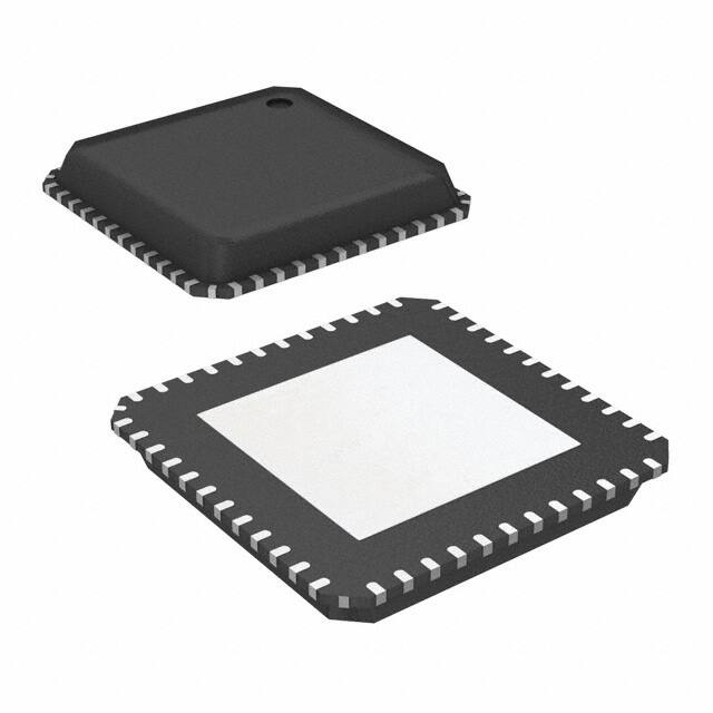


 工商网监
湘ICP备2023018690号
工商网监
湘ICP备2023018690号
