Product Specification
Quadwire 40 Gb/s Parallel Active Optical Cable
FCCx410QD3Cyy
®
PRODUCT FEATURES
•
Four-channel full-duplex active
optical cable
•
Multirate capability: 1.06Gb/s to
10.5Gb/s per channel
•
Complies with QSFP MSA highdensity form factor
•
Round, plenum-rated (OFNP) and
riser-rated (OFNR), low smoke
zero halogen (LSZH) cables
•
Connectivity Diagnostics® ready
•
Rigid pull-tab with embedded LED
light
•
Hot Pluggable
•
Low power dissipation: 60 mm on the rest of the cable.
2. Non-condensing.
V.
Electrical Characteristics (TOP = 0 to 70°°C, VCC = 3.3 ± 5% Volts)
Parameter
Supply Voltage
Supply Current
Link Turn-On Time
Transmit Turn-On Time
Transmitter (per Lane)
Differential data input swing
Differential input threshold
Receiver (per Lane)
Differential data output swing
Power Supply Ripple Tolerance
Symbol
Vcc1,
VccTx,
VccRx
Icc
Vin,pp
Min
3.15
Typ
180
Max
3.45
Unit
V
350
mA
2000
ms
1
1200
mVpp
mV
2
800
mVpp
mVpp
3,4
50
Vout,pp
PSR
Finisar Corporation – 16-Janunary-2016
0
50
Rev. A1
Ref.
Page 4
�FCCx410QD3Cxx Product Specification – July 2016
Notes:
1. From power-on and end of any fault conditions.
2. AC coupled internally. See Figure 2 for input eye mask requirements. Self-biasing 100Ω differential
input.
3. AC coupled with 100Ω differential output impedance. See Figure 3 for output eye mask.
4. Settable in 4 discrete steps. See Figure 5 for Vo settings
VI.
High-Speed Electrical Characteristics per Lane
(TOP = 0 to 70°°C, VCC = 3.3 ± 5% Volts)
Parameter –Inputs
Reference Differential Input
Impedance
Termination Mismatch
Symbol
Conditions
Min
Zd
Typ
Max
Units
Ω
Ref.
5
%
mV
(RMS)
dB
dB
1
100
∆ZM
Input AC Common Mode Voltage
Differential Input Return Loss
Differential to Common Mode
Loss
Jitter Tolerance (Total)
Jitter Tolerance (Deterministic)
25
SDD11
0.01-4.1 GHz
4.1 – 11.1 GHz
SCD11
0.01-11.1 GHz
TJ
DJ
-10
dB
0.40
0.15
UI
UI
2
3
Notes:
1. See SFF-8431 Rev 3.2 (SFP+) section D.15 Termination Mismatch for definition & test recommendations
2. Reflection coefficient given by equation SDD11(dB)< -12+2*SQRT(f), with f in GHz. See Figure 4.
3. Reflection coefficient given by equation SDD11(dB)< -6.3+13Log10(f/5.5), with f in GHz. See Figure 4.
500
400
Vdiff (mV)
300
200
100
0
-100
-200
-300
-400
-500
0
0.2
0.4
0.6
0.8
1
UI
Figure 2 – Transmitter Input Differential Signal Mask
Finisar Corporation – 16-Janunary-2016
Rev. A1
Page 5
�FCCx410QD3Cxx Product Specification – July 2016
Parameter –Outputs
Reference Differential Output Impedance
Termination Mismatch
Output AC Common Mode Voltage
Output Rise and Fall time (20% to 80%)
Symbol
Conditions
Min
Zd
∆ZM
Typ
Max
100
5
15
tRH, tFH
Differential Output Return Loss
SDD22
Common Mode Output Return Loss
SCC22
24
0.01-4.1 GHz
4.1 – 11.1 GHz
0.01-2.5 GHz
2.5-11.1 GHz
-3
Units
Ref.
Ω
%
mVRMS
ps
dB
dB
dB
dB
Notes:
1. Reflection coefficient given by equation SDD22(dB)< -12+2*SQRT(f), with f in GHz. See Figure 4.
2. Reflection coefficient given by equation SDD22(dB)< -6.3+13Log10(f/5.5), with f in GHz. See Figure 4.
3. Reflection coefficient given by equation SCC22(dB)< -7+1.6*f, with f in GHz.
Receiver Output Jitter Specification
Deterministic Jitter
Total Jitter
Symbol
DJOUT
TJOUT
Min
Typ
Max
0.38
0.64
Units
UI
UI
Ref.
1
1
Notes:
1. When transmitter input jitter specs are met.
Other Informational Specifications
(not tested)
Max Bit Rate NRZ
Low Frequency 3dB Cutoff
Ch / Ch crosstalk
Output Pre-emphasis settings
(user selectable)
Pre-Emphasis pulse width
Channel-to-channel skew
Latency
Digital clock to data delay
Digital output rise/fall times
Digital input / output Cap
Digital input logic High
Digital input logic Low
ESD Signal pads
ESD (other pads)
Symbol
Min
B
fc
175
Typ
Max
Units
10.5
Gb/s
kHz
dB
mV
mV
mV
mV
ps
ns
ns
ns
ns
pF
V
V
V
kV
-26
0
125
175
325
PE
60
400
495
90
24
600
25
5
1
2
1
500
2
Ref.
1
1
2
2
Notes:
1. For worst-case 100m length.
2. Human Body Model (HBM)
Finisar Corporation – 16-Janunary-2016
Rev. A1
Page 6
1
2
3
�FCCx410QD3Cxx Product Specification – July 2016
500
400
300
Vdiff (mV)
200
100
0
-100
-200
-300
-400
-500
0
0.2
0.4
0.6
0.8
1
UI
Figure 3 – Receiver Output Differential Signal Mask
0
-2
-4
-6
dB
-8
-10
-12
-14
-16
-18
-20
0
1
2
3
4
5
6
7
8
9
10
11
12
GHz
Figure 4 – Maximum Transmitter Input and Receiver Output Differential Return Loss
Finisar Corporation – 16-Janunary-2016
Rev. A1
Page 7
�FCCx410QD3Cxx Product Specification – July 2016
Vo (mV)
Power (mW)
0
317
422
739
Pre-Emphasis into 100ohms (mV)
0
125
175
325
599
751
935
971
1075
787
971
1007
1111
883
1055
1103
1190
Figure 5 – Power Dissipation (mW, maximum) vs. Rx Output Conditions
VII.
Memory Map and Control Registers
Compatible with SFF-8436.2 Please see Finisar Application Note AN-2075: Quadwire®
EEPROM Mapping3 for details.
VIII. Environmental Specifications
Finisar Quadwire® active optical cables have an operating temperature range from 0°C to
+70°C case temperature.
Environmental Specifications
Case Operating Temperature
Storage Temperature
1.
IX.
Symbol
Min
Top
Tsto
0
-40
Typ
Max
Units
Ref.
70
85
°C
°C
1
Assumes no mechanical load force on the unit. Ensuring no mechanical load force requires a cable bend
radius of >105 mm within 100 mm of either cable end module and >60 mm on the rest of the cable.
Regulatory Compliance
Finisar Quadwire® active optical cables are RoHS-6 Compliant. Copies of certificates are
available at Finisar Corporation upon request.
Quadwire® active optical cables are Class 1 laser eye safety compliant per IEC 60825-1.
The round cable jacket is available in both plenum-rated (OFNP) and riser-rated (OFNR)
low smoke zero-halogen (LSZH).
Finisar Corporation – 16-Janunary-2016
Rev. A1
Page 8
�FCCx410QD3Cxx Product Specification – July 2016
X.
Mechanical Specifications
The Quadwire® mechanical specifications are based on QSFP transceiver module
specifications, substituting the MPO connectors with a cable connecting both ends. Rigid
pull-tab is opaque in non-illuminated mode and amber in illuminated mode.
Figure 5 – Quadwire® with Connectivity Diagnostics® mechanical drawing
Cable Mechanical Specifications
Min
Minimum bend radius
Minimum bend radius within 100
mm of the Quadwire® module end
Diameter
60
mm
105
mm
Insertion, Extraction and Retention
Forces
Cable Proof (Tensile) Test (0º)
Cable Proof (Tensile) Test (90º)
Impact Test
Flex Test
Twist Test
Module retention
Host Connector Retention
Finisar Corporation – 16-Janunary-2016
3.0
Typical
3.3
Max
3.6
Min
Max
Units
90
180
44.0
33.0
8
8.9
13.0
N/A
N/A
Newtons
Newtons
Cycles
Newtons
Newtons
Newtons
Newtons
Rev. A1
Units
mm
Notes
1.5m drop
No damage below 90N
No damage below 180N
Page 9
�FCCx410QD3Cxx Product Specification – July 2016
Figure 6 – Quadwire® production-level product label
XI.
References
1.
INF-8438i – Specification for QSFP (Quad Small Formfactor Pluggable)
Transceiver, Rev 1.0, November 2006
2.
SFF-8636 – Specification for QSFP+ Copper and Optical Transceiver, Rev 2.7,
January 2016
3.
Application Note AN-2075: Quadwire® EEPROM Mapping, Rev E
4.
Application Note AN-2158: Finisar’s Connectivity Diagnostics™ for Active Optical
Cables
XII.
For More Information
Finisar Corporation
1389 Moffett Park Drive
Sunnyvale, CA 94089-1133
Tel. 1-408-548-1000
Fax 1-408-541-6138
sales@finisar.com
www.finisar.com
Finisar Corporation – 16-Janunary-2016
Rev. A1
Page 10
�
很抱歉,暂时无法提供与“FCCN410QD3C05”相匹配的价格&库存,您可以联系我们找货
免费人工找货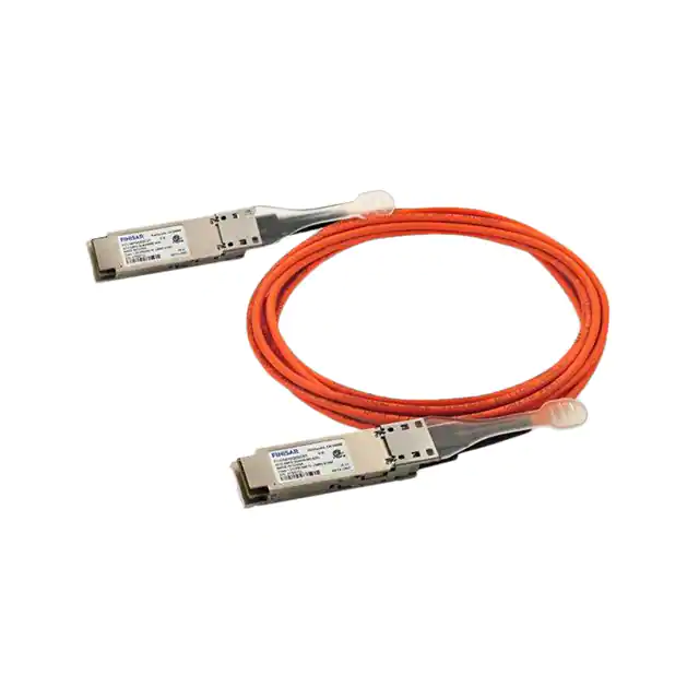


 工商网监
湘ICP备2023018690号
工商网监
湘ICP备2023018690号
