TTL-232RG-VREG3V3-WE 数据手册
TTL to USB Serial Converter Generic Cables Datasheet
Version 1.5
Document Reference No.: FT_000188
Clearance No.: FTDI# 129
Future Technology Devices International Ltd
TTL-232RG
TTL to USB Serial Converter Generic
Cables
Datasheet
Version 1.5
Issue Date: 2018-05-04
Neither the whole nor any part of the information contained in, or the product described in this manual, may be adapted or reproduced
in any material or electronic form without the prior written consent of the copyright holder. This product and its documentation are
supplied on an as-is basis and no warranty as to their suitability for any particular purpose is either made or implied. Future Technology
Devices International Ltd will not accept any claim for damages howsoever arising as a result of use or fa ilure of this product. Your
statutory rights are not affected. This product or any variant of it is not intended for use in any medical appliance, device or system in
which the failure of the product might reasonably be expected to result in personal injury. This document provides preliminary
information that may be subject to change without notice. No freedom to use patents or other intellectual property rights is implied by
the publication of this document. Future Technology Devices International Ltd, Unit 1, 2 Seaward Place, Centurion Business Park,
Glasgow, G41 1HH, United Kingdom. Scotland Registered Number: SC136640
Copyright © Future Technology Devices International Limited
1
�TTL to USB Serial Converter Generic Cables Datasheet
Version 1.5
Document Reference No.: FT_000188
Clearance No.: FTDI# 129
1 Introduction
The TTL-232RG generic cables are a family of USB to TTL serial UART converter cables incorporating
FTDI’s FT232RQ USB to Serial UART interface IC device which handles all the USB signalling and
protocols. The cables provide a fast, simple way to connect devices with a logic level serial interface to
USB.
Each TTL-232RG generic cable contains a small internal electronic circuit board, utilising the FT232R,
which is encapsulated into the USB connector end of the cable. The FT232R datasheet is available at
http://www.ftdichip.com/Support/Documents/DataSheets.htm. The other end of the cable is wire ended.
The cables can be used for “TTL” or interface logic over a range to voltage levels.
Cables are FCC, CE, and RoHS compliant at TTL levels of + 5V to + 1.8V.
The USB side of the cable is USB powered and is USB 2.0 full speed compatible. Each cable is 1.8m long
and supports a data transfer rate up to 3 Mbaud. Each cable supports the FTDIChip-ID™, with a unique
USB serial number programmed into the FT232R. This feature can be used to create a security or
password protected file transfer access using the cable. Further information and examples on this feature
are available at http://www.ftdichip.com under FTDIChip-ID Projects.
The TTL-232RG generic cables require USB drivers, available free from http://www.ftdichip.com, which
are used to make the FT232R in the cable appear as a virtual COM port (VCP). This then allows the user
to communicate with the USB interface via a standard PC serial emulation port (for example TTY).
Another FTDI USB driver, the D2XX driver, can also be used with application software to directly access
the FT232R on the cable though a DLL. This is illustrated in the Figure 1.1
Figure 1.1 - Using the TTL-232RG Generic Cable
Copyright © Future Technology Devices International Limited
2
�TTL to USB Serial Converter Generic Cables Datasheet
Version 1.5
Document Reference No.: FT_000188
Clearance No.: FTDI# 129
1.1 Available Cables and Part Numbers
The following Table 1.1 gives details of the available TTL-232RG generic cables.
Part Number
Description
End
Connector*
Cable details
USB to UART cable with +3.3V
TTL-232RG-
TTL level UART signals. Maximum
Wire Ended (no
6 core, UL2464 24 AWG,
VSW3V3-WE
output of 50mA on VCC
connector)
diam=5mm
(see Note 1 and Note 4)
USB to UART cable with +3.3V
TTL-232RG-
TTL level UART signals. Maximum
Wire Ended (no
6 core, UL2464 24 AWG,
VREG3V3-WE
output of 250mA on VCC
connector)
diam=5mm
(see Note 2 and 5)
USB to UART cable with +1.8V
TTL-232RG-
TTL level UART signals. Maximum
Wire Ended (no
6 core, UL2464 24 AWG,
VREG1V8-WE
output of 100mA on VCC
connector)
diam=5mm
(see Note 2 and 6)
USB to UART cable with up to 5V
TTL-232RG-
TTL level UART signals. Maximum
Wire Ended (no
6 core, UL2464 24 AWG,
VSW5V-WE
output of 450mA on VCC
connector)
diam=5mm
Wire Ended (no
6 core, UL2464 24 AWG,
connector)
diam=5mm
(see Note 7)
USB to UART cable with TTL
Voltage levels for the UART
TTL-232RGVIP-WE
signals are supplied from the
customers interface logic
(see Note 3 and 8)
Table 1.1 TTL-232RG Generic Cables Descriptions and Part Numbers
Note 1: Fixed 3.3V signals and supply.
Note 2: Any regulator from 1.8V to 5V can be used. 1.8V and 3.3V versions are standard products.
Others values are customized at the factory.
Note 3: Any INPUT voltage can be supplied by the customer from 1.8V (min value of VCCIO) to +5.25V
(Max value of VCCIO)
Note 4: The VCC power output signal (RED wire) is 3.3V. The source of 3.3V is the FT232R regulator
output, which is switched onto the power output signal.
Note 5: The VCC power output signal (RED wire) is 3.3V. The source of 3.3V is on board 3.3V regulator
output, which is switched onto the power output signal
Note 6: The VCC power output signal (RED wire) is 1.8V. The source of 1.8V is on board 1.8V regulator
output, which is switched onto the power output signal
Copyright © Future Technology Devices International Limited
3
�TTL to USB Serial Converter Generic Cables Datasheet
Version 1.5
Document Reference No.: FT_000188
Clearance No.: FTDI# 129
Note 7: The VCC power output signal (RED wire) is 5.0V. The source of 5.0V is the USB VBUS input,
which is switched onto the power output signal. At the time of releasing these cables, this cable was not
available. It will become available at a later date. Please contact FTDI Sales for further information.
Note 8: The VCC power input signal (RED wire) is an output from customer electronics, an input to the
cable. This value=i/pV. The source of i/pV is from customer’s interface logic and this is used to drive the
VCCIO and hence the signal levels on the wires. This makes the generic cable customisable to whatever
output voltage the customer interface is operating at 1.8V to 5.25V range.
FTDI supports customised end connector designs. For more information, please contact your local FTDI sales office
(see end of datasheet for contact details).
1.2 Certifications
The FTDI TTL-232RG range of generic cables is fully RoHS compliant and FCC/CE approved.
Copyright © Future Technology Devices International Limited
4
�TTL to USB Serial Converter Generic Cables Datasheet
Version 1.5
Document Reference No.: FT_000188
Clearance No.: FTDI# 129
Table of Contents
1
2
Introduction .................................................................... 2
1.1
Available Cables and Part Numbers........................................... 3
1.2
Certifications ............................................................................ 4
Typical Applications ........................................................ 6
2.1
Driver Support .......................................................................... 6
2.2
Features .................................................................................... 7
3
FT232R features applicable to TTL-232RG generic cables 8
4
TTL-232RG generic cable connection/mechanical details 9
4.1
TTL-232RG Generic Cables Signal Descriptions ......................... 9
4.2
TTL-232RG Generic Cables Electrical Parameters .................... 10
4.2.1
TTL-232RG-VSW3V3-WE Electrical Parameters ............................................ 10
4.2.2
TTL-232RG-VREG3V3-WE Electrical Parameters........................................... 10
4.2.3
TTL-232RG-VREG1V8-WE Electrical Parameters........................................... 11
4.2.4
TTL-232RG-VSW5V-WE Electrical Parameters ............................................. 11
4.2.5
TTL-232RG-VIP-WE Electrical Parameters ................................................... 12
5
Cable PCB Circuit Schematic .......................................... 13
6
Contact Information ...................................................... 14
Appendix A - Cable EEPROM Configuration......................... 16
Appendix B - References .................................................... 18
Document References ..................................................................... 18
Acronyms and Abbreviations ........................................................... 18
Appendix C - List of Figures and Tables ............................. 19
List of Figures ................................................................................. 19
List of Tables ................................................................................... 19
Appendix C – Revision History ........................................... 20
Copyright © Future Technology Devices International Limited
5
�TTL to USB Serial Converter Generic Cables Datasheet
Version 1.5
Document Reference No.: FT_000188
Clearance No.: FTDI# 129
2 Typical Applications
USB to Serial TTL Level Converter
Upgrading Legacy Peripherals to USB
Interface Microcontroller UART or I/O to USB
Interface FPGA / PLD to USB
Interface to FTDI VDRIVE2 or VMUSIC2
modules.
Interface USB to none-standard (application
dependant) logic levels.
Replace MAX232 type level shifters allowing for
direct connection of products to PC via USB
USB Instrumentation PC interface
USB Industrial Control
USB Software / Hardware Encryption Dongles
2.1 Driver Support
Royalty free VIRTUAL COM PORT
Royalty free D2XX Direct Drivers
(VCP) DRIVERS for...
(USB Drivers + DLL S/W Interface)
Windows 10 32,64-bit
Windows 10 32,64-bit
Windows 8/8.1 32,64-bit
Windows 8/8.1 32,64-bit
Windows 7 32,64-bit
Windows 7 32,64-bit
Windows Vista and Vista 64-bit
Windows Vista and Vista 64-bit
Windows XP and XP 64-bit
Windows XP and XP 64-bit
Windows 98, 98SE, ME, 2000, Server 2003, XP,
Server 2008 and server 2012 R2
Windows 98, 98SE, ME, 2000, Server 2003, XP,
Server 2008 and server 2012 R2
Windows XP Embedded
Windows XP Embedded
Windows CE 4.2, 5.0 and 6.0
Windows CE 4.2, 5.0 and 6.0
Mac OS 8/9, OS-X
Linux 2.4 and greater
Linux 2.4 and greater
Android (J2xx)
The drivers listed above are all available to download for free from http://www.ftdichip.com. Various 3rd
Party Drivers are also available for various other operating systems - see http://www.ftdichip.com for
details.
Copyright © Future Technology Devices International Limited
6
�TTL to USB Serial Converter Generic Cables Datasheet
Version 1.5
Document Reference No.: FT_000188
Clearance No.: FTDI# 129
2.2 Features
TTL-232RG generic converter cable provides a
USB to TTL Serial interface with various logic
levels.
On board FT232RQ provides single chip USB to
asynchronous serial data transfer interface.
Entire USB protocol handled by the electronics
in the cable USB.
Support for FT232R FTDIChip-ID™ feature for
improved security.
Voltage output power allows external logic to
be powered from the USB port.
Cable can be used to accept IO voltage from
application interface logic allowing users to
supply IO voltage levels.
Connect directly to a microcontroller UART or
I/O pins.
6 way outputs provide Tx, Rx, RTS#, CTS#,
VCC and GND.
UART interface support for 7 or 8 data bits, 1
or 2 stop bits and odd / even / mark / space /
no parity.
Low USB bandwidth consumption.
UHCI / OHCI / EHCI host controller compatible.
USB 2.0 (12Mb/s) Full Speed compatible.
-40°C to +85°C operating temperature range.
Cable length is 1.80m (6 feet).
FCC and CE compliant.
Custom versions also available (subject to
MOQ).
Fully assisted hardware (RTS#/CTS#) or X-On
/ X-Off software handshaking.
Data transfer rates from 300 baud to 3 Mbaud
at TTL levels.
Internal EEPROM with user writeable area.
Wide range of output drive voltages 1.8V to
5.0V safe TTL inputs makes the TTL-232RG
easy to interface to 5.0V MCU’s.
FTDI’s
royalty-free
VCP
allow
for
communication as a standard emulated COM
port and D2XX ‘direct’ drivers provide DLL
application programming interface.
Copyright © Future Technology Devices International Limited
7
�TTL to USB Serial Converter Generic Cables Datasheet
Version 1.5
Document Reference No.: FT_000188
Clearance No.: FTDI# 129
3 FT232R features applicable to TTL-232RG generic cables
The TTL-232RG generic cables use FTDI’s FT232RQ USB to serial IC device. This section summarises the
key features of the FT232RQ which apply to the TTL-232RG USB to serial TTL converter cables. For
further details, and a full features and enhancements description consult the FT232R datasheet, this is
available from http://www.ftdichip.com.
Internal EEPROM. The internal EEPROM in each cable is used to store USB Vendor ID (VID), Product ID
(PID), device serial number, product description string and various other USB configuration descriptors.
Each cable is supplied with the internal EEPROM pre-programmed as described in Appendix AError!
Reference source not found.. A user area of the internal EEPROM is available to system designers to
allow storing additional data. The internal EEPROM descriptors can be programmed in circuit, over USB
without any additional voltage requirement. It can be programmed using the FTDI utility software called
MPROG, which can be downloaded from FTDI Utilities on the FTDI website (www.ftdichip.com).
Lower Operating and Suspend Current. The FT232R has a low 15mA operating supply current and a
very low USB suspend current of approximately 70μA. (Note that during suspend mode, the current
drawn by application should not exceed 2.5mA to remain USB compliant)
Low USB Bandwidth Consumption. The USB interface of the FT232R, and therefore the TTL-232RG
cables has been designed to use as little as possible of the total USB bandwidth available from the USB
host controller.
High Output Drive Option. The UART interface I/O pins on the TTL-232RG cables (RXD, TXD, RTS#,
and CTS#) can be configured to use the FT232R’s high output drive option. This option allows the FT232R
I/O pins to drive up to three times the standard signal drive level. This allows multiple devices to be
driven, or devices that require greater signal drive strength to be interfaced to the cables. This option is
enabled in the internal EEPROM.
UART Pin Signal Inversion. The sense of each of the eight UART signals can be individually inverted by
configuring options in the internal EEPROM. For example CTS# (active low) can be changed to CTS
(active high), or TXD can be changed to TXD#.
FTDIChip-ID™. The FT232R includes the FTDIChip-ID™ security dongle feature. This FTDIChip-ID™
feature allows a unique number to be burnt into each cable during manufacture. This number cannot be
reprogrammed. This number is only readable over USB can be used to form the basis of a security dongle
which can be used to protect any customer application software being copied. This allows the possibility
of using the TTL-232RG cables as a dongle for software licensing. Further to this, a renewable license
scheme can be implemented based on the FTDIChip-ID™ number when encrypted with other information.
This encrypted number can be stored in the user area of the FT232R internal EEPROM, and can be
decrypted, then compared with the protected FTDIChip-ID™ to verify that a license is valid. Web based
applications can be used to maintain product licensing this way. An application note, AN232R-02,
available from FTDI website (www.ftdichip.com) describes this feature.
Improved EMI Performance. The TTL-232RG cables are FCC and CE certified.
Extended Operating Temperature Range - The TTL-232RG generic cables are capable of operating
over an extended temperature range of -40º to +85º C thus allowing them to be used in automotive or
industrial applications.
Copyright © Future Technology Devices International Limited
8
�TTL to USB Serial Converter Generic Cables Datasheet
Version 1.5
Document Reference No.: FT_000188
Clearance No.: FTDI# 129
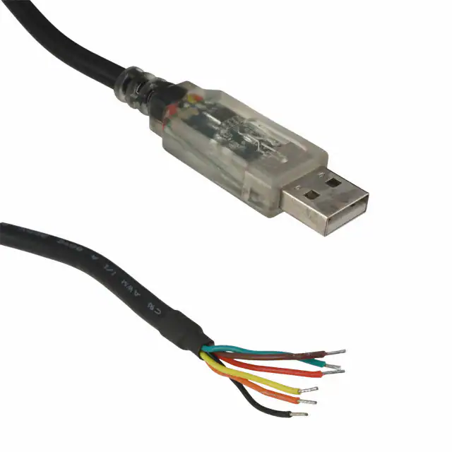
4 TTL-232RG generic cable connection/mechanical details
The following Figure 4.1 shows the cable signals and the wire colours for these signals on the TTL-232RG
generic cables.
Figure 4.1 TTL-232RG Generic Cables Connections (numbers refer to pad numbers on the PCB)
Figure 4.2 TTL-232RG Generic Cables Mechanical Details (dimensions in mm)
4.1 TTL-232RG Generic Cables Signal Descriptions
Colour
Name
Type
Description
Black
GND
GND
Device ground supply pin.
Brown
CTS#
Input
Clear to Send Control input / Handshake signal.
Red
VCC
Output
or input
Orange
TXD
Output
Yellow
RXD
Input
Green
RTS#
Output
Power Supply Output except for the TTL-232RG-VIPWE were this is an input and power is supplied by
the application interface logic.
Transmit Asynchronous Data output.
Receive Asynchronous Data input.
Request To Send Control Output / Handshake signal.
Table 4.1 TTL-232RG Generic Cables Signal Descriptions
Copyright © Future Technology Devices International Limited
9
�TTL to USB Serial Converter Generic Cables Datasheet
Version 1.5
Document Reference No.: FT_000188
Clearance No.: FTDI# 129
4.2 TTL-232RG Generic Cables Electrical Parameters
4.2.1 TTL-232RG-VSW3V3-WE Electrical Parameters
Parameter
VCC
IO
T
Description
Minimum
Typical
Maximum
Units
3.2
3.3
3.4
V
-
50
-
mA
+85
oC
Output Power
Voltage
Output Power
Current
Operating
-40
Temperature Range
Conditions
Must be less than 2.5mA
during suspend.
Table 4.2 TTL-232RG-VSW3V3-WE I/O Operating Parameters
Parameter
Description
Minimum
Typical
Maximum
Units
Conditions
Voh
Output Voltage High
2.2
2.8
3.2
V
I source = 1mA
Vol
Output Voltage Low
0.3
0.4
0.6
V
I sink = 2mA
Vin
Input Switching Threshold
1.0
1.2
1.5
V
VHys
Input Switching Hysteresis
20
25
30
mV
Table 4.3 TTL-232RG-VSW3V3-WE I/O Pin Characteristics
4.2.2 TTL-232RG-VREG3V3-WE Electrical Parameters
Parameter
VCC
IO
T
Description
Minimum
Typical
Maximum
Units
3.2
3.3
3.4
V
Output Power
Voltage
Output Power
250
Current
Operating
Temperature Range
Conditions
Must be less than 2.5mA
mA
-40
+85
during suspend.
oC
Table 4.4 TTL-232RG-VREG3V3-WE I/O Operating Parameters
Parameter
Description
Minimum
Typical
Maximum
Units
Conditions
Voh
Output Voltage High
2.2
2.8
3.2
V
I source = 3mA
Vol
Output Voltage Low
0.3
0.4
0.6
V
I sink = 8mA
Vin
Input Switching Threshold
1.0
1.2
1.5
V
VHys
Input Switching Hysteresis
20
25
30
mV
Table 4.5 TTL-232RG-VREG3V3 Pin Characteristics
Copyright © Future Technology Devices International Limited
10
�TTL to USB Serial Converter Generic Cables Datasheet
Version 1.5
Document Reference No.: FT_000188
Clearance No.: FTDI# 129
4.2.3 TTL-232RG-VREG1V8-WE Electrical Parameters
Parameter
VCC
IO
T
Description
Minimum
Typical
Maximum
Units
1.32
1.62
1.8
V
Output Power
Voltage
Output Power
100
Current
Operating
100mA for output
mA
-40
Temperature Range
Conditions
+85
powerless than 3.0V
oC
Table 4.6 TTL-232RG-VREG1V8 I/O Operating Parameters
Parameter
Description
Minimum
Typical
Maximum
Units
Conditions
Voh
Output Voltage High
1.32
1.62
1.8
V
I source = 6mA
Vol
Output Voltage Low
0.06
0.1
0.18
V
I sink = 6mA
Vin
Input Switching Threshold
1.0
1.2
1.5
V
VHys
Input Switching Hysteresis
20
25
30
mV
Table 4.7 TTL-232RG-VREG1V8-WE I/O Pin Characteristics
4.2.4 TTL-232RG-VSW5V-WE Electrical Parameters
Parameter
VCC
IO
T
Description
Output Power
Voltage
Minimum
Typical
Maximum
Units
4.25
5.0
5.25
V
-
450
Supply Current
Operating
Temperature Range
mA
-40
+85
Conditions
Must be less than 2.5mA
during suspend.
oC
Table 4.8 TTL-232RG-VSW5V-WE I/O Operating Parameters
Parameter
Description
Minimum
Typical
Maximum
Units
Conditions
Voh
Output Voltage High
3.2
4.1
4.9
V
I source = 6mA
Vol
Output Voltage Low
0.3
0.4
0.6
V
I sink = 6mA
Vin
Input Switching Threshold
1.0
1.2
1.5
V
VHys
Input Switching Hysteresis
20
25
30
mV
Table 4.9 TTL-232RG-VSW5V-WE I/O Pin Characteristics
Copyright © Future Technology Devices International Limited
11
�TTL to USB Serial Converter Generic Cables Datasheet
Version 1.5
Document Reference No.: FT_000188
Clearance No.: FTDI# 129
4.2.5 TTL-232RG-VIP-WE Electrical Parameters
Parameter
VCC
IO
T
Description
Minimum
Power Input for I/O
Supply Current
Temperature Range
Maximum
Units
5.25
V
*
mA
+85
oC
INPUT
1.8
Buffer
Operating
Typical
i/p
*
*
-40
Conditions
Must be less than
2.5mA during suspend.
Table 4.10 TTL-232RG-VIP-WE I/O Operating Parameters
Parameter
Description
Minimum
Typical
Maximum
Units
Conditions
Voh
Output Voltage High
*
*
*
V
I source = 6mA
Vol
Output Voltage Low
*
*
*
V
I sink = 6mA
Vin
Input Switching Threshold
*
*
*
V
VHys
Input Switching Hysteresis
*
*
*
mV
Table 4.11 TTL-232RG-VIP-WE I/O Pin Characteristics
*depends on supplied voltage
Copyright © Future Technology Devices International Limited
12
�TTL to USB Serial Converter Generic Cables Datasheet
Version 1.5
Document Reference No.: FT_000188
Clearance No.: FTDI# 129
5 Cable PCB Circuit Schematic
The circuit schematic for the small internal electronic circuit board, utilising the FTDI FT232R, which is
encapsulated into the USB connector end of the cable, is shown in
Figure 5.1.
Customised versions of these cables are also available. Users interested in customised versions of these
cables should contact FTDI sales (sales1@ftdichip.com).
Figure 5.1 Circuit Schematic of PCB Used in the generic TTL to USB Serial Converter Cables
Copyright © Future Technology Devices International Limited
13
�TTL to USB Serial Converter Generic Cables Datasheet
Version 1.5
Document Reference No.: FT_000188
Clearance No.: FTDI# 129
6 Contact Information
Head Office – Glasgow, UK
Branch Office – Tigard, Oregon, USA
Future Technology Devices International Limited
Unit 1, 2 Seaward Place,
Centurion Business Park
Glasgow, G41 1HH
United Kingdom
Tel: +44 (0) 141 429 2777
Fax: +44 (0) 141 429 2758
Future Technology Devices International Limited (USA)
7130 SW Fir Loop
Tigard, OR 97223-8160
USA
Tel: +1 (503) 547 0988
Fax: +1 (503) 547 0987
E-mail (Sales)
E-mail (Support)
E-mail (General Enquiries)
Web Shop URL
sales1@ftdichip.com
support1@ftdichip.com
admin1@ftdichip.com
http://www.ftdichip.com
E-Mail (Sales)
E-mail (Support)
E-mail (General Enquiries)
us.sales@ftdichip.com
us.support@ftdichip.com
us.admin@ftdichip.com
Branch Office – ShangHai, China
Branch Office – Taipei, Taiwan
Future Technology Devices International Limited
(Taiwan)
2F, No. 516, Sec. 1, NeiHu Road
Taipei 114
Taiwan, R.O.C.
Tel: +886 (0) 2 8797 1330
Fax: +886 (0) 2 8751 9737
E-mail (Sales)
E-mail (Support)
E-mail (General Enquiries)
tw.sales1@ftdichip.com
tw.support1@ftdichip.com
tw.admin1@ftdichip.com
Future Technology Devices International Limited
(China)
Room 1103, No. 666 West Huaihai Road,
Shanghai, 200052
China
Tel: +86 (21) 62351596
Fax: +86 (21) 62351595
E-Mail (Sales)
cn.sales@ftdichip.com
E-mail (Support)
cn.support@ftdichip.com
E-Mail (General Enquiries) cn.admin@ftdichip.com
Web Site URL: http://www.ftdichip.com
Distributor and Sales Representatives
Please visit the Sales Network page of the FTDI Web site for the contact details of our distributor(s) and
sales representative(s) in your country.
System and equipment manufacturers and designers are responsible to ensure that their systems, and any Future Technology Devices
International Ltd (FTDI) devices incorporated in their systems, meet all applicable safety, regulatory and system-level performance
requirements. All application-related information in this document (including application descriptions, suggested FTDI devices and other
materials) is provided for reference only. While FTDI has taken care to assure it is accurate, this information is subject to customer
confirmation, and FTDI disclaims all liability for system designs and for any applications assistance provided by FTDI. Use of FTDI
devices in life support and/or safety applications is entirely at the user’s risk, and the user agrees to defend, indemnify a nd hold
harmless FTDI from any and all damages, claims, suits or expense resulting from such use. This document is subject to change without
notice. No freedom to use patents or other intellectual property rights is implied by the publication of this document. Neith er the whole
nor any part of the information contained in, or the product described in this document, may be adapted or reproduced in any material
or electronic form without the prior written consent of the copyright holder. Future Technology Devices International Ltd, Un it 1, 2
Seaward Place, Centurion Business Park, Glasgow G41 1HH, United Kingdom. Scotland Registered Company Number: SC136640
Copyright © Future Technology Devices International Limited
14
�TTL to USB Serial Converter Generic Cables Datasheet
Version 1.5
Document Reference No.: FT_000188
Clearance No.: FTDI# 129
Appendix A - Cable EEPROM Configuration
Each TTL-232RG cable is controlled by the FTDI FT232R IC. This FT232R device contains an EEPROM
which contains the USB configuration descriptors for that device. When the cable is plugged into a PC or a
USB reset is performed, the PC will read these descriptors. The default values stored into the internal
EEPROM are defined in the following table.
Parameter
Value
USB Vendor ID (VID)
0403h
FTDI default VID (hex)
USB Product UD (PID)
6001h
FTDI default PID (hex)
Serial Number
Enabled?
Notes
Yes
A unique serial number is generated and programmed into the
Serial Number
Pull down I/O Pins in
USB Suspend
Manufacturer Name
See Note
EEPROM during device final test.
Enabling this option will make the device pull down on the UART
Disabled
interface lines when the power is shut off (PWREN# is high).
FTDI
Product description depends on the cable. The following lists a few
of the Product description for each different cable.
TTL-232RG-VSW3V3
Product Description
See note
TTL-232RG-VREG3V3
TTL-232RG-VREG1V8
TTL-232RG-VREGxVx
TTL-232RG-VIP
Max Bus Power Current
Power Source
90mA
Bus
Powered
Device Type
FT232R
USB Version
0200
Returns USB 2.0 device description to the host.
Note: The device is a USB 2.0 Full Speed device (12Mb/s).
Remote Wake Up
Disabled
500uA suspend limit when in this state
High Current I/Os
Enabled
Enables the high drive level on the UART and CBUS I/O pins.
Load VCP Driver
Enabled
Makes the device load the VCP driver interface for the device.
Invert TXD
Disabled
Signal on this pin becomes TXD# if enable.
Invert RXD
Disabled
Signal on this pin becomes RXD# if enable.
Copyright © Future Technology Devices International Limited
16
�TTL to USB Serial Converter Generic Cables Datasheet
Version 1.5
Document Reference No.: FT_000188
Parameter
Value
Invert RTS#
Disabled
Signal on this pin becomes RTS if enable.
Invert CTS#
Disabled
Signal on this pin becomes CTS if enable.
Clearance No.: FTDI# 129
Notes
Copyright © Future Technology Devices International Limited
17
�TTL to USB Serial Converter Generic Cables Datasheet
Version 1.5
Document Reference No.: FT_000188
Clearance No.: FTDI# 129
Appendix B - References
Document References
NA
Acronyms and Abbreviations
Terms
DLL
EEPROM
Description
Dynamic Link Library
Electrically Erasable Programmable Read Only Memory
EHCI
Enhanced Host Controller Interface
FCC
Federal Communications Commission
FPGA
I/O
OHCI
PC
Field Programmable Gate Array
Input Output
Open Host Controller Interface
Personal Computer
PLD
Programmable Logic Device
TTL
Transistor-Transistor Logic
UART
Universal Asynchronous Receiver Transmitter
UHCI
Universal Host Controller Interface
USB
Universal Serial Bus
VCP
Virtual COM Port
Copyright © Future Technology Devices International Limited
18
�TTL to USB Serial Converter Generic Cables Datasheet
Version 1.5
Document Reference No.: FT_000188
Clearance No.: FTDI# 129
Appendix C - List of Figures and Tables
List of Figures
Figure 1.1 - Using the TTL-232RG Generic Cable .............................................................................. 2
Figure 4.1 TTL-232RG Generic Cables Connections (numbers refer to pad numbers on the PCB) ............. 9
Figure 4.2 TTL-232RG Generic Cables Mechanical Details (dimensions in mm) ...................................... 9
Figure 5.1 Circuit Schematic of PCB Used in the generic TTL to USB Serial Converter Cables ................ 13
List of Tables
Table 1.1 TTL-232RG Generic Cables Descriptions and Part Numbers .................................................. 3
Table 4.1 TTL-232RG Generic Cables Signal Descriptions ................................................................... 9
Table 4.2 TTL-232RG-VSW3V3-WE I/O Operating Parameters .......................................................... 10
Table 4.3 TTL-232RG-VSW3V3-WE I/O Pin Characteristics ............................................................... 10
Table 4.4 TTL-232RG-VREG3V3-WE I/O Operating Parameters ......................................................... 10
Table 4.5 TTL-232RG-VREG3V3 Pin Characteristics ......................................................................... 10
Table 4.6 TTL-232RG-VREG1V8 I/O Operating Parameters ............................................................... 11
Table 4.7 TTL-232RG-VREG1V8-WE I/O Pin Characteristics .............................................................. 11
Table 4.8 TTL-232RG-VSW5V-WE I/O Operating Parameters ............................................................ 11
Table 4.9 TTL-232RG-VSW5V-WE I/O Pin Characteristics ................................................................. 11
Table 4.10 TTL-232RG-VIP-WE I/O Operating Parameters ................................................................ 12
Table 4.11 TTL-232RG-VIP-WE I/O Pin Characteristics..................................................................... 12
Copyright © Future Technology Devices International Limited
19
�TTL to USB Serial Converter Generic Cables Datasheet
Version 1.5
Document Reference No.: FT_000188
Clearance No.: FTDI# 129
Appendix C – Revision History
Document Title:
TTL-232RG Datasheet
Document Reference No.:
FT_000188
Clearance No.:
FTDI# 129
Product Page:
http://www.ftdichip.com/FTProducts.htm
Document Feedback:
Send Feedback
Revision
Changes
Date
Version 1.0
Initial Release
2009-11-17
Version 1.1
Updated release
2010-04-02
Version 1.2
A note added about the availability of the
TTL_232RG-VSW5V-WE at the time of launch;
Updated FCC/CE testing and approval status
2010-15-21
Version 1.3
Updated parametric value tables; update contact
details; updated list of drivers supported
2015-08-11
Version 1.4
Changed the tolerance of wire length in 4.2
2016-05-23
Version 1.5
Updated table 4.2 and table 4.4
2018-05-04
Copyright © Future Technology Devices International Limited
20
�


 工商网监
湘ICP备2023018690号
工商网监
湘ICP备2023018690号

