FTDI Ltd
DS_US232R-10(R-100/500)
USB to RS232 Adapter cable
Data Sheet
Document Reference No.: FT_000151
Version 1.11
Issue Date: 25-01-2011
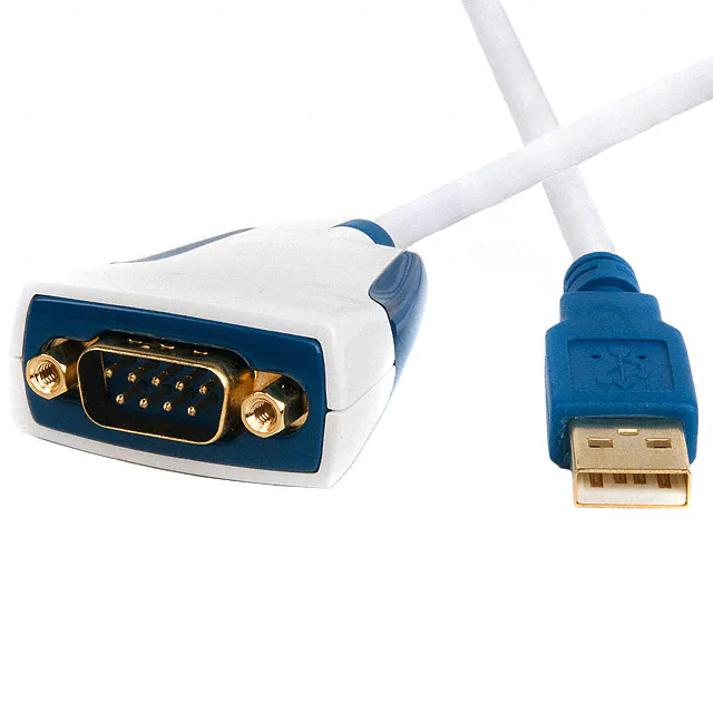
The USB-RS232 adaptor cables are a family of communication devices from FTDI Ltd. This model,
US232R, provides a simple method of adapting legacy serial devices with RS232 interfaces to modern
USB ports by incorporating the FTDI FT232R bridge chip.
The US232R cable is available in three lengths 10cm (US232R-10), 100cm (US232R-100)
and 500cm (US232R-500). Indicator LEDs provide status of Transmit (TX) and Receive
(Rx)
Future Technology Devices International Limited (FTDI)
Unit1, 2 Seaward Place, Centurion Business Park, Glasgow G41 1HH United Kingdom
Tel.: +44 (0) 141 429 2777 Fax: + 44 (0) 141 429 2758
E-Mail (Support): support1@ftdichip.com Web: http://www.ftdichip.com
System and equipment manufacturers and designers are responsible to ensure that their systems, and any Future
Technology Devices International Ltd (FTDI) devices incorporated in their systems, meet all applicable safety,
regulatory and system-level performance requirements. All application-related information in this document (including
application descriptions, suggested FTDI devices and other materials) is provided for reference only. While FTDI has
taken care to assure it is accurate, this information is subject to customer confirmation, and FTDI disclaims all liability
for system designs and for any applications assistance provided by FTDI. Use of FTDI devices in life support and/or
safety applications is entirely at the user’s risk, and the user agrees to defend, indemnify and hold harmless FTDI from
any and all damages, claims, suits or expense resulting from such use. This document is subject to change without
notice. No freedom to use patents or other intellectual property rights is implied by the publication of this document.
Neither the whole nor any part of the information contained in, or the product described in this document, may be
adapted or reproduced in any material or electronic form without the prior written consent of the copyright holder.
Future Technology Devices International Ltd, Unit 1, 2 Seaward Place, Centurion Business Park, Glasgow G41 1HH,
United Kingdom. Scotland Registered Company Number: SC136640
Copyright © 2011 Future Technology Devices International Limited
�Document Reference No.: FT_000151
DS_US232R-10(R-100/500) USB TO RS232 ADAPTER CABLE Data Sheet
Version 1.11
Clearance No.: #99
1
Introduction ................................................................................... 4
1.1
Functional Description .................................................................................. 4
1.2
Typical Applications ...................................................................................... 5
1.3
Driver Support .............................................................................................. 6
1.4
Block Diagram ............................................................................................... 7
1.4.1
2
3
Block description ....................................................................................... 7
1.5
Cable Features .............................................................................................. 8
1.6
Performance Figures ..................................................................................... 9
1.7
Ordering Information .................................................................................... 9
FT232R Key features .................................................................... 10
2.1.1
Integrated EEPROM ...................................................................................10
2.1.2
Pre-programmed EEPROM ..........................................................................10
2.1.3
Lower Operating and Suspend Current .........................................................10
2.1.4
Low USB Bandwidth Consumption ..............................................................10
2.1.5
UART Pin Signal Inversion .........................................................................10
2.1.6
FTDIChip-ID™ ..........................................................................................11
2.1.7
Improved EMI Performance .......................................................................11
2.1.8
Programmable Receive Buffer Timeout .........................................................11
2.1.9
Baud Rates ..............................................................................................11
Installation ................................................................................... 12
3.1
RS232 Connection Pin Out .......................................................................... 12
3.2
Device Driver Installation ........................................................................... 13
3.2.1
Microsoft Windows ....................................................................................13
3.2.2
Mac OS X, Linux, Windows CE ....................................................................16
Connections ....................................................................................... 17
3.3
4
5
3.3.1
USB ........................................................................................................17
3.3.2
RS232 .....................................................................................................17
Electrical details ........................................................................... 18
4.1
USB ............................................................................................................. 18
4.2
RS232 ......................................................................................................... 18
Mechanical Details ........................................................................ 19
5.1
6
External Connectors .................................................................................... 17
Module Mechanical Dimensions ................................................................... 19
Physical Environment Details ....................................................... 24
6.1
Operating .................................................................................................... 24
Copyright © 2011 Future Technology Devices International Limited
2
�Document Reference No.: FT_000151
DS_US232R-10(R-100/500) USB TO RS232 ADAPTER CABLE Data Sheet
Version 1.11
Clearance No.: #99
7
8
9
Environmental Approvals & Declarations ...................................... 25
7.1
EMI Compatibility ........................................................................................ 25
7.2
Safety ......................................................................................................... 25
7.3
Environmental ............................................................................................. 25
7.4
Reliability .................................................................................................... 25
Troubleshooting ........................................................................... 26
8.1
Hardware .................................................................................................... 26
8.2
Device Driver .............................................................................................. 26
Contact Information ..................................................................... 27
Appendix A - List of Figures and Tables ............................................. 28
Appendix B - Revision History ............................................................ 29
Copyright © 2011 Future Technology Devices International Limited
3
�Document Reference No.: FT_000151
DS_US232R-10(R-100/500) USB TO RS232 ADAPTER CABLE Data Sheet
Version 1.11
Clearance No.: #99
1
Introduction
1.1 Functional Description
The USB-RS232 adaptor cables are a family of communication devices. This model, US232R, provides a
simple method of adapting legacy serial devices with RS232 interfaces to modern USB ports.
Each US232R adapter contains a small internal electronic circuit board which utilises the FTDI FT232R,
mounted inside a rugged plastic enclosure capable of withstanding industrial temperature ranges. The
integrated electronics also include RS232 level shifters and TXD/RXD LEDs to provide a visual indication
of data traffic through the adapter.
The Cable incorporates a standard USB-A device connector for connection to an upstream host or hub
port. RS232-level signals, including modem handshake signals, are available on an industry-standard
DE-9P connector. The maximum RS232-level data rate is 1MBaud.
The US232R adapter cable requires USB device drivers, available free from FTDI, which are used to make
the US232R appear as a Virtual COM Port (VCP). This allows existing serial communications software,
such as HyperTerminal, to exchange data through the US232R to a legacy RS232 peripheral device.
Copyright © 2011 Future Technology Devices International Limited
4
�Document Reference No.: FT_000151
DS_US232R-10(R-100/500) USB TO RS232 ADAPTER CABLE Data Sheet
Version 1.11
Clearance No.: #99
1.2 Typical Applications
USB to RS232 Converter
Upgrading Legacy Peripherals to USB
USB Audio and Low Bandwidth Video data transfer
PDA to USB data transfer
USB Smart Card Readers
USB Instrumentation
USB Industrial Control
USB MP3 Player Interface
USB FLASH Card Reader / Writers
Set Top Box PC - USB interface
USB Digital Camera Interface
USB Hardware Modems
USB Wireless Modems
USB Bar Code Readers
USB Software / Hardware Encryption Dongles
Copyright © 2011 Future Technology Devices International Limited
5
�Document Reference No.: FT_000151
DS_US232R-10(R-100/500) USB TO RS232 ADAPTER CABLE Data Sheet
Version 1.11
Clearance No.: #99
1.3 Driver Support
Windows Vista x64
Windows XP x64
Windows Server 2003 x64
Windows Vista
Windows XP
Windows Server 2003
Windows 2000
Windows ME
Windows 98
Linux
Mac OS X
Mac OS 9
Mac OS 8
Windows CE.NET (Version 4.2 and greater)
The drivers listed above are all available to download for free from the FTDI website. Various 3rd Party
Drivers are also available for various other operating systems - see the FTDI website for details.
Copyright © 2011 Future Technology Devices International Limited
6
�Document Reference No.: FT_000151
DS_US232R-10(R-100/500) USB TO RS232 ADAPTER CABLE Data Sheet
Version 1.11
Clearance No.: #99
1.4 Block Diagram
USB A
Connector
Cable 10cm
or 100 cm
FTDI FT232R
USB Serial Bridge
RS232
Level Shifter
RS232
DE-9P
Connector
Figure 1-1 Block diagram
1.4.1 Block description
USB A Connector
This connector provides the interface for connection to a USB Host or Hub port
Cable
The US232R cable is available in three lengths 10cm – Part number US232R-10, 100cm - Part
number US232R-100 and 500cm - Part number US232R-500.
FTDI FT232R
The FTDI FT232R provides the USB-to-Serial conversion. Operating system device drivers are
required in order to work with the FT232R to provide the Virtual COM Port serial functionality.
RS232 Level Shifter
The RS232 level shifter converts the signals provided by the FT232R into the voltage levels
required by RS232 devices.
DE-9P Connector (Male)
The DE-9P connector is configured in an industry standard (TIA/EIA-574) pin-out to provide
connection to RS232 peripherals through standard cables. See section 3.3.2
Copyright © 2011 Future Technology Devices International Limited
7
�Document Reference No.: FT_000151
DS_US232R-10(R-100/500) USB TO RS232 ADAPTER CABLE Data Sheet
Version 1.11
Clearance No.: #99
1.5 Cable Features
Adds one RS-232 serial port by connecting to USB
Special high gloss white finish enclosure design
Side-lit blue RXD and TXD traffic indicators
Enhanced RS232 transceiver gives serial port speed of up to 1MBaud.
Gold plated USB and DB9 connectors for enhanced connection reliability
Integral 10cm (US232R-10) or 100cm (US232R-100) or 500cm (US232R-500) USB cable with
moulded strain relief
Quality 4-layer PCB design
Easy plug & play installation and RS-232 device connection
Works with USB 1.1 & 2.0 Host and Hub ports
Industry Standard FTDI chip set & device drivers for maximum compatibility
Microsoft Windows® WHQL-certified, Mac OS X, Linux and Windows CE device drivers
Installs as a standard Windows COM port
COM port number can be changed to any available COM port number, including COM1 to COM4,
to support HyperTerminal, or any other serial communications software application running in
Windows
FIFO: 128 byte transmit buffer, 256 byte receive buffer
RS-232 data signals: TxD, RxD, RTS, CTS, DSR, DTR, DCD, RI, GND
Powered by USB port. No external power adapter required.
Serial Communication Parameters
o
Parity: None, Even, Odd
o
Data bits: 7, 8
o
Flow control: RTS/CTS , DSR/DTR, X-ON/X-OFF, None
o
Stop bits 1,2
Operating temperature of -20°C to +80°C
Copyright © 2011 Future Technology Devices International Limited
8
�Document Reference No.: FT_000151
DS_US232R-10(R-100/500) USB TO RS232 ADAPTER CABLE Data Sheet
Version 1.11
Clearance No.: #99
1.6 Performance Figures
Parameter
Performance
USB Interface
12Mbps USB 2.0 Full-Speed
Standard Windows baud rates (300bps to 921.6Kbps)
RS232 Interface
Custom baud rates (300bps to 1Mbps) through baud rate aliasing. See
FTDI Application Note: Configuring FT232R, FT2232 and FT232BM Baud
Rates
Table 1.1 Performance Figures
1.7 Ordering Information
Part Number
Description
US232R-10
USB-RS232 Adapter Cable – 10cm cable length
US232R-100
USB-RS232 Adapter Cable – 100cm cable length
US232R-500
USB-RS232 Adapter Cable – 500cm cable length
Table 1.2 Ordering Information
Copyright © 2011 Future Technology Devices International Limited
9
�Document Reference No.: FT_000151
DS_US232R-10(R-100/500) USB TO RS232 ADAPTER CABLE Data Sheet
Version 1.11
Clearance No.: #99
2
FT232R Key features
This section summarises the key features and enhancements of the FT232R IC device which
is used on the US232R USB to RS232 converter cable. For further details, consult the
FT232R datasheet, which is available from the FTDI website.
2.1.1 Integrated EEPROM
Previous generations of FTDI’s USB UART devices required an external EEPROM if the
device were to use USB Vendor ID (VID), Product ID (PID), serial number and product
description strings other than the default values in the device itself. This external EEPROM
has now been integrated onto the FT232R chip meaning that all designs have the option to
change the product description strings. A user area of the internal EEPROM is available for
storing additional data. The internal EEPROM is programmable in circuit, over USB without
any additional voltage requirement.
2.1.2 Pre-programmed EEPROM
The FT232R is supplied with its internal EEPROM pre-programmed with a serial number
which is unique to each individual device. This, in most cases, will remove the need to
program the device EEPROM.
2.1.3
Lower Operating and Suspend Current
The device operating supply current has been further reduced to 15mA,
and the suspend current has been reduced to around 70μA. This allows greater margin for
peripheral designs to meet the USB suspend current limit of 500μA.
2.1.4
Low USB Bandwidth Consumption
The operation of the USB interface to the FT232R has been designed to use as little as
possible of the total USB bandwidth available from the USB host controller.
2.1.5
UART Pin Signal Inversion
The sense of each of the eight UART signals can be individually inverted by setting
options in the internal EEPROM. Thus, CTS# (active low) can be changed to CTS (active
high), or TXD can be changed to TXD#.
Copyright © 2011 Future Technology Devices International Limited
10
�Document Reference No.: FT_000151
DS_US232R-10(R-100/500) USB TO RS232 ADAPTER CABLE Data Sheet
Version 1.11
Clearance No.: #99
2.1.6
FTDIChip-ID™
Each FT232R is assigned a unique number which is burnt into the device at manufacture. This ID
number cannot be reprogrammed by product manufacturers or end-users. This allows the
possibility of using FT232R based dongles for software licensing. Further to this, a renewable
license scheme can be implemented based on the FTDIChip-ID™ number when encrypted
with other information. This encrypted number can be stored in the user area of the FT232R
internal EEPROM, and can be decrypted, then compared with the protected FTDIChip-ID™ to
verify that a license is valid. Web based applications can be used to maintain product
licensing this way. An application note describing this feature is available separately from the
FTDI website.
2.1.7
Improved EMI Performance
The reduced operating current and improved on-chip VCC decoupling significantly
improves the ease of PCB design requirements in order to meet FCC, CE and other EMI
related specifications.
2.1.8
Programmable Receive Buffer Timeout
The receive buffer timeout is used to flush remaining data from the
receive buffer. This time defaults to 16ms, but is programmable over USB in 1ms increments
from 1ms to 255ms, thus allowing the device to be optimised for protocols that require fast
response times from short data packets.
2.1.9
Baud Rates
The FT232R supports all standard baud rates and non-standard baud rates from 300
Baud up to 3 Mbaud. Achievable non-standard baud rates are calculated as follows Baud Rate = 3000000 / (n + x)
where n can be any integer between 2 and 16,384 ( = 214 ) and x can be a sub-integer of the value
0, 0.125, 0.25, 0.375, 0.5, 0.625, 0.75, or 0.875. When n = 1, x = 0, i.e. baud rate divisors with
values between 1 and 2 are not possible.
This gives achievable baud rates in the range 183.1 baud to 3,000,000 baud. When a nonstandard baud rate is required simply pass the required baud rate value to the driver as
normal, and the FTDI driver will calculate the required divisor, and set the baud rate. See
FTDI application note AN232B-05 for more details
The US232R cable is limited to a maximum of 1 Mbaud because of the line driver within
the circuit.
Copyright © 2011 Future Technology Devices International Limited
11
�Document Reference No.: FT_000151
DS_US232R-10(R-100/500) USB TO RS232 ADAPTER CABLE Data Sheet
Version 1.11
Clearance No.: #99
3
Installation
3.1 RS232 Connection Pin Out
Figure 3-1 RS232 DB9 Pin Out
DB9 Pin No.
Name
Type
Description
1
DCD
Input
Data Carrier Detect control input
2
RXDATA
Input
Receive Asynchronous Data input.
3
TXDATA
Output
Transmit Asynchronous Data output.
4
DTR
Output
Data Terminal Ready control output / Handshake signal
5
GND
Gnd
Device groud supply pin.
6
DSR
Input
Data Set Ready control input / Handshake signal
7
RTS
Output
Request To Send Control Output / Handshake signal
8
CTS
Input
Clear to Send Control input / Handshake signal.
9
RI
Input
Ring Indicator control input. When remote wakeup is
enabled in the FT232RL’s internal EEPROM taking RI#
low can be used to resume the PC USB host controller
from suspend.
Copyright © 2011 Future Technology Devices International Limited
12
�Document Reference No.: FT_000151
DS_US232R-10(R-100/500) USB TO RS232 ADAPTER CABLE Data Sheet
Version 1.11
Clearance No.: #99
3.2 Device Driver Installation
The US232R adaptor drivers are available for download from:
www.ftdichip.com
3.2.1 Microsoft Windows
With the device drivers being Windows Hardware Quality Labs (WHQL) certified, they are also available
through download directly from the Microsoft® Windows® Update service. This is the best choice when
connecting the US232R to a computer running Windows Vista. Additional installation options are noted
below:
Installation Executable on Windows XP
1) Login to your system as Administrator, or a user with Administrator rights.
2) Prior to connecting the US232R to the USB Host or Hub port, download the latest device driver
version from the FTDI web site.
3) Run this executable to install the device drivers.
4) Connect the US232R to your computer. A notification will appear near the task bar indicating
that new hardware has been installed and is ready for use. It is normal if this notice appears
twice.
Figure 3-2 Hardware Ready
Windows Update shown on Windows XP
You must have an active Internet connection and the Windows Update Service enabled.
1) Connect the US232R to your USB Host or Hub.
2) The “Found New Hardware” Wizard will appear. The first dialog should ask whether it is
acceptable to use the Windows Update Service to find the device driver.
Figure 3-3 Found New Hardware Wizard
3) Select one of the “Yes” choices and click “Next”.
4) The following screen appears:
Copyright © 2011 Future Technology Devices International Limited
13
�Document Reference No.: FT_000151
DS_US232R-10(R-100/500) USB TO RS232 ADAPTER CABLE Data Sheet
Version 1.11
Clearance No.: #99
Figure 3-4 Automatic Install
5) Wait while the driver is found, downloaded, and installed. This step may take a couple minutes
depending on the Internet speed.
6) After the files are found and installed, click “Finish” to complete the installation.
Figure 3-5 Complete Hardware Installation
7) Steps 2 through 6 will repeat. The first time installs the basic USB Serial Converter in the USB
device tree. The second time installs the Virtual COM Port layer in the Ports tree and assigns the
COM port number.
8) When both portions of the device driver have been installed successfully, the following message
will appear, indicating that the device is ready.
Figure 3-6 Hardware Ready
Copyright © 2011 Future Technology Devices International Limited
14
�Document Reference No.: FT_000151
DS_US232R-10(R-100/500) USB TO RS232 ADAPTER CABLE Data Sheet
Version 1.11
Clearance No.: #99
COM Port Assignment
Next, to determine which COM port has been assigned, open the Windows Device Manager from the
System Control Panel.
Figure 3-7 Device Manager
Click on the Plus “+” sign next to the Ports tree to list the available COM port. You will see “FTDI USB
COM Port”, followed by a COMn assignment. In the figure below, the US232R is assigned to COM3.
Figure 3-8 COM Port Assignment
Use this COM port number with your application software in order to access the US232R.
If an application requires use of a different COM port number, the assignment may be changed through
the Advanced Driver Options settings.
From the Device Manager listing above, right-click on the FTDI USB COM Port and select Properties.
Figure 3-9 Access COM Port Properties
Next, click on the “Port Settings” tab.
Copyright © 2011 Future Technology Devices International Limited
15
�Document Reference No.: FT_000151
DS_US232R-10(R-100/500) USB TO RS232 ADAPTER CABLE Data Sheet
Version 1.11
Clearance No.: #99
Figure 3-10 Settings Tab
Then click on the “Advanced…” button.
Figure 3-11 Advanced Options
This will display the various advanced settings. Note the COM port assignment in the upper left. Clicking
on the drop-down list will display the available port numbers. Select one that is not in use and click OK
on each dialog box to activate the selection. Windows will remember this COM port number.
3.2.2 Mac OS X, Linux, Windows CE
Device drivers and FTDI installation guides for Mac OS X, Linux and Windows CE are available for
download on the FTDI web site. Follow the respective FTDI installation guides for the chosen operating
system.
Copyright © 2011 Future Technology Devices International Limited
16
�Document Reference No.: FT_000151
DS_US232R-10(R-100/500) USB TO RS232 ADAPTER CABLE Data Sheet
Version 1.11
Clearance No.: #99
Connections
3.3 External Connectors
3.3.1 USB
The USB-F-1001 is a downstream USB 2.0 Device. A standard USB Series “A” connector is mounted
inside the USB-F-1001 to facilitate connection to an upstream USB Host or Hub.
Pin Number
Pin Type
Description
1
Power
2
Bidirectional
D– = USB data signal, negative polarity
3
Bidirectional
D+ = USB data signal, positive polarity
4
Ground
Shield
Case Ground
VBUS – USB Power provided from upstream USB Host or Hub
GND = USB signal ground
Drain = typically connected to the host PC case
Table 3.1 USB "A" Connector Pin-Out
3.3.2 RS232
The RS232 port is configured as Data Terminal Equipment (DTE), with a 9-contact D-Sub Pin connector.
Pin assignments are according to TIA/EIA-574 which formally defines the assignments for a COM port
found on many personal computers.
Pin Number
Pin Type
Description
1
Input
DCD = Data Carrier Detect
2
Input
RXD = Receive Data
3
Output
TXD = Transmit Data
4
Output
DTR = Data Terminal Ready
5
Ground
GND = RS232 signal ground
6
Input
DSR = Data Set Ready
7
Output
RTS = Request To Send
8
Input
9
Input / Power
RI = Ring Indicator
Shield
Case Ground
Drain = typically connected to the host PC case
CTS = Clear To Send
Table 3.2 DE-9P RS232 Pin-Out
Copyright © 2011 Future Technology Devices International Limited
17
�Document Reference No.: FT_000151
DS_US232R-10(R-100/500) USB TO RS232 ADAPTER CABLE Data Sheet
Version 1.11
Clearance No.: #99
4
Electrical details
4.1 USB
Parameter
Description
Minimum
Typical
Maximum
Units
Conditions
*Present when USB
USB_VCC
Input Power Voltage*
4.25
5.0*
5.25
V
cable is attached and
USB Host or Hub
powered.
Icc
USB current
30
50
mA
Typical
Maximum
Units
Table 4.1 USB Electrical Details
4.2 RS232
Parameter
Vtrans
Vrec
Description
Transmitter output
voltage swing
Receiver input voltage
range
ESD HBM
Minimum
±5
±2.4
±25
±15
Conditions
V
RL = 3KΩ
V
Input resistance = 3KΩ
to 7KΩ
KV
RS-232 Inputs and
Outputs
Table 4.2 RS232 Electrical Details
Copyright © 2011 Future Technology Devices International Limited
18
�Document Reference No.: FT_000151
DS_US232R-10(R-100/500) USB TO RS232 ADAPTER CABLE Data Sheet
Version 1.11
Clearance No.: #99
5
Mechanical Details
5.1 Module Mechanical Dimensions
Figure 5-1 Cable Dimensions
Copyright © 2011 Future Technology Devices International Limited
19
�Document Reference No.: FT_000151
DS_US232R-10(R-100/500) USB TO RS232 ADAPTER CABLE Data Sheet
Version 1.11
Clearance No.: #99
Figure 5-2 Case top Dimensions
Copyright © 2011 Future Technology Devices International Limited
20
�Document Reference No.: FT_000151
DS_US232R-10(R-100/500) USB TO RS232 ADAPTER CABLE Data Sheet
Version 1.11
Clearance No.: #99
Figure 5-3 Case Base Dimensions
Copyright © 2011 Future Technology Devices International Limited
21
�Document Reference No.: FT_000151
DS_US232R-10(R-100/500) USB TO RS232 ADAPTER CABLE Data Sheet
Version 1.11
Clearance No.: #99
Figure 5-4 Cap Dimensions
Copyright © 2011 Future Technology Devices International Limited
22
�Document Reference No.: FT_000151
DS_US232R-10(R-100/500) USB TO RS232 ADAPTER CABLE Data Sheet
Version 1.11
Clearance No.: #99
Figure 5-5 Lens Dimensions
Copyright © 2011 Future Technology Devices International Limited
23
�Document Reference No.: FT_000151
DS_US232R-10(R-100/500) USB TO RS232 ADAPTER CABLE Data Sheet
Version 1.11
Clearance No.: #99
6
Physical Environment Details
6.1 Operating
Parameter
T
Description
Operating Temperature
Range
Minimum
–20
Typical
Maximum
+80
Units
o
C
Conditions
5% to 95% RH,
non condensing
Table 6.1 Operating Temperature
Copyright © 2011 Future Technology Devices International Limited
24
�Document Reference No.: FT_000151
DS_US232R-10(R-100/500) USB TO RS232 ADAPTER CABLE Data Sheet
Version 1.11
Clearance No.: #99
7
Environmental Approvals & Declarations
7.1 EMI Compatibility
FCC and CE
The US232R has been tested to be compliant with both FCC Part 15 Subpart B and European EMC
Directive.
NOTE: This is a Class B product. In a domestic environment, this product may cause radio interference,
in which case the user may be required to take adequate measures.
NOTE: This equipment has been tested and found to comply with the limits for a Class B digital device,
pursuant to Part 15 of the FCC Rules. These limits are designed to provide reasonable protection against
harmful interference in a residential installation. This equipment generates, uses and can radiate radio
frequency energy and, if not installed and used in accordance with the instructions, may cause harmful
interference to radio communications. However, there is no guarantee that interference will not occur in a
particular installation. If this equipment does cause harmful interference to radio or television reception,
which can be determined by turning the equipment off and on, the user is encouraged to try to correct
the interference by one or more of the following measures:
Reorient or relocate the receiving antenna.
Increase the separation between the equipment and receiver.
Connect the equipment into an outlet on a circuit different from that to which the receiver is
connected.
Consult the dealer or an experienced radio/TV technician for help.
7.2 Safety
The US232R is defined as Limited Power Supply (LPS) device, with operating voltages under 60VDC.
7.3 Environmental
The US232R is a lead-free device that complies with the following environmental directives: RoHS, WEEE,
REACH, PFOS and DecaBDE.
7.4 Reliability
The US232R is designed as a robust USB-Serial adapter for use in many environments. There are no
user-serviceable parts. Any failure will require a replacement of the unit.
Copyright © 2011 Future Technology Devices International Limited
25
�Document Reference No.: FT_000151
DS_US232R-10(R-100/500) USB TO RS232 ADAPTER CABLE Data Sheet
Version 1.11
Clearance No.: #99
8
Troubleshooting
8.1 Hardware
Cables are the most common sources of trouble with external devices.
Check the following:
-
USB cable is properly inserted
-
Computer power is ON
-
Computer is not in Sleep or Standby
-
If a USB Hub is used, be sure it is set for “Self-Powered” operation
-
If a USB Hub is used, be sure all cables are properly inserted
RS232 cables – check the following:
-
Output signals (TXD, RTS, DTR) are connected to the respective inputs (RXD, CTS, DSR) in each
direction.
-
Check for specific handshake requirements of your RS232 peripheral.
-
If handshake signals are not used, ensure the application is set to “No Hardware Handshake”, or
equivalent.
-
Test the port with a loop-back connector. Connect TXD to RXD, RTS to CTS and DTR to DSR. Use a
simple terminal program (e.g. HyperTerminal) to check that data is transmitted and received.
8.2 Device Driver
Ensure the latest device driver is in use. See www.ftdichip.com
If other devices with FTDI chips are installed in the system, check with all manufacturers of these devices
for the latest device drivers.
See the FTDI installation guides for additional details: http://ftdichip.com/Documents/InstallGuides.htm
Common Windows Device Driver Troubles:
DEVICE TIMES OUT: The default settings of the device driver assume typical data transfers of
hundred to thousands or more bytes at a given time. Some applications, such as a GPS device,
only send data in short packets, often only a few bytes. If this is the case, it may be necessary
to adjust the drivers buffer size and/or latency timer to smaller values. These values can be
adjusted through the Advanced driver options as noted in Figure 2.13. The buffer size can be
reduced to 64 bytes. The latency timer can be set as low as 2ms. A setting of 1ms will cause
unnecessary USB traffic and could adversely affect data transmission.
ERRATIC MOUSE POINTER: The device driver defaults to query an attached device to find out
whether it is a mouse or modem, consistent with native COM port operation. Some RS232
peripherals constantly send short packets of data, causing the host system to “think” a mouse or
modem has been attached. These short packets will interfere with normal mouse operation
causing the pointer to jump around the screen. If this happens, disconnect the RS232 device and
uncheck the Serial Enumerator option, also found on the Advanced driver options screen in Figure
2.13.
COM PORT IN USE: Windows keeps track of all COM port assignments. If multiple FTDI products
have been connected to a single system, the COM port number will increase, even if the other
devices are not attached. If the higher COM port assignments are not acceptable for the
application, known unused COM port numbers should be uninstalled according to the FTDI
installation guide: http://ftdichip.com/Documents/InstallGuides.htm.
Copyright © 2011 Future Technology Devices International Limited
26
�Document Reference No.: FT_000151
DS_US232R-10(R-100/500) USB TO RS232 ADAPTER CABLE Data Sheet
Version 1.11
Clearance No.: #99
9
Contact Information
Head Office – Glasgow, UK
Future Technology Devices International Limited
Unit 1, 2 Seaward Place, Centurion Business Park
Glasgow G41 1HH
United Kingdom
Tel: +44 (0) 141 429 2777
Fax: +44 (0) 141 429 2758
E-mail (Sales)
E-mail (Support)
E-mail (General Enquiries)
Web Site URL
Web Shop URL
sales1@ftdichip.com
support1@ftdichip.com
admin1@ftdichip.com
http://www.ftdichip.com
http://www.ftdichip.com
Branch Office – Taipei, Taiwan
Future Technology Devices International Limited (Taiwan)
2F, No. 516, Sec. 1, NeiHu Road
Taipei 114
Taiwan , R.O.C.
Tel: +886 (0) 2 8791 3570
Fax: +886 (0) 2 8791 3576
E-mail (Sales)
E-mail (Support)
E-mail (General Enquiries)
Web Site URL
tw.sales1@ftdichip.com
tw.support1@ftdichip.com
tw.admin1@ftdichip.com
http://www.ftdichip.com
Branch Office – Hillsboro, Oregon, USA
Future Technology Devices International Limited (USA)
7235 NW Evergreen Parkway, Suite 600
Hillsboro, OR 97123-5803
USA
Tel: +1 (503) 547 0988
Fax: +1 (503) 547 0987
E-Mail (Sales)
E-Mail (Support)
E-Mail (General Enquiries)
Web Site URL
us.sales@ftdichip.com
us.support@ftdichip.com
us.admin@ftdichip.com
http://www.ftdichip.com
Branch Office – Shanghai, China
Future Technology Devices International Limited (China)
Room 408, 317 Xianxia Road,
Shanghai, 200051
China
Tel: +86 21 62351596
Fax: +86 21 62351595
E-mail (Sales)
E-mail (Support)
E-mail (General Enquiries)
Web Site URL
cn.sales@ftdichip.com
cn.support@ftdichip.com
cn.admin@ftdichip.com
http://www.ftdichip.com
Distributor and Sales Representatives
Please visit the Sales Network page of the FTDI Web site for the contact details of our distributor(s) and
sales representative(s) in your country.
Copyright © 2011 Future Technology Devices International Limited
27
�Document Reference No.: FT_000151
DS_US232R-10(R-100/500) USB TO RS232 ADAPTER CABLE Data Sheet
Version 1.11
Clearance No.: #99
Appendix A - List of Figures and Tables
List of Figures
Figure 1-1 Block diagram .................................................................................................................................7
Figure 3-1 RS232 DB9 Pin Out ......................................................................................................................12
Figure 3-2 Hardware Ready ...........................................................................................................................13
Figure 3-3 Found New Hardware Wizard ......................................................................................................13
Figure 3-4 Automatic Install ..........................................................................................................................14
Figure 3-5 Complete Hardware Installation .................................................................................................14
Figure 3-6 Hardware Ready ...........................................................................................................................14
Figure 3-7 Device Manager ............................................................................................................................15
Figure 3-8 COM Port Assignment .................................................................................................................15
Figure 3-9 Access COM Port Properties ......................................................................................................15
Figure 3-10 Settings Tab ................................................................................................................................16
Figure 3-11 Advanced Options......................................................................................................................16
Figure 5-1 Cable Dimensions ........................................................................................................................19
Figure 5-2 Case top Dimensions ...................................................................................................................20
Figure 5-3 Case Base Dimensions ................................................................................................................21
Figure 5-4 Cap Dimensions ...........................................................................................................................22
Figure 5-5 Lens Dimensions ..........................................................................................................................23
List of Tables
Table 1.1 Performance Figures .......................................................................................................................9
Table 1.2 Ordering Information .......................................................................................................................9
Table 3.1 USB "A" Connector Pin-Out .........................................................................................................17
Table 3.2 DE-9P RS232 Pin-Out.....................................................................................................................17
Table 4.1 USB Electrical Details ....................................................................................................................18
Table 4.2 RS232 Electrical Details ................................................................................................................18
Table 6.1 Operating Temperature .................................................................................................................24
Copyright © 2011 Future Technology Devices International Limited
28
�Document Reference No.: FT_000151
DS_US232R-10(R-100/500) USB TO RS232 ADAPTER CABLE Data Sheet
Version 1.11
Clearance No.: #99
Appendix B - Revision History
Draft
Initial Draft – subject to change
07-07-2009
Rev 1.0
Initial Release
04-08-2009
Rev 1.1
Added part number US232R-500 and modified disclaimer
13-01-2011
Rev 1.11
Edited that the US232R cable is available in three lengths
25-01-2011
Copyright © 2011 Future Technology Devices International Limited
29
�


 工商网监
湘ICP备2023018690号
工商网监
湘ICP备2023018690号
