Varistor Products
Industrial High Energy Terminal Varistors > DHB34 Series
RoHS
DHB34 Varistor Series
Description
The DHB34 Series of transient surge suppressors is
comprised of two industrial high-energy Metal-Oxide
Varistors (MOVs) discs placed in parallel as a single device.
They are designed to provide surge suppression in the
AC mains outdoor and service entrance environment
(distribution panels) of buildings. DHB34 applications
also include industrial heavy motors, controls, and power
supplies such as used in the oil-drilling, mining, and
transportation fields, including HVAC and motor/generator
applications.
The DHB34 Series provides rigid terminals for throughhole solder mounting on printed circuit boards, thereby
eliminating the need for screw mounting.
Agency Approvals
Agency
Agency File Number
Features
1449, E320116, 1414, E56529
-3�����
t� �-FBE�'SFF
�)BMPHFO�
'SFF�BOE�3P)4�
Compliant
t� 3JHJE�UFSNJOBMT�GPS�
secure through-hole
solder mounting
t� 8JEF�PQFSBUJOH�
voltage range
t� /P�EFSBUJOH�VQ�UP�
85ºC ambient
V. "$
3.4 110V to 750V
t� )JHIoFOFSHZ�
absorption
capability
8TM = 220J to 1050J
t� %VBM�%JTD�%FWJDF���
two 34mm varistor
discs in parallel in
B�TJOHMF�QBDLBHF�
HI–ENERGY
DHB34MOV’S
Series
t� )JHI�QFBL�QVMTF�
current (Each of
two discs placed in
parallel) capability
ITM = 40,000A
Absolute Maximum Ratings
t�'PS�SBUJOHT�PG�JOEJWJEVBM�NFNCFST�PG�B�TFSJFT
�TFF�%FWJDF�3BUJOHT�BOE�4QFDJmDBUJPOT�DIBSU
Continuous
DHB34 Series
Units
"$�7PMUBHF�3BOHF� 7. "$
3.4)
110 to 750
V
%$�7PMUBHF�3BOHF� 7M(DC))
148 to 970
V
40000
A
Steady State Applied Voltage:
Transients:
1FBL�1VMTF�$VSSFOU� *TM)
'PS�����μT�$VSSFOU�8BWF� 4FF�'JHVSF��
4JOHMF�1VMTF�&OFSHZ�3BOHF
'PS��NT�$VSSFOU�8BWF� 8TM)
220 to 1050
J
0QFSBUJOH�"NCJFOU�5FNQFSBUVSF�3BOHF� 5A)
-55 to + 85
ºC
4UPSBHF�5FNQFSBUVSF�3BOHF� 5STG)
-55 to + 125
ºC
Temperature Coefficient (aV) of Clamping Voltage (VC) at Specified Test Current
DHB34 Series
Dimensions (mm)
T max
Table of Dimensions - Thickness and Terminal Offsets
56 max
12.7 typ
3.7 typ
Dia 3.81 +/- 0.08
25.4 +/- 0.5
S1
S2
0.51 typ
B
A
C
Terminals
Configuration
7.06 +/- 0.2
MOV1
MOV2
/05&4��
- Terminals Configuration:
Terminals A & B are connected to one varistor element.
Terminals B & C connected to second varistor element.
- Dimensions:
Measures are in mm is typical, unless otherwise specified.
Part Type
T Max
S1 +/- 1.15
mm
S2 +/2.30mm
V111DHB34
7.6
2.65
5.50
V131DHB34
7.8
2.85
5.70
V141DHB34
8.2
3.00
6.00
V151DHB34
8.8
3.15
6.30
V181DHB34
9.0
3.25
6.50
V201DHB34
9.2
3.35
6.70
V251DHB34
9.10
3.00
6.00
V271DHB34
9.55
3.25
6.50
V301DHB34
10.20
3.50
7.00
V321DHB34
10.60
3.66
7.24
V331DHB34
10.65
3.70
7.40
V351DHB34
10.5
4.10
8.20
V391DHB34
11.2
4.45
8.90
V421DHB34
12.65
4.50
9.00
V441DHB34
12.80
4.55
9.10
V481DHB34
13.55
4.80
9.60
V511DHB34
13.4
5.25
10.50
V551DHB34
14.6
5.70
11.40
V571DHB34
14.8
5.80
11.60
V661DHB34
17.20
6.65
13.30
V681DHB34
17.5
7.00
14.00
V751DHB34
18.20
7.35
14.70
HI–ENERGY
DHB34MOV’S
Series
37.5 max
Part Numbering System
V 13 1DHB 34
VARISTOR DESIGNATOR
MAX AC RMS WORKING VOLTAGE
(FIRST SIGNIFICANT DIGITS) V M(AC)
DISC SIZE (mm)
SERIES DESIGNATOR
VM(AC) VOLTAGE DECADE MULTIPLIER
©2010 Littelfuse, Inc.
Specifications are subject to change without notice.
Please refer to www.littelfuse.com/series/dhb34.html for current information.
DHB34 Varistor Series
Revision: October 19, 2010
�
很抱歉,暂时无法提供与“V271DHB34”相匹配的价格&库存,您可以联系我们找货
免费人工找货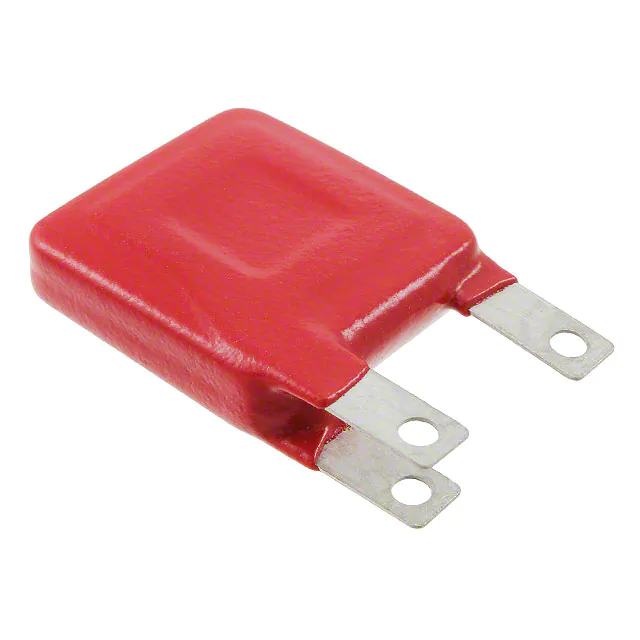


 工商网监
湘ICP备2023018690号
工商网监
湘ICP备2023018690号
