The product information in this catalog is for reference only. Please request the Engineering Drawing for the most current and accurate design information. All non-RoHS products have been discontinued, or will be discontinued soon. Please check the products status on the Hirose website RoHS search at www.hirose-connectors.com, or contact your Hirose sales representative.
1mm Pitch Cable-to-Board Connectors supporting LVDS signal
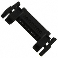
FX15 Series
Space saving, Equal length transmission lines
Patent pending
Termination side: 0.5 mm pitch, 1-row construction Mating side: 1 mm pitch, staggered 2-row construction Contacts consolidated into 1 row for equal length transmission lines
Fig.1
sFeatures
1. Space saving
Reduction in space is achieved by designing the contacts in 2-row staggered 1 mm pitch on the mating side and on a single row 0.5 mm pitch on the termination side (Fig. 1).
Self-alignment of ±1.5 mm
Large guide post 1.5mm
2. Equal length transmission lines
Contact configuration creates equal length transmission lines preventing deterioration of LVDS signal within the connector (Fig.1).
1.5mm
Fig.2
3. Different types
Availability of types with or without metal shields allows flexibility of applications and cost reduction.
Side latch -locks
4. Self alignment and self-guiding
Built-in guide posts allow secure self-alignment within ±1.5 mm (Fig.2).
5. Secure and complete mating / unmating
S ide latch-locks assure and confirm complete and secure mating of plugs to receptacles while permitting ease of disconnection (Fig. 3).
6. Enhanced shielding effectiveness
A vailability of version with enlarged metal shields (preventing intrusion or emission of the electromagnetic interference) further protects the integrity of LVDS signal (FX15S series, Fig.4)
With metal shields (FX15 and FX15S Series)
Fig.3
Without metal shields (FX15M Series)
High Shielding Effectiveness
0
Emission Noise Level (dBm)
7. RoHS compliant
A ll components and materials comply with the reqirements of EU Directive 2002/95/EC.
Without metal -10 -20 With metal
sApplications
FPD-TV, FPD panels and other applications requiring secure and reliable connection and transmission signal integrity.
Fig.4
-30
-40
-50
0.1 0.2
0.3
0.5
1
1.5
2
3
Frequency (GHz)
B273
�The product information in this catalog is for reference only. Please request the Engineering Drawing for the most current and accurate design information. All non-RoHS products have been discontinued, or will be discontinued soon. Please check the products status on thesignal FX15 Seriesq1mm Pitch Cable-to-Board Connectors supporting LVDS Hirose website RoHS search at www.hirose-connectors.com, or contact your Hirose sales representative.
sProduct Specifications
Ratings Item 1. Contact resistance 2. Insulation resistance 3. Withstanding voltage 4. Insertion-Extraction force 5. Durability (mating/un-mating) 6. Vibration 7. Shock 8. Humidity Current rating Voltage rating
0.5A 100V AC
Operating temperature range Storage temperature range
-55ç to +80ç (Note 1) -10ç to +60ç (Note 2)
Specification 60 m ohms max. (Note 3) 500 M ohms min. No flashover or insulation breakdown. 0.2N min., 30N max. Contact resistance: 80 m ohms max.(Note 3) No electrical discontinuity of 1 µs or more. No electrical discontinuity of 1 µs or more. Contact resistance: 80 m ohms max. No damage, cracks, or parts dislocation.(Note 3) Contact resistance: 80 m ohms max. (Note 3) Insulation resistance: 500 M ohms min. Contact resistance: 80 m ohms max. (Note 3) No corrosions
Conditions 1 mA 100V DC 300V AC/one minute With corresponding connector 50 cycles Frequency: 10 to 55 Hz, single amplitude of 0.76mm, 2 hours, 3 axis Acceleration of 490m/s2, 11ms durations, sine half-wave waveform, 3 cycles, 3axis. 96 hours at 40ç, RH 90% to 95% Temperature : -55ç ¡ +15ç to +35ç ¡ +85ç ¡ +15ç to +35ç Time : 30 ¡ 5 ¡ 30 ¡ 5 (Minutes) 5 cycles 5% water solution for 48 hours.
9. Temperature cycle
10. Salt spray
Note 1: Includes temperature rise caused by current flow. Note 2: The term “storage” refers to products stored for long period of time prior to mounting and use. Operating temperature range and humidity range covers non-conducting condition of installed connectors in storage, shipment or during transportation. Note 3: Includes wire conductor resistance (12mm long). Note 4: Information contained in this catalog represents general requirements for this Series. Contact us for the drawings and specifications for a specific part number shown.
sMaterials and Finishes
qReceptacle
Component Insulator Contact Metal shields (with shields) Metal fittings (without shields) Material Polyamide Phosphor bronze FX15S : Nickel silver FX15SC : Stainless steel Phosphor bronze Finish Color: Black Contact area: Gold plated Termination area: Tin plated FX15S : --------------FX15SC : Tin plated Selective gold flash plated Remarks UL94V-0 -------------------------------------------
qPlug
Component Insulator Contact Metal shields (with shields) Metal latch-locks (with shields) Metal shields, metal latch-looks (micro-coaxial cable) Material Polyamide Phosphor bronze Nickel silver Stainless steel Stainless steel Finish Color: Black Contact area: Gold plated Termination area: Tin plated ----------------------------Nickel plated Remarks UL94V-0 --------------------------------------------------------: FX15 Blank : With shields (or crimp contact) 15S : With shields – enhanced shielding 15SC : With shields – enhanced shielding (PCB mounting pattern : VESA standard) 15M : Without shields P S : Male contact : Female contact : 0.5 mm SH : Right angle SV : Straight C : Crimp 0.5SD : Micro-coaxial cable GND : Separate ground plate 2830 : AWG 28 to 30 3032 : AWG 30 to 32 PCF : Reel/ plug contact B : Gold plated
sOrdering information
qReceptacle
1 Series Name 2 Configuration
FX15 S - 31 S - 0.5 SH
1 2 3 4 5 6 3 Number of contacts 4 Connector type 5 Contact pitch 6 Housing configuration 7 Termination
qPlug
FX15 S - 31 P - C
1 2 3 4 7
qCrimp contact
FX15 - 3032 PCF B
1 2 8 9 10
8 Applicable conductor 9 Packaging 10 Plating (contact area)
B274
�The product information in this catalog is for reference only. Please request the Engineering Drawing for the most current and accurate design information. All non-RoHS products have been discontinued, or will be discontinued soon. Please check the products status on the Hirose website RoHS search at www.hirose-connectors.com, or contact your Hirose sales representative. FX15 Seriesq1mm Pitch Cable-to-Board Connectors supporting LVDS signal
sFX15 Series – Mating Diagram
Crimp contact
Plugs
With shields-standard (FX15-31P-C)
Receptacles
Vertical, with shields (FX15-31S-0.5SV)
Crimp contact (FX15-3032-PCFB)
Without shields (FX15M-P-C)
With shields – enhanced shielding (FX15S-P-C)
Crimp contact (FX15-2830-PCFB)
With shields – enhanced shielding AWG#28 to 30 (FX15SW-31P-C)
B
Right angle, with shields –enhanced shielding (FX15S-S-0.5SH)
B
Right angle, without shields (FX15M-S-0.5SH)
B
With shields – enhanced shielding PCB mouting pattern : VESA standard (FX15SC-S-0.5SH)
28
Ground plate (FX15S-P-GND)
Micro-coaxial cable (FX15S-P-0.5SD)
With shields – enhanced shielding PCB mouting pattern : VESA standard (FX15SC-S-0.5SV)
Ragarding the availability of the positions, contact your nearest Hirose representative.
A
B275
�The product information in this catalog is for reference only. Please request the Engineering Drawing for the most current and accurate design information. All non-RoHS products have been discontinued, or will be discontinued soon. Please check the products status on thesignal FX15 Seriesq1mm Pitch Cable-to-Board Connectors supporting LVDS Hirose website RoHS search at www.hirose-connectors.com, or contact your Hirose sales representative.
sPlugs
qWith shields (FX15-31P-C)
Polarizing mark indicator
(27) 24.6±0.3 22.57±0.15
2.7±0.1
(13.45) 9.4±0.3
18.3±0.3 No.2 14±0.15 P=1±0.1 No.30
3.7±0.3
No.1
P=1±0.1 15±0.15
No.31
Part Part number FX15-31P-C
CL No. CL575-2101-2
Number of contacts 31
RoHS YES
Note 1: Packaged in trays. Note 2: Dimensions in parenthesis ( ) are reference dimensions.
qWith shields, enhanced shielding (FX15S-**P-C)
Polarizing mark indicator
(A) B±0.3 C±0.15
4±0.3 2.7±0.1
(13.45) 9.4±0.3
D±0.3 No.2 E±0.15 P=1±0.1 No.n-1
3.7±0.3
No.1
P=1±0.1 F±0.15
No.n
Part number FX15S-31P-C FX15S-41P-C FX15S-51P-C
CL No. CL575-2106-6 CL575-2107-9 CL575-2103-8
Number of contacts 31 41 51
A 27 32 37
B 24.6 29.6 34.6
C 22.6 27.6 32.6
D 18.3 23.3 28.3
E 14 19 24
F 15 20 25
RoHS YES
Note 1: Packaged in trays. Note 2: Dimensions in parenthesis ( ) are reference dimensions.
B276
�The product information in this catalog is for reference only. Please request the Engineering Drawing for the most current and accurate design information. All non-RoHS products have been discontinued, or will be discontinued soon. Please check the products status on the Hirose website RoHS search at www.hirose-connectors.com, or contact your Hirose sales representative. FX15 Seriesq1mm Pitch Cable-to-Board Connectors supporting LVDS signal
qWith shields – enhanced shielding
AWG#28 to 30 (FX15SW-31P-C)
Polarizing mark indicator
(27) 24.6±0.3 22.57±0.15
4±0.3 2.7±0.1
(13.45) 9.4±0.3
B 28
18.3±0.3 No.2 14±0.15 P=1±0.1
A
3.7±0.3 No.30
Part number FX15SW-31P-C
CL No. CL575-2113-1
Number of contacts 31
RoHS YES
No.1
P=1±0.1 15±0.15
No.31
Note 1: Packaged in trays. Note 2: Dimensions in parenthesis ( ) are reference dimensions.
qWithout shields (FX15M-**P-C)
Polarizing mark indicator
(A) B±0.3
(13) 9.55±0.3
C±0.3 (D) No.2 E±0.15 P=1±0.1 No.n-1
4.2±0.3
No.1
P=1±0.1 F±0.15
No.n
Part number FX15M-21P-C FX15M-31P-C
CL No. CL575-2109-4 CL575-2108-1
Number of contacts 21 31
A 24.8 29.8
B 20.5 25.5
C 17.6 22.6
D 13.7 18.7
E 25.8 30.8
F 9 14
G 10 15
(13.6)
RoHS YES
Note 1: Sold in package containing 100 pieces. Order by package. Note 2: Dimensions in parenthesis ( ) are reference dimensions.
B277
�The product information in this catalog is for reference only. Please request the Engineering Drawing for the most current and accurate design information. All non-RoHS products have been discontinued, or will be discontinued soon. Please check the products status on thesignal FX15 Seriesq1mm Pitch Cable-to-Board Connectors supporting LVDS Hirose website RoHS search at www.hirose-connectors.com, or contact your Hirose sales representative.
sPlug crimp contacts
Part number FX15-2830PCFB FX15-3032PCFB CL No. CL575-2002-0 CL575-2003-3 Packaging Reel Quantity 20,000 pieces per reel Finish Gold plated RoHS YES
qApplicable cable (Tin plated solid soft strands)
FX15-2830PCFB Applicable wire size (Stranded wire conductor) AWG #28 (7/0.127 mm) AWG #30 (7/0.1 mm) FX15-3032PCFB Applicable wire size (Stranded wire conductor) AWG #30 (7/0.1 mm) AWG #32 (7/0.08 mm) Jacket diameter Ø0.5 to 0.6mm UL No. 1516, 1571 (Note) 1571 Jacket diameter Ø0.56 to 0.72mm UL No.
0.72±0.1 0.35±0.1
1517 1571
0.9±0.15 0.5±0.15 t=0.15±0.05 2±0.15 (7)
qWire strip length: 1.1 to 1.8 mm
Note: When using other than the recommended wire, contact your nearest Hirose representative.
qTools
Item Applicator Press unit Product number AP105-FX15-2830 AP105-FX15-3032 CM-105 CL No. 901-4036-0 901-4033-1 901-0005-4 Applicable crimp contact FX15-2830PCFB FX15-3032PCFB –––––––––
Note: Consult HRS representative when using applicator.
B278
�The product information in this catalog is for reference only. Please request the Engineering Drawing for the most current and accurate design information. All non-RoHS products have been discontinued, or will be discontinued soon. Please check the products status on the Hirose website RoHS search at www.hirose-connectors.com, or contact your Hirose sales representative. FX15 Seriesq1mm Pitch Cable-to-Board Connectors supporting LVDS signal
qPlug – Micro-coaxial cable (FX15SC-**P-0.5SD)
No.1 No.n
No.2 (A) B±0.3 C±0.15
No.n-1
Polarizing mark indicator
2.7±0.15
A
(13) 8.75±0.3
No.1 P=0.5±0.1 D±0.15
No.n 3.5±0.3
Part number FX15S-41P-0.5SD FX15S-51P-0.5SD
CL No. CL575-2110-3 CL575-2118-5
Number of contacts 41 51
A 31.9 36.9
B 29.6 34.6
C 27.57 32.57
D 20 25
RoHS YES
Note 1: Packaged in trays. Note 2: Dimensions in parenthesis ( ) are reference dimensions.
qGround plate for micro-coaxial cable
A±0.2
1.55±0.2
11.45±0.3
B±0.2
2.2±0.2
Part number FX15S-41P-GND FX15S-51P-GND
CL No. CL575-2111-6 CL575-2117-2
Number of contacts 41 51
A 29.2 34.2
B 30.06 35.06
RoHS YES
Note 1: Packaged in trays. Note 2: Dimensions in parenthesis ( ) are reference dimensions.
B279
�The product information in this catalog is for reference only. Please request the Engineering Drawing for the most current and accurate design information. All non-RoHS products have been discontinued, or will be discontinued soon. Please check the products status on thesignal FX15 Seriesq1mm Pitch Cable-to-Board Connectors supporting LVDS Hirose website RoHS search at www.hirose-connectors.com, or contact your Hirose sales representative.
qApplicable cable (Micro-coaxial cable)
Wire size (Standed wire inner conductor) AWG #36 (7/0.05 mm) AWG #38 (7/0.04 mm) AWG #40 (7/0.03 mm) Number of contacts 41 51 A 23.1 28.1 B 20 25 0.3mm to 0.5mm Jacket diameter
qCable preparation
A±0.2
P=0.5±0.07
0.9 MAX
Solder coat 1 MIN
B±0.15
2.1-0 0.1
Inner conductor Insulator Gronding bar
0.6±0.1
Outer conductor Jacket AWG#36 to 40 Micro-coaxial cable
B280
1+0.05 -0.2
�The product information in this catalog is for reference only. Please request the Engineering Drawing for the most current and accurate design information. All non-RoHS products have been discontinued, or will be discontinued soon. Please check the products status on the Hirose website RoHS search at www.hirose-connectors.com, or contact your Hirose sales representative. FX15 Seriesq1mm Pitch Cable-to-Board Connectors supporting LVDS signal
sReceptacles
qVertical, with shields (FX15-31S-0.5SV)
No.2 No.1 a 5.6±0.3 4±0.3 25.7±0.3 19.82±0.2 15±0.15 P=0.5±0.1 No.30 No.31 b (0.8) 4.8±0.3 1.5±0.2 1±0.2 1±0.2 22.8±0.3 1.5±0.2 (6) c e f d
0.9±0.2
0.8±0.1
Part number FX15-31S-0.5SV
CL No. CL575-2201-7
Number of contacts 31
RoHS YES
BRecommended PCB mounting pattern and metal mask dimensions
22.8±0.05 15±0.05
0 1.5 -0.05
P=0.5±0.03
3.2 +0.05 0
0 2.2 -0.1
0.3±0.03(Land) 0.25±0.03(Metal mask)
2-Ø1(TH) 2 2-Ø1.4(LND) 0.2 +0.1 0 4.1+0.1 0
0 17.72 -0.1 0 0.9 -0.1
21.92 +0.1 0
Note 1 :The co-planarity of the terminal leads is as follows: • All signals and shield leads “c” and “d”: 0.1mm max. • Shield leads “a”, “b”, “e” and “ f ”: 0.15 mm max. 2 : Area indicated by the crosshatched lines must be free of conductive traces or the conductive traces must be covered by resist film. 3 : Packaged on tape-and-reel, 1000 pieces per reel. 4 : Dimensions in parenthesis ( ) are reference dimensions.
6.7 +0.1 0
B281
�The product information in this catalog is for reference only. Please request the Engineering Drawing for the most current and accurate design information. All non-RoHS products have been discontinued, or will be discontinued soon. Please check the products status on thesignal FX15 Seriesq1mm Pitch Cable-to-Board Connectors supporting LVDS Hirose website RoHS search at www.hirose-connectors.com, or contact your Hirose sales representative.
qRight angle with shields – enhanced shielding (FX15S-**S-0.5SH)
A±0.2 (0.2) 4.45±0.1 (1.7) No.2 No.1 0.5±0.1 0.2±0.05
4
(4)
No.n No.n-1
(2.6)
5
B±0.2 C±0.15 P=1±0.1 4.4±0.3 D±0.15 E±0.3
P=1±0.1
Part number
HRS No.
Number of contacts 31 41 51
A 15 20 25 J 18 23 28
B 27.4 32.4 37.4 K 15 20 25
C 14 19 24 L
------
D 15 20 25 M
------
E 27.8 32.8 37.8 N 13.2 18.2 23.2
F 28.8 33.8 38.8 P 16.8 21.8 26.8
G 24.8 29.8 34.8 R 24.8 29.8 34.8
4
Polarizing mark indicator
(3)
H 21.6 26.6 31.6 S 40 45 50 YES RoHS
FX15S-31S-0.5SH CL575-2306-5 FX15S-41S-0.5SH CL575-2307-8 FX15S-51S-0.5SH CL575-2303-7
5.2 5.2
8.8 8.8
BRecommended PCB mounting pattern and metal mask dimensions
F +0.05 0 0 G -0.05 H+0.05 0
0 J -0.05 K±0.05 0.3±0.03(Land) 0.25±0.03(Metal mask) 0 2.05 -0.05 0 1.45 -0.05 0 1.7 -0.05
0.5±0.03
4.15 3.55 +0.05 0
13.85
3
0 L -0.05 M +0.05 0 0 N23.2 -0.05 P26.8 +0.05 0
3 2
R S
Note 1 : The coplanarity of the terminal leads is 0.1 mm max. for all signal leads and 0.15 mm max. for the shield leads. 2 : Do not place any components in the area indicated. Placement of components in this area may affect mating and latch lock operation. 3 : Area indicated by the cross-hatched lines must be free of conductive traces or the conductive traces must be covered by resist film. 4 : The area marked indicates vacuum pick-and-place area for board placement with automatic equipment. 5 : Vacuum pick-up area 6 : Packaged on tape-and-reel, 1000 pieces per reel. 7 : Dimensions in parenthesis ( ) are reference dimensions.
B282
2.2 +0.05 0
2
3.7 +0.05 3.7 +0.05 0 0
2
4.25
�The product information in this catalog is for reference only. Please request the Engineering Drawing for the most current and accurate design information. All non-RoHS products have been discontinued, or will be discontinued soon. Please check the products status on the Hirose website RoHS search at www.hirose-connectors.com, or contact your Hirose sales representative. FX15 Seriesq1mm Pitch Cable-to-Board Connectors supporting LVDS signal
qRight angle, without shields (FX15M-**S-0.5SH)
No.2 No.1 A±0.2 0.5±0.1 0.2±0.05 No.n-1 No.n 6.15±0.3 Polarizing mark (5.5) indicator Vacuum pick and place area B±0.2 C±0.15 P=1±0.1 4.3±0.3 P=1±0.1 D±0.15 4.8±0.3 6.55±0.3
Part number FX15M-21S-0.5SH FX15M-31S-0.5SH
HRS No. CL575-2309-3 CL575-2308-0
Number of contacts 21 31
A 10 15
B 22.4 27.4
C 9 14
D 10 15
E 17.9 22.9
F 10 15
G 35 40
RoHS YES
BRecommended PCB mounting pattern and metal mask dimensions
E±0.05 F±0.05 (1.85) P=0.5±0.03 0.3±0.03(Land) 0.25±0.03(Metal mask) 0.9±0.03
0 1.9-0.05
3.4+0.05 0
7.4+0.05 0
0 3.7-0.05
2
G
Note 1 : The co-planarity of all terminal leads is 0.1 mm max. 2 : Do not place any components in the area indicated. Placement of components in this area may affect mating and latch lock operation. 3 : Packaged on tape-and-reel, 1000 pieces per reel.
2
14
2
4
B283
�The product information in this catalog is for reference only. Please request the Engineering Drawing for the most current and accurate design information. All non-RoHS products have been discontinued, or will be discontinued soon. Please check the products status on thesignal FX15 Seriesq1mm Pitch Cable-to-Board Connectors supporting LVDS Hirose website RoHS search at www.hirose-connectors.com, or contact your Hirose sales representative.
qRight angle with shields – enhanced shielding (FX15SC-**S-0.5SH)
PCB mounting pattern : VESA standard
A±0.3 B±0.2 C±0.2 P=0.5±0.1 0.18±0.05
1.5±0.1 3.1±0.2
1.5±0.1
Polarizing mark indicator
E±0.2
F±0.3 G±0.15 P=1±0.1 4.4±0.3 P=1±0.1 H±0.15
Part number
HRS No.
Number of contacts 41 51
A 32.85 37.85
B 26 31
C 20 25
D 4 5
E 20 25
F 32.4 37.4
G 19 24
H 20 25
J 29.75 34.75
(0.25 )
P=D±0.1
0.5±0.1
4.45±0.2
(1.1)
No.1
No.n
K 45 50
RoHS YES
FX15SC-41S-0.5SH CL575-2310-2 FX15SC-51S-0.5SH CL575-2311-5
BRecommended PCB mounting pattern and metal mask dimensions
No.1 B±0.05 C±0.05 No.n
1.55±0.05
P=0.5±0.03
n-0.25±0.03
2.5±0.05
2.5±0.05 5.1±0.05
3.5±0.05
1.55±0.05
J±0.05
2
3
K
Note 1 : The coplanarity of the terminal leads is 0.1 mm max. 2 : Do not place any components in the area indicated. Placement of components in this area may affect mating and latch lock operation. 3 : Area indicated by the cross-hatched lines must be free of conductive traces or the conductive traces must be covered by resist film. 4 : Packaged on tape-and-reel, 1000 pieces per reel. 5 : Dimensions in parenthesis ( ) are reference dimensions.
B284
2
E±0.05
12
P=D±0.05
6-1.3±0.05
2.05±0.05
2
5.6
�The product information in this catalog is for reference only. Please request the Engineering Drawing for the most current and accurate design information. All non-RoHS products have been discontinued, or will be discontinued soon. Please check the products status on the Hirose website RoHS search at www.hirose-connectors.com, or contact your Hirose sales representative. FX15 Seriesq1mm Pitch Cable-to-Board Connectors supporting LVDS signal
qVertical with shields – enhanced shielding (FX15SC-**S-0.5SV)
PCB mounting pattern : VESA standard
A±0.2 No.1 P=0.5±0.1 B±0.2 0.18±0.05 1.5±0.1 No.n
P=C±0.1 D±0.2 E±0.3
0.5±0.1
4.2±0.2 5.3±0.3
5.5±0.3
Part number FX15SC-41S-0.5SV FX15SC-51S-0.5SV
CL No. CL575-2205-8 CL575-2204-5
Number of contacts 41 51
A 26 31
B 20 25
C 4 5
D 20 25
E 32.4 37.4
RoHS YES
BRecommended PCB mounting pattern and metal mask dimensions
No.1 1.55±0.05 A±0.05 B±0.05 P=0.5±0.3 n-0.25±0.03 2.5±0.05
2
No.n
1.55±0.05
3.5±0.05
P=C±0.05
6-1.3±0.05 D±0.05 A±0.05
2.5±0.05
Note 1 : The coplanarity of the terminal leads is 0.1 mm max. 2 : Area indicated by the cross-hatched lines must be free of conductive traces or the conductive traces must be covered by resist film. 3 : Packaged on tape-and-reel, 1000 pieces per reel.
B285
�The product information in this catalog is for reference only. Please request the Engineering Drawing for the most current and accurate design information. All non-RoHS products have been discontinued, or will be discontinued soon. Please check the products status on thesignal FX15 Seriesq1mm Pitch Cable-to-Board Connectors supporting LVDS Hirose website RoHS search at www.hirose-connectors.com, or contact your Hirose sales representative.
sPackaging Specifications
qVertical, with shields
(FX15-31SC-0.5SV)
+ 0 0 .1
Unreeling direction 1.75±0.1
Ø1 .
Ø1 .
FX15-31S-0.5SV
CL575-2201-7
31
44.5
12±0.1 2±0.15 4±0.1
5
5
+ 0 0 .1
Part number
HRS No.
Number of contacts
D
(6.3) (4.8) (0.5)
A
A
A
A
qRight angle, with shields-enhanced shielding
(FX15S-**S-0.5SH)
FX15S-31S-0.5SH CL575-2306-5 FX15S-41S-0.5SH CL575-2307-8 FX15S-51S-0.5SH CL575-2303-7 31 41 51 20.3 40.5 44 44.5 26.3 52.5 56 56.5 26.3 52.5 56 56.5 Part number HRS No. Number of contacts A B C D
Unreeling direction (6.7) 12±0.1 4±0.1 (4.7) (0.5)
+ 0 0 .1
Ø1 .5
A±0.1 B±0.1 C±0.3
qRight angle, without shields
(FX15M-**S-0.5SH)
Part number HRS No. Number of contacts 21 31 A B C D FX15M-21S-0.5SH CL575-2309-3 FX15M-31S-0.5SH CL575-2308-0 20.2 40.4 44 44.5 20.2 40.4 44 44.5
A±0.1 B±0.1 C±0.3 Unreeling direction (6.5) 12±0.1 2±0.1 4±0.1 (5.15) (0.5)
0 0 .1
qReel dimensions
Ø1 3± 0.5
(1.6)
(D)
(Ø380)
B286
(Ø80)
Ø1 .5 +
A
20.25±0.1 40.45±0.1 44±0.3
�The product information in this catalog is for reference only. Please request the Engineering Drawing for the most current and accurate design information. All non-RoHS products have been discontinued, or will be discontinued soon. Please check the products status on the Hirose website RoHS search at www.hirose-connectors.com, or contact your Hirose sales representative. FX15 Seriesq1mm Pitch Cable-to-Board Connectors supporting LVDS signal
qRight angle with shields – enhanced shielding
(FX15SC-**S-0.5SH)
Part number HRS No. Number of contacts 41 51 A B C D RoHS YES FX15SC-41S-0.5SH CL575-2310-2 FX15SC-51S-0.5SH CL575-2311-5 26.2 52.4 56 56.5 26.2 52.4 56 56.5
12±0.1 2±0.1
Unreeling direction
+0 0 .1
4±0.1
Ø1 .5
(6.7) (0.5)
A±0.1
Unreeling direction
qVertical with shields – enhanced shielding
(FX15SC-**S-0.5SV)
Part number HRS No. Number of contacts 41 51 A B C D RoHS YES
A±0.1 12±0.1 2±0.1 (7) (0.5)
+ 0 0 .1
FX15SC-41S-0.5SV CL575-2205-8 FX15SC-51S-0.5SV CL575-2204-5
26.2 52.4 56 56.5 26.2 52.4 56 56.5
Ø1
4±0.1
.5
qReel dimensions
Ø1 3± 0.5
(1.6)
(E)
(Ø380)
(Ø80)
B±0.1 C±0.3
B±0.1 C±0.3
B287
�The product information in this catalog is for reference only. Please request the Engineering Drawing for the most current and accurate design information. All non-RoHS products have been discontinued, or will be discontinued soon. Please check the products status on thesignal FX15 Seriesq1mm Pitch Cable-to-Board Connectors supporting LVDS Hirose website RoHS search at www.hirose-connectors.com, or contact your Hirose sales representative.
BRecommended temperature profile
250 230 180 Te mp e r a t u r e ( ç ) 150 100 150ç 180ç
MAX 250ç 230ç
HRS test conditions Test boardGlass epoxy 40mm∞30mm∞1mm thick Solder method :Reflow Solder composition :Paste, 96.5%Sn/3%Ag/0.5%Cu Metal mask : 0.12mm thick Reflow cycles : 2 cycles The temperature profile is based on the above conditions. In individual applications the actual temperature may vary, depending on solder paste type, volume/thickness and board size/thickness. Consult your solder paste and equipment manufacturer for specific recommendations.
25 0
90±30sec. Preheating(150 to 180ç)
30±10sec. Sodering (230çmin)
Time (sec.)
Note: The temperature profile indicates the maximum temperature of the connector surfaces at the highest point from the PCB mounting surface.
BCleaning recommendations
Organic solvent cleaning
Solvent type IPA (Isoporopyl alcohol) HCFC (Hydrochlorofluorocarbon) Room temperature cleaning YES YES Heated cleaning YES YES
Water based cleaning
When using water based cleaning agents (e.g., terpene, alkali saponifiers), select the cleaning agent based on the documentation issued by the various manufacturers of cleaning agents which describes it’s affects on metals, platings and plastics. Remove any moisture after cleaning. Residual flux or cleaning agents in the contact areas may affect electrical performance.
B288
�The product information in this catalog is for reference only. Please request the Engineering Drawing for the most current and accurate design information. All non-RoHS products have been discontinued, or will be discontinued soon. Please check the products status on the Hirose website RoHS search at www.hirose-connectors.com, or contact your Hirose sales representative. FX15 Seriesq1mm Pitch Cable-to-Board Connectors supporting LVDS signal
Precautions and recommendations
xWire termination The following documents will be needed in order to perform the cable terminations. 1Basic cable termination and crimp requirements (general explanations). 2Contact crimp termination machine instruction manual (Explanation of the press) 3Applicator parts installation table (Applicator installation explanation) 4Crimp conditions table (Crimp height/Tensile strength standard values) 5Crimp quality fundamentals manual (Bell-mouth dimensions, bent up, bent down, rolling, etc.) * Correct cable preparation and crimp termination is based on understanding and following the procedures in the above documents. xInsertion of the crimp contacts in the housing Crimp contacts are inserted in the housing as illustrated below. Exercising caution when inserting, align the retention tab of the contact with the corresponding molded-in lance in the housing’s contact cavity and push the contacts in. Make sure that the contact is fully inserted and the retention tab clears the molded-in lance.
Molded-in lance
Molded-in lance Retention tab
Retention tab facing up
Molded-in lance Crimp side
Retention tab facing down
xVerify that the retention tabs clear the molded-in lances as shown on the illustration below.
Retention tab
Light pull on the wire, with force NOT EXCEEDING 3N will also verify the correct contact insertion.
xRemoval of the contacts Using sharp-pointed tool of appropriate size gently lift the molded-in tab and pull-out the terminated contacts. Excersize caution as NOT to damage the molded-in lance. Should the damage occur, the entire housing will need to be replaced.
1 2
B289
�The product information in this catalog is for reference only. Please request the Engineering Drawing for the most current and accurate design information. All non-RoHS products have been discontinued, or will be discontinued soon. Please check the products status on thesignal FX15 Seriesq1mm Pitch Cable-to-Board Connectors supporting LVDS Hirose website RoHS search at www.hirose-connectors.com, or contact your Hirose sales representative.
Precautions and recommendations
[ Soldering precautions related to FX15S-**P-C connectors ] xGrounding Methods of the ground wire or shields for the cable assemblies 1Solder the ground wire or the shields ONLY in the areas specifically designated for this purpose, as shown on the illustrations below. 2Observe the soldering iron tip temperature and soldering time specified. 3Do not apply excessive force to the connector by pressing it with the tip of a soldering iron. 4Do not splatter the flux from the solder core.
Soldering area 2
Soldering area 1
B
B
(Ground harness examples)
B290
�The product information in this catalog is for reference only. Please request the Engineering Drawing for the most current and accurate design information. All non-RoHS products have been discontinued, or will be discontinued soon. Please check the products status on the Hirose website RoHS search at www.hirose-connectors.com, or contact your Hirose sales representative. FX15 Seriesq1mm Pitch Cable-to-Board Connectors supporting LVDS signal
Precautions and recommendations
xPlug – micro-coaxial cable [ Coutions for soldring ] 1. For the micro coaxial cable assembled to this connector, cable alignment process as shown in "Recommended cable" on the page 1 is required before assembly. 1Width of ground bar shall be 1.05 mm Max. including misalignment of overlapping, flush by cutting, side drop or soldering. Using an inadequate cable will interfere the assembly to the connector. Forceful assembly and soldering could cause mis-soldering to defective product. 2Minimize the length of outer conductor beyond the ground the bar. 3Length of cutting the extra cable shall be 2.1 mm Max. Its over length will cause the cable touching the connector body during assembly and cause defective product. Minimal length 2.0 mm is a recommended dimension and allowed to be changed if necessary, as long as ensuring good solderability. 4Pre-solder and coat the inner conductor at the cable end.
Inner conductor rSolder coating e Grounding bar
q
w
2. Recommended solder for the assembly is flux cored solder with 0.2 mm dia. (Lead-free: Sn-3Ag-0.5Cu), 21 mm length. If you consider using additional flux, please pay enough attention not to have flux wicking to the contact area. Flux wicking to the contact area will cause contact failure.
3. Place the cable to the connector and check the below points before soldering by cable assembly machine. 1Misalinment of cable end to the terminals in pitch direction 2Excessive floating of cable end
4. Follow the recommended temperature profile shown below for the soldering.
qMisalignment in pitch direction
w
Outer conductor
wfloating
However, the optimum condition could vary depending on various including type of cable and its length, solder type. Therefore refer to the recommended temperature profile and optimize the condition if necessary.
265ç
Heating Pre-heating
Solder tip pressurization Heating Temperature Duration
13~17N
250ç
220ç
265±5ç 3~4 sec
Idling 50ç
2s
1s
2s
3-4s
Duration of pressure application
B291
�The product information in this catalog is for reference only. Please request the Engineering Drawing for the most current and accurate design information. All non-RoHS products have been discontinued, or will be discontinued soon. Please check the products status on thesignal FX15 Seriesq1mm Pitch Cable-to-Board Connectors supporting LVDS Hirose website RoHS search at www.hirose-connectors.com, or contact your Hirose sales representative.
Precautions and recommendations
5. After soldering, check that no defect is found at soldered area. Examples of correct soldered and defective soldered state are shown below.
Solder shortage A AA solder bridge B BB
A
B
Correct soldering
Floating
[ Coutions for potting process ] 1. Protect the soldered area by UV cured resin (referred as "potting" hereafter), in order to prevent cable breakage during cabling and other troubles. 2. Apply 3033 manufactured by THREEBOND CO., LTD. or any equivalent product for potting. Follow the instruction of potting manufacture's for the condition of UV exposure. 3. Refer to the following conditions the potting area.
Number of contacts 41 51
0 A -3
A 23.7 28.7
1.25 -0 0.75
A
Enlarged view
4. Use extreme care for the handling after solding to the end potting process not to apply stress to the cable, otherwise, cable could be broken.
B292
2.15 -0 0.4
�The product information in this catalog is for reference only. Please request the Engineering Drawing for the most current and accurate design information. All non-RoHS products have been discontinued, or will be discontinued soon. Please check the products status on the Hirose website RoHS search at www.hirose-connectors.com, or contact your Hirose sales representative. FX15 Seriesq1mm Pitch Cable-to-Board Connectors supporting LVDS signal
Precautions and recommendations
[ Coutions for ground plate assembly ] 1. Attach a ground plate separately provided as FX15S-41P-GND after the cable assembly process. 2. Place the ground plate onto the connector horizontally and pinch two components from top and bottom with fingers.
Pinch from top and bottom with fingers
Ground plate (FX15S-41P-GND)
A
A
qAssembly
wHorizontally from the top
ePinch with fingers
3. Check the six fitting points after assembly and make sure that they are all correctly fitted together.
How to check fitting points
(Cut section of fitting points)
Fitting
A
Fitting Fitting Ground plate hooks the protrusion of connector housing Ground plate does not hook the protrusion of connector housing
Fitting
Fitting
Fitting
OK
NG
[ Soldering to ground plate ] 1. Solder down the metal bar of the cable and ground plate after the assembly of ground plate in order to enhance the grounding performance and robustness against cable stroke to up and down direction.
Soldering
Soldering
A
B293
�The product information in this catalog is for reference only. Please request the Engineering Drawing for the most current and accurate design information. All non-RoHS products have been discontinued, or will be discontinued soon. Please check the products status on thesignal FX15 Seriesq1mm Pitch Cable-to-Board Connectors supporting LVDS Hirose website RoHS search at www.hirose-connectors.com, or contact your Hirose sales representative.
Precautions and recommendations
xPackaging of the complete cable assemblies Exercise caution as not to tangle, twist or deform the complete cable assemblies when packaging. Special care should be taken NOT to apply any excessive pull forces to the individual wires. When removing the cable assemblies from the packaging do not pull on the wires. Make sure that the latch-locks are not interfering with packaging.
Packaging
Connectors
xMating of the connectors The connectors have built-in polarizing feature and will NOT mate when reversed. Do NOT try forced mating. Align the connectors as shown on the illustration below and fully insert the plug into the receptacle. Confirm that both latch-locks are fully engaged.
Triangle mark Arrow mark Triangle mark
Mating
Mating
Center mark
Center mark
B294
�The product information in this catalog is for reference only. Please request the Engineering Drawing for the most current and accurate design information. All non-RoHS products have been discontinued, or will be discontinued soon. Please check the products status on the Hirose website RoHS search at www.hirose-connectors.com, or contact your Hirose sales representative. FX15 Seriesq1mm Pitch Cable-to-Board Connectors supporting LVDS signal
Precautions and recommendations
xHandling of Connectors after Mating Do not to apply excessive forces to the connectors when routing the cable after mating. Pulling on the entire cable with a force of 20 N or greater can damage the connector. Please take due care not to pull the cable. xUn-mating of the connectors Depress equally both sides of the latch-locks as shown on the illustration and pull the plug straight out. Do not pull on the cables!
B
B
1 Press
1 Press
1 Press
1 Press
2Pull straight apart
B
Lock latches
B
B
B295
�The product information in this catalog is for reference only. Please request the Engineering Drawing for the most current and accurate design information. All non-RoHS products have been discontinued, or will be discontinued soon. Please check the products status on thesignal FX15 Seriesq1mm Pitch Cable-to-Board Connectors supporting LVDS Hirose website RoHS search at www.hirose-connectors.com, or contact your Hirose sales representative.
BTechnical Information (FX15S Series)
qEye Pattern Waveforms (700 MHz)
1 m Cable Length 1.5 m Cable Length
qShielding Effectiveness (Shielding Characteristics Comparison Using a 2-chamber Shielded Room)
Measured shielding effectiveness for frequencies from 100 MHz to 2 GHz. Shielded connectors show noise suppression of 10 db to 20 dB, when compared with connectors without the shields.
60
With cable-side shields + With PCB-side shields
50
With cable-side shields + Without PCB-side shields
40
Without cable-side shields + With PCB-side shields
Shielding Effect (dB)
30
Without cable-side shields + Without PCB-side shields ➝ (0 dB line)
20
10
0
-10
0.1
0.15
0.2
0.3
0.4
0.5
0.6 0.7 0.8 0.9 1
1.5
2
Frequency (GHz)
Notes:The measurement value of "Without plug-side shields + Without receptacle-side shields” are taken as the zero level of the graph vertical axis dB. The respective results express the noise suppression effect (dB) as a relative comparison value with this "without shields” condition as the reference.
B296
�


 工商网监
湘ICP备2023018690号
工商网监
湘ICP备2023018690号
