Instruction Sheet
Hand Crimping Tools
408-1548
45449 and 45450 for
PLASTI-GRIP* Parallel Splices
23 OCT 07
Rev C
PROPER USE GUIDELINES
Cumulative Trauma Disorders can result from the prolonged use of manually powered hand tools. Hand tools are intended for occasional use and low volume
applications. A wide selection of powered application equipment for extended-use, production operations is available.
Anvil
Indenter
Barrel
(Crimper)
Jaw
Jaw
Wire Size
Marking
2. DESCRIPTION
Each tool features outer and inner crimping dies
(contained within the crimper and anvil jaws) and a
CERTI–CRIMP ratchet.
The outer crimping dies crimp the insulation barrels of
the splice and the inner dies crimp the wire barrel of
the splice.
The CERTI–CRIMP ratchet assures full crimping of
the splice. Once engaged, the ratchet will not release
until the handles have FULLY closed.
Tool
Color
Code
CERTI-CRIMP*
Ratchet
The crimping dies bottom before the
CERTI-CRIMP ratchet releases. This design
feature assures maximum electrical and tensile
performance of the crimp. Do NOT re-adjust the
ratchet.
CAUTION
!
Tool 45449, which has red–colored labels on its
handles, is used to crimp red–colored PLASTI–GRIP
splices on wire sizes 22 through 16 AWG (wire sizes
1 through 2 for Navy Ships) and tool 45450, which
has blue–colored labels on its handles, is used to
crimp blue–colored PLASTI–GRIP splices on wire
sizes 16 through 14 AWG (wire sizes 2 1/2 through 4
for Navy Ships). Thus, the splice and tool handles are
color coded for a given wire size range as listed in
Figure 2. Additionally, each tool will impress a dot
code on the splice, when the splice is crimped
properly. A red color–coded tool impresses one dot
and a blue color–coded tool impresses two dots.
Figure 1
Wire Barrel
Wire Strip
Length
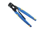
1. INTRODUCTION
This instruction sheet covers the use of Hand
Crimping Tools 45449 and 45450 (see Figure 1)
which are designed to crimp PLASTI–GRIP parallel
splices shown in Figure 2. Read these instructions
thoroughly before using the tool.
Insert Wires in Splice as Shown Above
One Dot
NOTE: Not to Scale
Reasons for reissue are provided in Section 6,
REVISION SUMMARY.
NOTE
i
All dimensions on this document are in metric
units [with inches in brackets]. Figures and
illustrations are for identification only and are not
drawn to scale.
E
2007 Tyco Electronics Corporation, Harrisburg, PA
All International Rights Reserved
Finished Crimp
WIRE
COLOR AND
SIZE
DOT CODE
45449
22-16
Red - One Dot
45450
16-14
Blue - Two Dots
TOOL
WIRE STRIP LENGTH
MIN.
MAX.
7 87 [[.310]
7.87
310]
8 64 [.340]
8.64
[ 340]
Figure 2
TOOLING ASSISTANCE CENTER 1-800-722-1111
This controlled document is subject to change.
PRODUCT INFORMATION 1-800-522-6752
For latest revision and Regional Customer Service,
TE logo and Tyco Electronics are trademarks.
*Trademark. Other products, logos, and company names used are the property of their respective owners.
visit our website at www.tycoelectronics.com
1 of 5
LOC B
�408-1548
Hand Crimping Tools 45449 and 45450
3. CRIMPING PROCEDURE
NOTE
4. Your own established standards.
Each hand tool is coated with a preservative to
prevent rust or corrosion. Wipe this preservative
i
from the tool, particularly from the crimping jaws,
before using the tool.
Refer to the chart in Figure 2 and select wire of
desired size (within the range of the tool being used).
Strip the wire to the length indicated. Do NOT cut or
nick the wire strands.
Select the appropriate PLASTI–GRIP splice (refer to
Catalog 82042 for desired size and part number).
Refer to Figure 2 and Figure 3 and proceed as
follows:
1. Open the tool’s jaws by squeezing the handles
until the ratchet releases and then allow the
handles to open FULLY.
2. Insert stripped wires into both ends of the splice.
3. Center splice (with wires inserted) in crimper
jaws.
4. To complete crimp, close handles until ratchet
releases. Allow handles to open FULLY. Crimped
splice may be removed.
Center Splice
Between Stops
The hand tool is inspected before being shipped;
however, Tyco Electronics recommends that the tool
be inspected immediately upon its arrival at your
facility to ensure that the tool has not been damaged
during shipment. Due to the precision design, it is
important that no parts of these tools be interchanged
except those replacement parts listed in Figure 7.
4.1. Daily Maintenance
1. Remove dust, moisture, and other contaminants
with a clean brush, or a soft, lint–free cloth. Do
NOT use objects that could damage the tool.
2. Make certain that the retaining pins are in place
and that they are secured with retaining rings.
3. All pins, pivot points, and bearing surfaces
should be protected with a thin coat of any good
SAE No. 20 motor oil. Do not oil excessively.
4. When the tool is not in use, keep handles closed
to prevent objects from becoming lodged in the
crimping dies. Store the tool in a clean, dry area.
4.2. Lubrication
Lubricate all pins, pivot points, and bearing surfaces
with SAE No. 20 motor oil as follows:
Tools used in daily production – lubricate daily
Tools used daily (occasional) – lubricate weekly
Tools used weekly – lubricate monthly
Wipe excess oil from tool, particularly from crimping
area. Oil transferred from the crimping area onto
certain terminations may affect the electrical
characteristics of an application.
4.3. Periodic Inspection
1. Hand tool should be immersed (handles partially
closed) in a reliable commercial degreasing
compound to remove accumulated dirt, grease,
and foreign matter.
Stops
Figure 3
4. MAINTENANCE AND INSPECTION PROCEDURE
Tyco Electronics recommends that a maintenance
and inspection program be performed periodically to
ensure dependable and uniform terminations.
Frequency of inspection depends on:
1. The care, amount of use, and handling of the
hand tool.
2. The presence of abnormal amounts of dust and
dirt.
3. The degree of operator skill.
2 of 5
2. Close tool handles until ratchet releases and
then allow them to open freely. If they do not open
quickly and fully, the spring is defective and must
be replaced. See Section 5, REPLACEMENT AND
REPAIR.
3. Inspect head assembly for worn, cracked, or
broken dies. If damage is evident, return the tool to
Tyco Electronics for evaluation and repair. See
Section 5, REPLACEMENT AND REPAIR.
4.4. Crimping Die Closure Inspection
This inspection requires the use of plug gages
conforming to the dimensions shown in Figure 4. Tyco
Electronics does not manufacture or market these
gages.
Tyco Electronics Corporation
Rev C
�408-1548
Hand Crimping Tools 45449 and 45450
Suggested Plug Gage Design
Barrel Crimp
GO Dim.
NO-GO Dim.
A"
A"
45449
45450
B"
F"
C"
TOOL
NUMBER
NO-GO Dim.
B"
F"
C"
25.4
E"
Insulation Crimp
GO Dim.
A"
[1.00]
Dim.
Min.
BARREL CRIMP
DIMENSIONS{ A"
GO
C"
25.4
E"
E"
B"
[1.00]
Dim.
Min.
INSULATION CRIMP
DIMENSIONS{ B"
F"
NO-GO
GO
C"
E"
F"
NO-GO
2.77
2.92
3.18
8.00
2.16
2.59
3.10
3.18
8.00
2.16
[.109]
[.115]
[.125]
[.315]
[.085]
[.102]
[.122]
[.125]
[.315]
[.085]
3.02
3.18
3.18
9.53
2.74
2.84
3.35
3.18
9.53
2.74
[.119]
[.125]
[.125]
[.375]
[.108]
[.112]
[.132]
[.125]
[.375]
[.108]
{Plug gage dimensions apply when tool is bottomed, but not under pressure.
Figure 4
To gage die closure, refer to Figure 5 and Figure 6
and proceed as follows:
1. Remove traces of oil or dirt from the crimping
chambers and plug gage.
2. Open tool crimping jaws and insert the GO
element of the proper wire barrel plug gage into the
space between the wire barrel die (inner) and the
insulation die (outer). Plug gage may be inserted
from either side of the tool.
Insert End of Gage Into
Space Between Insulation
Barrel Die and Wire Barrel
Die
3. Close the tool handles until it is evident that the
jaws have bottomed; then hold in this position. Do
NOT force the jaws beyond initial contact.
4. Align the GO element with the wire barrel
crimping chamber. Push element straight into the
crimping chamber without using force. The GO
element must pass completely through the
crimping chamber.
5. Check the wire barrel crimping chamber with the
NO GO element in the same manner as steps 2
through 4. The NO GO element may start entry,
but must not pass completely through the crimping
chamber.
6. Check both sets of insulation barrel crimping
dies with the proper insulation barrel plug gage
the same manner as steps 2 through 5.
If both wire barrel and insulation barrel crimping dies
conform to the gage inspection, the crimping
chambers are considered dimensionally correct. If
correct, the tool should be lubricated with a thin coat
of any good SAE No. 20 motor oil and returned to
service. If not correct, the tool must be returned to
Tyco Electronics for further evaluation and repair.
Refer to Section 5, REPLACEMENT AND REPAIR.
Insulation
Wire Barrel
Barrel Die
Die
Figure 5
Rev
C
in
For additional information regarding the use of a plug
gage, refer to Instruction Sheet 408–7424.
Tyco Electronics Corporation
3 of 5
�408-1548
Hand Crimping Tools 45449 and 45450
Tool
Gage May be Inserted
Crimping Jaws
in Either Side of Tool
Bottomed
When Gaging Wire
Barrel Die
Plug Gage
Inspection of Wire Barrel
Crimping Dies with Plug Gage
Inspection of Insulation Barrel
Crimping Dies with Plug Gage
Wire Barrel
Insulation Barrel
Die
Die
GO" Gage Must Pass Completely
Through the Crimping Surface
Insulation Barrel
Wire Barrel
Die
Die
NO-GO" Gage May Enter Partially, but
Must Not Pass Completely Through the
Length of the Crimping Surface
Figure 6
4.5. CERTI-CRIMP Ratchet Inspection
The CERTI–CRIMP ratchet feature on hand tools
should be checked to ensure that the ratchet does not
release prematurely, allowing the crimping dies to
open before they have fully bottomed. Obtain a
0.025–mm [.001–in.] shim that is suitable for checking
the clearance between the bottoming surfaces of the
crimping dies. Proceed as follows:
1. Select the maximum size wires and strip them
according to dimensions listed in Figure 2.
2. Select splice corresponding to the selected wire
size (refer to Figure 2).
4 of 5
3. Position the splice and wires between the
crimping dies, as described in Section 3,
CRIMPING PROCEDURE.
4. Hold the splice and wires in place and squeeze
the handles until the CERTI–CRIMP ratchet
releases. Hold the handles in this position,
maintaining just enough tension to keep the dies
closed.
5. Check the clearance between the bottoming
surfaces of the crimping dies. If the clearance is
0.025 mm [.001 in.] or less, the ratchet is
satisfactory. If clearance exceeds 0.025 mm
[.001 in.], the ratchet is out of adjustment and must
be repaired. See Section 5, REPLACEMENT AND
REPAIR.
Tyco Electronics Corporation
Rev
C
�408-1548
Hand Crimping Tools 45449 and 45450
2
3
1
95.3
[3.75]
(Closed)
279
[11.00]
WEIGHT: Approx. 526 g [1 lb. 3 oz.]
19.1 [.75]
ITEM
PART NUMBER
DESCRIPTION
1
21045-3
RING, Retaining
1
2
21045-6
RING, Retaining
1
3
39364
SPRING
1
69–65
Figure 7
5. REPLACEMENT AND REPAIR
Replacement parts are listed in Figure 7. Parts other
than those listed in Figure 7 should be replaced to
ensure quality and reliability of the tool. Order
replacement parts through your Tyco Electronics
Representative, or call 1–800–526–5142, or send a
facsimile of your purchase order to 1–717–986–7605,
or write to:
CUSTOMER SERVICE (38–35)
TYCO ELECTRONICS CORPORATION
P.O. BOX 3608
HARRISBURG, PA 17105–3608
Rev
C
QTY
6. REVISION SUMMARY
This is a summary of changes and additions made to
this instruction sheet:
S Updated document to corporate requirements
S New format
Tyco Electronics Corporation
5 of 5
�


 工商网监
湘ICP备2023018690号
工商网监
湘ICP备2023018690号
