Bulletin I2068 rev. C 04/00
SD603C..C SERIES
FAST RECOVERY DIODES Features
High power FAST recovery diode series 1.0 to 2.0 µs recovery time High voltage ratings up to 2200V High current capability Optimized turn on and turn off characteristics Low forward recovery Fast and soft reverse recovery Press-puk encapsulation Case style conform to JEDEC B-43 Maximum junction temperature 125°C
Hockey Puk Version
600A
Typical Applications
Snubber diode for GTO High voltage free-wheeling diode Fast recovery rectifier applications
case style B-43
Major Ratings and Characteristics
Parameters
IF(AV) @ T hs IF(RMS) @ T hs IFSM @ 50Hz @ 60Hz It
2
SD603C..C
600 55 942 25 8320 8715 346 316 400 to 2200 1.0 to 2.0
Units
A °C A °C A A KA2s KA2s V µs °C °C
@ 50Hz @ 60Hz
VRRM range trr range @ TJ TJ
25 - 40 to 125
www.irf.com
1
�S D603C..C Series
Bulletin I2068 rev. C 04/00
ELECTRICAL SPECIFICATIONS Voltage Ratings
Type number Voltage Code
04 SD603C..S10C 08 10 12 SD603C..S15C 14 16 20 SD603C..S20C 22
V RRM max. repetitive peak and off-state voltage V
400 800 1000 1200 1400 1600 2000 2200
VRSM , maximum nonrepetitive peak voltage V
500 900 1100 1300 1500 1700 2100 2300
I RRM max. TJ = 125°C mA
45
Forward Conduction
Parameter
IF(AV) Max. average forward current @ Heatsink temperature IF(RMS) Max. RMS current IFSM Max. peak, one-cycle non-repetitive forward current
SD603C..C
600(300) 55(75) 942 8320 8715 7000 7330
Units
A °C A
Conditions
180 ° conduction, half sine wave. Double side (single side) cooled @ 25°C heatsink temperature double side cooled t = 10ms t = 8.3ms No voltage reapplied 100% VRRM reapplied No voltage reapplied 100% VRRM reapplied Sinusoidal half wave, Initial TJ = TJ max.
A
t = 10ms t = 8.3ms t = 10ms
I2 t
Maximum I t for fusing
2
346 316 245 224 KA2s
t = 8.3ms t = 10ms t = 8.3ms
I2 √ t
Maximum I2√t for fusing
3460 1.36 1.81 0.87 0.67 2.97
KA2√ s V mΩ V
t = 0.1 to 10ms, no voltage reapplied (16.7% x π x IF(AV) < I < π x IF(AV)), TJ = TJ max. (I > π x IF(AV)), TJ = TJ max. (16.7% x π x IF(AV) < I < π x IF(AV)), TJ = TJ max. (I > π x IF(AV)), TJ = TJ max. Ipk= 1885A, T J = 25°C, tp = 10ms sinusoidal wave
V F(TO)1 Low level of threshold voltage V F(TO)2 High level of threshold voltage r f1 r f2 VFM Low level of forward slope resistance High level of forward slope resistance Max. forward voltage
Recovery Characteristics
Code
TJ = 25 oC typical t (µs)
rr
Test conditions
I
pk
Max. values @ TJ = 125 °C
V
r
di/dt (A/µs)
t
rr
Q
rr
I
rr
@ 25% I RRM Square Pulse (A) (V)
@ 25% IRRM ( µs) 2.0 (µC) 45 87 97 (A) 34 51 55
S10 S15 S20
1.0 1.5 2.0 1000 25 -30
3.2 3.5
2
www.irf.com
�S D603C..C Series
Bulletin I2068 rev. C 04/00
Thermal and Mechanical Specifications
Parameter
TJ Tstg Max. operating temperature range Max. storage temperature range
SD603C..C
-40 to 125 -40 to 150 0.076 0.038 9800 (1000) 83 B-43
Units
°C
Conditions
RthJ-hs Max. thermal resistance, junction to heatsink F wt Mounting force, ± 10% Approximate weight Case style
K/W N (Kg) g
DC operation single side cooled DC operation double side cooled
See Outline Table
∆RthJ-hs Conduction
(The following table shows the increment of thermal resistence RthJ-hs when devices operate at different conduction angles than DC)
Conduction angle
180° 120° 90° 60° 30°
Sinusoidal conduction
Single Side Double Side 0.006 0.008 0.010 0.015 0.026 0.007 0.008 0.010 0.015 0.025
Rectangular conduction
Single Side Double Side 0.005 0.008 0.011 0.016 0.026 0.005 0.008 0.011 0.015 0.025
Units
Conditions
K/W
TJ = TJ max.
Ordering Information Table
Device Code
SD
1 1 2 3 4 5 6 7 Diode Essential part number 3 = Fast recovery C = Ceramic Puk
60
2
3
3
C
4
22 S20
5 6
C
7
Voltage code: Code x 100 = V RRM ( see Voltage Ratings table) t rr code (see Recovery Characteristics table) C = Puk Case B-43
www.irf.com
3
�S D603C..C Series
Bulletin I2068 rev. C 04/00
Outline Table
3.5 (0.14) DIA. NOM. x 1.8 (0.07) DEEP MIN. BOTH ENDS
0.8(0.03) MIN. BOTH ENDS
25.3 (1) DIA. MAX. TWO PLACES
14.4 ( 0.57)
15.4 ( 0.61)
4 2 (1 .65 ) D IA. M A X .
Conform to JEDEC B-43
All dimensions in millimeters (inches) Quote between upper and lower pole pieces has to be considered after application of Mounting Force (see Thermal and Mechanical Specification)
40.5 (1.59) DIA. MAX.
Maximum Allowable Heatsink Temperature (°C)
M a xim u m A llo w a b le H e a tsin k Te m p e ra t ure (° C )
130 120 110 100 90 80
SD 6 0 3 C ..C S e rie s (Sin g le S id e C o o le d ) R th J-hs (D C ) = 0 .0 7 6 K / W
130 120 110 100 90 80 70 60 0 100 200 300 30° 60° 90° 120° 180° DC 400 500 SD 603C..C Series (Single Side Cooled) R thJ-h s (DC) = 0.076 K/W
Co n duc tio n A ng le
C o nd uc tio n Pe rio d
3 0° 70 0 50 1 00 1 50
6 0°
9 0° 120 ° 25 0
18 0° 3 00 3 50
200
A v e r a g e F o rw a rd C u rre n t (A )
Fig. 1 - Current Ratings Characteristics
Averag e Forw ard Current (A)
Fig. 2 - Current Ratings Characteristics
4
www.irf.com
�S D603C..C Series
Bulletin I2068 rev. C 04/00
Maxim um Allowable Heatsin k Tem perature ( °C) M a x im u m A llo w a b le H e a t sin k Te m p e ra t u re ( ° C ) 130 120 110 100
C o nd uc tio n A ng le
SD603C..C Series (Double Side Cooled) R th J- hs (DC) = 0.038 K/W
13 0 12 0 11 0 10 0 90 80 70 60 50 DC 40 0 200 40 0 60 0 8 00 1 0 00 A v e ra g e Fo rw a rd C u rre n t (A )
Fig. 4 - Current Ratings Characteristics
Co nd uc tio n Pe rio d
SD 6 0 3 C ..C S e r ie s (D o u b le Sid e C o o le d ) R th J-hs (D C ) = 0 .0 3 8 K / W
90 80 70 60 50 0 100 200 300 400 500 600 700 Average Forward Curren t (A)
Fig. 3 - Current Ratings Characteristics
30° 60°
90° 120° 180 °
30 °
60° 90°
120°
180°
Maxim um Average Forward Pow er Loss (W)
Maxim um Average Forward Power Loss (W)
1800 1600 1400 1200 1000 800 600 400 200 0 0 100 200 300 400 500 600 Average Forw ard C urren t (A)
Fig. 5 - Forward Power Loss Characteristics
Co n duc tio n An gle
2500 DC 180° 120° 90° 60° 30°
180 ° 120 ° 90° 60° 30° RMS Lim it
2000
1500
1000
RMS Lim it
C o ndu ctio n P e rio d
SD603C..C Series TJ = 125°C
500
SD603C..C Series TJ = 125°C 0 200 400 600 800 1000
0 Averag e Forw ard Current (A)
Fig. 6 - Forward Power Loss Characteristics
P e ak H a lf Sin e W a v e Fo rw a rd C u rr e n t (A )
P e a k H a lf Sin e W av e Fo rw ard C u rre n t (A )
8 0 00 7 5 00 7 0 00 6 5 00 6 0 00 5 5 00 5 0 00 4 5 00 4 0 00 3 5 00 3 0 00 2 5 00 1
A t A n y R a te d Lo a d C o n d itio n a n d W it h R a t e d V RRM A p p lie d F o llo w in g S u rg e . In it ia l TJ = 1 2 5 ° C @ 6 0 H z 0 .0 0 8 3 s @ 5 0 H z 0 .0 1 0 0 s
9000 8000 7000 6000 5000 4000 3000
M a x im u m N o n Re p e t itiv e S u rg e C u rre n t V e rsu s P u lse Tra in D u ra t io n . In itia l TJ = 1 2 5 ° C N o V o lta g e R e a p p lie d R a t e d V RR M R e a p p lie d
SD 6 0 3 C ..C S e rie s
S D 6 0 3 C ..C S e rie s
10
100
2000 0.01
0.1 Pu lse T ra in D u ra tio n (s)
1
Num ber o f Eq ual Am plitude Ha lf C yc le Cu rre nt Pu lses ( N)
Fig. 7 - Maximum Non-repetitive Surge Current Single and Double Side Cooled
Fig. 8 - Maximum Non-repetitive Surge Current Single and Double Side Cooled
www.irf.com
5
�S D603C..C Series
Bulletin I2068 rev. C 04/00
T ra n sie n t T h e rm a l Im p e d a n c e Z thJ-hs (K / W )
1 0 00 0 In sta nta n e o us Fo rw ard C urre nt ( A )
0 .1 S D 6 0 3 C ..C Se rie s
1 0 00
TJ = 2 5 ° C 100 TJ = 1 2 5 ° C
0 .0 1 St e a d y St a te V a lu e : R th J- hs = 0 .0 7 6 K / W (Sin g le S id e C o o le d ) R th J-hs = 0 .0 3 8 K / W (D o ub le Sid e C o o le d ) (D C O p e ra t io n ) 0 .0 1 0 .1 1 10 10 0
SD 6 0 3C ..C S e rie s
10 .5 1 .5 2 .5 3 .5 4 .5 5 .5 6 .5 7 .5 8 .5 In st an ta n e o u s Fo rw ard V o lta ge ( V )
0 .0 0 1 0 .0 0 1
Sq u a re W a v e P u lse D ura t io n (s)
Fig. 10 - Thermal Impedance ZthJ-hs Characteristic
Fig. 9 - Forward Voltage Drop Characteristics
1 00
V
FP
80 Fo rw a rd R e c o v e ry ( V )
I
T = 1 2 5 °C
J
60
40
T J = 2 5 °C
20 SD 6 0 3 C ..S2 0 C Se rie s 0 0 2 00 4 00 60 0 800 1 00 0 120 0 1 40 0 16 0 0 18 00 200 0 R a te O ff R ise O f Fo rw ar d C urre n t d i/ d t ( A / use c )
Fig. 11 - Typical Forward Recovery Characteristics
M a x im um R e v e rse R e c o v e ry C h a rg e - Q rr (µ C ) M aximum Reverse Recovery Current - Ir r (A) 2 .2 2 .1 2 SD6 03C..S10C Series T J = 1 25 °C; V r = 30 V
I FM = 1 00 0 A Squa re Pu lse
M aximum Reverse Recovery Time - T rr (µs)
130 120 110 100 90 80 70 60 50 40 30 20 10 20 30 40 50 6 0 7 0 8 0 9 0 100 S D 6 0 3 C ..S1 0 C S e rie s TJ = 125 ° C; V r = 30V
2 50 A 5 00 A I FM = 1 000 A Squ are Pulse
1 20 1 10 1 00 90 80 70 60 50 40 30 20 10 10 20 30 40 5 0 60 70 80 9 0 10 0 SD 603C..S1 0C Ser ies TJ = 1 25 °C; V r = 30 V
I FM = 10 00 A Squa re P ulse 50 0 A 250 A
1 .9 1 .8 1 .7 1 .6 10
5 00 A
25 0 A
10 0
Rate O f Fall O f Fo rwa rd Cu rren t - di/dt (A /µs)
Rate O f Fall O f Fo rw ard C urre nt - di/d t (A/µs)
R ate O f Fall O f Fo rward Curre nt - di/dt (A /µs)
Fig. 12 - Recovery Time Characteristics
Fig. 13 - Recovery Charge Characteristics
Fig. 14 - Recovery Current Characteristics
6
www.irf.com
�S D603C..C Series
Bulletin I2068 rev. C 04/00
M a x im u m R e v e rse R e c o v e ry C h a rg e - Q rr ( µ C ) M ax im u m R e v e rse R e c o v e ry C u rre n t - Irr ( A ) Maxim um Reverse Recovery Time - Trr (µs) 4 SD6 03C..S15C Series T J = 1 25 °C; V r = 30V 3 .5
I FM = 1 00 0 A Sq uare Pu lse
200 180 160 140
50 0 A I FM = 1 00 0 A Squa re Pulse
1 40 1 30 1 20 1 10 1 00 90 80 70 60 50 40 30 20 10 20 30 40 5 0 60 70 80 90 100 SD 6 0 3 C ..S 1 5 C Se rie s T J= 1 2 5 °C ; V r = 3 0 V
250 A 5 00 A I FM = 1 00 0 A Squ are Pu lse
3
120 100 80 60 40 1 0 20 3 0 40 50 60 7 0 80 90 100 SD 6 0 3C ..S 1 5 C Se rie s TJ = 12 5 ° C ; V r = 30V
2 50 A
5 00 A
2 .5
25 0 A
2 10 100
Ra te O f Fa ll O f Fo rw a rd Cu rre nt - di/d t (A /µs)
R ate O f Fall O f Fo rw ard C urre nt - di/dt (A /µs)
Rate O f Fa ll O f Fo rw ard Current - d i/dt (A /µs)
Fig. 15 - Recovery Time Characteristics
4 .5 S D 6 0 3 C ..S 2 0 C Se rie s T J= 1 2 5 °C ; V r = 3 0 V 4
Fig. 16 - Recovery Charge Characteristics
M a xim u m R e v e rse R e c o v e ry C h a rg e - Q rr ( µC ) 200 180 160 140 120 100
250 A 5 00 A I FM = 1 000 A Squ are Pulse
Fig. 17 - Recovery Current Characteristics
M aximum Reverse Recov ery Current - Irr (A) 1 50 1 40 1 30 1 20 1 10 1 00 90 80 70 60 50 40 30 20 10 20 30 40 5 0 60 70 80 9 0 10 0 SD6 03C..S2 0C Series T J = 1 25 °C; V r = 30V
250 A 5 00 A I FM = 1 000 A Sq uare Pulse
M a xim u m R e v e rse Re c o v e ry Tim e - Trr ( µ s)
3 .5
I FM = 1 00 0 A Squa re Pulse
3
50 0 A
80 60 40 10 20 30 40 50 60 70 80 90 100 S D 6 0 3 C ..S2 0 C Se rie s T J = 1 2 5 °C ; V r = 3 0 V
2 .5
2 50 A
2 10 100
Ra te O f Fa ll O f Forw ard C urre nt - di/dt (A /µs)
Rate O f Fall O f Forwa rd C urre nt - di/d t (A/µs)
R ate O f Fall O f Fo rward Curre nt - di/dt (A /µs)
Fig. 18 - Recovery Time Characteristics
Fig. 19 - Recovery Charge Characteristics
Fig. 20 - Recovery Current Characteristics
1 E4
10 4 2 0 jo ule s pe r pulse 10 4 1 0. 4 0.2 0. 1 2 20 jo ule s per p ulse
P e a k Fo rw a rd C u rre n t (A )
1
2
1 E3
0.1 0. 04 0 .02 0.0 1
0.4 0.2
1 E2
tp
S D 6 0 3 C..S10 C Se ries S in uso id al Pul se T J = 1 2 5 ° C, V RRM = 11 20 V d v/ d t = 10 0 0 V/ µ s
tp
S D 6 0 3 C..S1 0 C Se rie s Trap ezo ida l Pul se T J = 1 2 5 ° C , VR R M = 1 1 2 0 V d v/ dt = 10 0 0 V/ µ s; di/ dt=5 0A / µs
1 E1 1 E1
1E 2
1E3
1 E14E 41 E11E 1
1 E2
1 E3
1 E4
Pu lse Ba se w id t h (µ s)
P ulse Ba se w id t h (µs)
Fig. 21 - Maximum Total Energy Loss Per Pulse Characteristics
www.irf.com
7
�S D603C..C Series
Bulletin I2068 rev. C 04/00
1E 4
2 0 jo ule s p er pulse 10 2 0 jo ules pe r pulse 10 4 2 1 0.4 0.2 4
P e a k Fo rw ard C u rre n t (A )
2 1
1E 3
0 .1 0. 04
0.4 0. 2
1E 2
0.0 2
S D6 0 3 C..S1 5 C Se ries S inu soi dal Pu lse T J = 1 2 5 ° C, V RRM = 1 7 6 0 V d v / dt = 1 0 0 0 V/ µs S D 6 0 3C ..S15 C Se ries Tra pezo id al Pu lse T J = 1 2 5 ° C , V RRM = 1 7 6 0V d v /dt = 1 0 00 V /µ s; di/ dt=5 0 A / µs
tp
tp
1E 1 1E1
1 E2
1 E3
1 E14E 41 E11 1 E
1 E2
1 E3
1 E4
P u lse B ase w id t h (µ s)
P u lse B a se w id t h (µ s)
Fig. 22 - Maximum Total Energy Loss Per Pulse Characteristics
1E 4
2 0 jo ules pe r p ulse 10 10 4 2 1 0 .4 20 jo ules pe r pulse
Pe a k Fo rw a rd C urr e n t ( A )
4
1E 3
2 1 0 .4 0 .2
1E 2
0.1 0. 04
S D 6 03 C..S2 0 C Se ri es S in u so id al Pu lse TJ = 1 2 5 ° C , VRRM = 1 7 60 V d v / dt = 1 0 0 0 V/ µs S D 6 03 C ..S20 C Seri es Trap ez o idal Pu lse T J = 1 2 5 ° C , V RRM = 1 7 6 0 V d v /dt = 10 0 0 V/ µ s; di/ dt= 50 A / µs
tp
tp
1E 1 1 E1
1E2
1E3
1 E14E 4 E 1 1 1 1E
1E2
1E3
1E4
P ulse Ba se w id t h ( µ s)
P u lse B a se w id t h ( µ s)
Fig. 23 - Maximum Total Energy Loss Per Pulse Characteristics
8
www.irf.com
�
很抱歉,暂时无法提供与“SD603C22S20C”相匹配的价格&库存,您可以联系我们找货
免费人工找货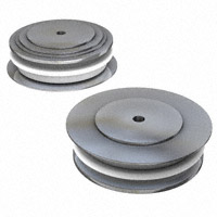


 工商网监
湘ICP备2023018690号
工商网监
湘ICP备2023018690号
