SFH615A-1, SFH615A-2, SFH615A-3, SFH615A-4
LOW INPUT CURRENT PHOTOTRANSISTOR OPTICALLY COUPLED ISOLATORS
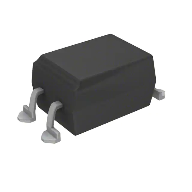
APPROVALS l UL recognised, File No. E91231 DESCRIPTION The SFH615A series of optically coupled isolators consist of infrared light emitting diodes and NPN silicon photo transistors in space efficient dual in line plastic packages. FEATURES l Options :10mm lead spread - add G after part no. Surface mount - add SM after part no. Tape&reel - add SMT&R after part no. l Low input current 1mA IF l High Current Transfer Ratios (40-320% at 10mA, 13% min at 1mA) l High Isolation Voltage (5.3kVRMS ,7.5kVPK ) l High BVCEO (70V min) l All electrical parameters 100% tested l Custom electrical selections available APPLICATIONS l Computer terminals l Industrial systems controllers l Measuring instruments l Signal transmission between systems of different potentials and impedances
2.54 7.0 6.0 1.2 5.08 4.08 1 2
Dimensions in mm
4 3
7.62 4.0 3.0 0.5 13° Max 0.26
3.0 0.5 3.35
ABSOLUTE MAXIMUM RATINGS (25°C unless otherwise specified) Storage Temperature -55°C to + 125°C Operating Temperature -55°C to + 100°C Lead Soldering Temperature (1/16 inch (1.6mm) from case for 10 secs) 260°C INPUT DIODE Forward Current Reverse Voltage Power Dissipation OUTPUT TRANSISTOR Collector-emitter Voltage BVCEO Emitter-collector Voltage BVECO Power Dissipation 70V 6V 150mW 50mA 6V 70mW
OPTION SM
SURFACE MOUNT
OPTION G
7.62
POWER DISSIPATION Total Power Dissipation 200mW
0.6 0.1 10.46 9.86
(derate linearly 2.67mW/°C above 25°C) 1.25 0.75 0.26 10.16
ISOCOMCOMPONENTSLTD Unit 25B, Park View Road West, Park View Industrial Estate, Brenda Road Hartlepool, Cleveland, TS25 1YD Tel: (01429) 863609 Fax :(01429) 863581
7/12/00
DB92538m-AAS/A1
�ELECTRICAL CHARACTERISTICS ( TA = 25°C Unless otherwise noted ) PARAMETER Input Forward Voltage (VF) Reverse Voltage (VR) Reverse Current (IR) MIN TYP MAX UNITS 1.65 6 10 V V µA V V 50 100 nA nA TEST CONDITION IF = 50mA I R = 1 0 µA VR = 6 V IC = 1mA IE = 100µA VCE = 10V
Output
Collector-emitter Breakdown (BVCEO) 70 ( Note 2 ) Emitter-collector Breakdown (BVECO) 6 Collector-emitter Dark Current (ICEO) SFH615A-1,2 SFH615A-3,4 Current Transfer Ratio (CTR) (Note 2) SFH615A-1 SFH615A-2 SFH615A-3 SFH615A-4 SFH615A-1 SFH615A-2 SFH615A-3 SFH615A-4 Collector-emitter Saturation Voltage VCESAT Input to Output Isolation Voltage VISO Input-output Isolation Resistance RISO 5300 7500 5x10¹⁰
Coupled
40 63 100 160 13 22 34 56
80 125 200 320
% % % % % % % % V VRMS VPK Ω
10mA IF , 5V VCE
1mA IF , 5V VCE
0.4
10mA IF , 2.5mA IC See note 1 See note 1 VIO = 500V (note 1)
Note 1 Note 2
Measured with input leads shorted together and output leads shorted together. Special Selections are available on request. Please consult the factory.
SWITCHING CHARACTERISTICS
1. Linear Operation (without saturation) Fig 1.
IF = 10mA, VCC = 5V, RL = 75Ω ton Turn-on Time tr Rise Time toff Turn-off Time tf Fall Time Cut-off Frequency FCO
2. Switching Operation (with saturation) Fig 2
VCC = 5V, RL = 1kΩ GROUP Turn-on Time ton tr Rise Time Turn-off Time toff tf Fall Time VCESAT
INPUT
UNITS 3.0 2.0 2.3 2.0 250 µs µs µs µs kHz
-1 -4 -2 and -3 (IF=20mA) (IF=10mA) (IF=5mA) 3.0 2.0 18 11 4.2 3.0 23 14 < 0.4 6.0 4.6 25 15
UNITS µs µs µs µs V
VCC = 5.0V R L = 75Ω OUTPUT
VCC = 5.0V R L = 1kΩ OUTPUT
ton tr OUTPUT 10% 90%
toff tf
10% 90%
FIG 1
7/12/00
FIG 2
DB92538m-AAS/A1
�Collector Power Dissipation vs. Ambient Temperature 200 Collector power dissipation P C (mW)
Collector Current vs. Collector-emitter Voltage ( normalised to SFH615A-3 ) 50 TA = 25°C
150
Collector current I C (mA)
40 30 20 10
50 30 20 15 10
100
50
IF = 5mA 0 -30 0 25 50 75 100 125 Ambient temperature TA ( °C ) Forward Current vs. Ambient Temperature 60 50 Current transfer ratio CTR (%) 0 0 2 4 6 8 10 Collector-emitter voltage VCE ( V ) Current Transfer Ratio vs. Forward Current 320 280 240 200 160 120 80 40 0 -30 0 25 50 75 100 125 1 2 5 10 20 50 Ambient temperature TA ( °C ) Relative Current Transfer Ratio vs. Ambient Temperature 1.5 Forward current IF (mA) Collector-emitter Saturation Voltage vs. Ambient Temperature 0.28 0.24 0.20 0.16 0.12 0.08 0.04 0 -30 0 25 50 75 100 Ambient temperature TA ( °C )
DB92538m-AAS/A1
VCE = 5V TA = 25°C SFH615A-4 SFH615A-3 SFH615A-2
Forward current I F (mA)
40 30 20 10 0
SFH615A-1
1.0
0.5
0 -30 0 25 50 75 100 Ambient temperature TA ( °C )
7/12/00
Collector-emitter saturation voltage V
Relative current transfer ratio
IF = 10mA VCE = 5V
CE(SAT)
(V)
IF = 10mA IC = 2.5mA
�
很抱歉,暂时无法提供与“SFH615A-3”相匹配的价格&库存,您可以联系我们找货
免费人工找货- 国内价格
- 1+4.2525
- 10+4.095
- 100+3.6225
- 500+3.528


 工商网监
湘ICP备2023018690号
工商网监
湘ICP备2023018690号