IT8209R
Extended PCI Arbiter and Clock Buffer
Preliminary Specification V0.3
�Copyright 2002 ITE, Inc.
This is Preliminary document release. All specifications are subject to change without notice.
The material contained in this document supersedes all previous documentation issued for the related products
included herein. Please contact ITE, Inc. for the latest document(s). All sales are subject to ITE’s Standard
Terms and Conditions, a copy of which is included in the back of this document.
ITE, IT8209R is a trademark of ITE, Inc.
All other trademarks are claimed by their respective owners.
All specifications are subject to change without notice.
Additional copies of this manual or other ITE literature may be obtained from:
ITE, Inc.
Marketing Department
8F, No. 233-1, Bao Chiao Rd., Hsin Tien,
Taipei County 231, Taiwan, R.O.C.
Phone:
Fax:
(02) 2912-6889
(02) 2910-2551, 2910-2552
ITE (USA) Inc.
Marketing Department
1235 Midas Way
Sunnyvale, CA 94086
U.S.A.
Phone:
Fax:
(408) 530-8860
(408) 530-8861
ITE (USA) Inc.
Eastern U.S.A. Sales Office
896 Summit St., #105
Round Rock, TX 78664
U.S.A.
Phone:
Fax:
(512) 388-7880
(512) 388-3108
If you have any marketing or sales questions, please contact:
Lawrence Liu, at ITE Taiwan: E-mail: lawrence.liu@ite.com.tw, Tel: 886-2-2912-6889 X6071,
Fax: 886-2-26578561
David Lin, at ITE U.S.A: E-mail: david.lin@iteusa.com, Tel: (408) 530-8860 X238,
Fax: (408) 530-8861
Don Gardenhire, at ITE Eastern USA Office: E-mail: don.gardenhire@iteusa.com
Tel: (512) 388-7880, Fax: (512) 388-3108
To find out more about ITE, visit our World Wide Web at:
http://www.ite.com.tw
http://www.iteusa.com
Or e-mail itesupport@ite.com.tw for more product information/services.
�Revision History
Revision History
Section
6
Revision
Page No.
• The MAX. value of VIL in section 6 DC Characteristics was revised to
“VCC x 0.3”.
11
• The MAX. value of VIH has been removed.
www.ite.com.tw
www.iteusa.com
1
IT8209R V0.3
�Contents
Contents
1. Features ................................................................................................................................................................ 1
2. General Description.............................................................................................................................................. 3
3. Block Diagram....................................................................................................................................................... 5
4. Pin Configuration .................................................................................................................................................. 7
5. IT8209R Pin Descriptions .................................................................................................................................... 9
6. DC Characteristics (VCC, AVCC = 3.3V±0.3V. Ta=0°C to 70°C)................................................................... 11
7. AC Characteristics.............................................................................................................................................. 13
8. Package Information .......................................................................................................................................... 15
9. Ordering Information .......................................................................................................................................... 17
Figures
Figure 2-1. Arbitration Scheme of IT8209R ............................................................................................................. 3
Figure 3-1. Extended PCI Arbiter Scheme............................................................................................................... 5
Figure 3-2. Clock Buffer Scheme.............................................................................................................................. 5
Figure 7-1. PCI Request Delay Timing .................................................................................................................. 13
Figure 7-2. PCI Grant Delay Timing ....................................................................................................................... 13
Figure 7-3. PCI Grant Separation Timing .............................................................................................................. 13
Figure 7-4. PCI Clock Acquisition Timing ..............................................................................................................14
Tables
Table 4-1. Pins Listed in Numeric Order.................................................................................................................. 7
Table 5-1. Pin Descriptions of Extended PCI Arbiter .............................................................................................. 9
Table 5-2. Pin Descriptions of Clock Buffer ............................................................................................................. 9
Table 5-3. Pin Descriptions of Power/Ground Signals............................................................................................ 9
Table 7-1. PCI Request Delay Timing Table ......................................................................................................... 13
Table 7-2. PCI Grant Delay Timing Table.............................................................................................................. 13
Table 7-3. PCI Grant SeparatioinTiming Table .....................................................................................................13
Table 7-4. PCI Clock Acquisition Timing Table .....................................................................................................14
www.ite.com.tw
www.iteusa.com
i
IT8209R V0.3
�Features
1. Features
n Extended PCI Arbiter
− Utilizes 1 set of SYSGNT# and SYSREQ# to support 3 PCI Masters
n Input PCI Clock
− Supports input clock frequency from 25MHz to 66MHz
n Clock Buffer
− Provides 4 zero delay clock sources
− Supports output clock frequency from 25MHz to 66MHz
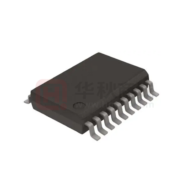
n 28-pin SSOP
www.ite.com.tw
www.iteusa.com
Specifications subject to change without notice
1
IT8209R V0.3
ITPM-PN-200205
By Peterson Lu, Mar. 7, 2002
�www.ite.com.tw
www.iteusa.com
2
IT8209R V0.3
�General Description
2. General Description
The IT8209R incorporates an extended PCI arbiter and a clock buffer.
The extended PCI arbiter utilizes one set of SYSGNT# and SYSREQ# to support 3 PCI Masters, so that two
more PCI Masters can be supported for the system. PCISTOP# input signal is useful to facilitate the fairness
arbitration. The algorithm of this arbiter uses a rotation arbitration priority that is illustrated in Figure 2-1.
The clock buffer provides 4 zero delay and low jitter clock sources. PCICLKI is the clock input of the clock buffer,
and PCICLKOUT is the clock output fed back internally to the input of the built-in PLL to reduce the clock skew.
If zero clock skew is required, PCICLKOUT and PCICLK1 to PCICLK4 must be equally loaded.
When PCICLKI input becomes inactive, the IT8209R will enter power down mode. In power down mode, all
clock outputs are low and other control outputs are deasserted.
The IT8209R is available in 28-pin SSOP package.
PCI Device 1
PCI Device 2
PCI Device n
Central PCI Arbiter
(Chipset)
PCI Device
n-1
PCI Device x
Extended
Device 3
Extended
Device 1
Extended
Device 2
Extended PCI Arbiter
(IT8209R)
Figure 2-1. Arbitration Scheme of IT8209R
www.ite.com.tw
www.iteusa.com
3
IT8209R V0.3
�www.ite.com.tw
www.iteusa.com
4
IT8209R V0.3
�Block Diagram
3. Block Diagram
PCIREQ1#
PCI Bus
SYSREQ#
PCI Master 1
PCIGNT1#
IT8209R
PCIREQ2#
PCI Master 2
PCIGNT2#
SYSGNT#
PCIREQ3#
PCI Master 3
PCIGNT3#
Figure 3-1. Extended PCI Arbiter Scheme
PCICLK1
PCI Device 1
PCICLK2
Clock
Generator
PCICLKI
IT8209R
PCI Device 2
PCICLK3
PCI Device 3
PCICLK4
PCI Device 4
PCICLKOUT
Load
Figure 3-2. Clock Buffer Scheme
www.ite.com.tw
www.iteusa.com
5
IT8209R V0.3
�www.ite.com.tw
www.iteusa.com
6
IT8209R V0.3
�Pin Configuration
4. Pin Configuration
Pin
1
2
3
4
5
6
7
8
9
10
11
12
13
14
1
2
3
4
5
6
7
8
9
10
11
12
13
14
28
27
26
25
24
23
22
21
20
IT8209R
PCIFRAME#
PCISTOP#
SYSREQ#
SYSGNT#
PCIREQ1#
VSS
PCIGNT1#
PCIREQ2#
VCC
PCIGNT2#
PCIREQ3#
PCIGNT3#
NC
NC
Signal
19
18
17
16
15
Pin
PCIFRAME#
PCISTOP#
SYSREQ#
SYSGNT#
PCIREQ1#
VSS
PCIGNT1#
PCIREQ2#
VCC
PCIGNT2#
PCIREQ3#
PCIGNT3#
NC
NC
15
16
17
18
19
20
21
22
23
24
25
26
27
28
AVCC
PCICLKI
PCIRST#
AVSS
VSS
PCICLKOUT
PCICLK1
VCC
PCICLK2
PCICLK3
PCICLK4
VSS
NC
NC
Signal
NC
NC
VSS
PCICLK4
PCICLK3
PCICLK2
VCC
PCICLK1
PCICLKOUT
VSS
AVSS
PCIRST#
PCICLKI
AVCC
Table 4-1. Pins Listed in Numeric Order
www.ite.com.tw
www.iteusa.com
7
IT8209R V0.3
�www.ite.com.tw
www.iteusa.com
8
IT8209R V0.3
�IT8209R Pin Descriptions
5. IT8209R Pin Descriptions
Table 5-1. Pin Descriptions of Extended PCI Arbiter
Signal
Pin(s) No.
Attribute
Extended PCI Arbiter Signals (3.3V CMOS I/F, 5V tolerant)
PCIFRAME#
1
PIU
PCI Bus FRAME# Signal
Description
The pin can be connected to PCI Bus FRAME# signal or not
connected to any signals.
PCISTOP#
SYSREQ#
SYSGNT#
PCIREQ1#
PCIGNT1#
PCIREQ2#
PCIGNT2#
PCIREQ3#
PCIGNT3#
PCIRST#
2
3
4
5
7
8
10
11
12
26
PIU
O12
PIU
PIU
O12
PIU
O12
PIU
O12
IK
PCI Bus STOP# Signal
PCI Bus Request
PCI Bus Grant
Request Signal from Extended PCI Master 1
Grant Signal to Extended PCI Master 1
Request Signal from Extended PCI Master 2
Grant Signal to Extended PCI Master 2
Request Signal from Extended PCI Master 3
Grant Signal to Extended PCI Master 3
PCI Bus RST# Signal
Table 5-2. Pin Descriptions of Clock Buffer
Signal
Pin(s) No.
Attribute
Clock Buffer Signals (3.3V CMOS I/F)
PCICLK4
18
O12
PCICLK3
19
O12
PCICLK2
20
O12
PCICLK1
22
O12
PCICLKOUT
23
O12
PCICLKI
27
I
Description
PCICLK Output 4
PCICLK Output 3
PCICLK Output 2
PCICLK Output 1
PCICLK Output (for internal feedback)
PCICLK Input
Table 5-3. Pin Descriptions of Power/Ground Signals
Signal
Pin(s) No.
Power Ground Signals
VSS
6, 17, 24
VCC
9, 21
AVSS
25
AVCC
28
Attribute
I
I
I
I
Description
Ground
Power Supply of 3.3V
Analog Ground for analog PLL
Analog VCC for analog PLL
Notes: IO cell types are described as below:
I: Input PAD.
IK: Schmitt Trigger Input PAD.
PIU: PCI Bus Specified Input PAD (integrated a 75K ohms pull-up resistor).
O12: 12mA Output PAD.
www.ite.com.tw
www.iteusa.com
9
IT8209R V0.3
�www.ite.com.tw
www.iteusa.com
10
IT8209R V0.3
�DC Characteristics
6. DC Characteristics (VCC, AVCC = 3.3V±0.3V. Ta=0°C to 70°C)
Absolute Maximum Ratings*
*Comments
Applied Voltage of VCC, AVCC............. -0.3V to +4.6V
Stresses above those listed under "Absolute
Maximum Ratings" may cause permanent
damage to this device. These are stress
ratings only. Functional operation of this device
at these or any other conditions above those
indicated in the operational sections of this
specification is not implied, and exposure to
absolute maximum rating conditions for
extended periods may affect device reliability.
Input Voltage of 3.3V Interface ......-0.3V to VCC+0.3V
Input Voltage of 5V tolerant Interface … -0.3V to 5.25V
Tcase ......................................................... 0°C to +70°C
Storage Temperature ......................... -40°C to +125°C
DC Electrical Characteristics (Ta = 0°C to 70°C)
Symbol
Parameter
Min.
VIL
Input Low Voltage
- 0.3V
VIH
Input High Voltage
VCC x 0.7
VOL
Output Low Voltage
VOH
Output High Voltage
IIL
Input Low Current
Typ.
Max.
Conditions
VCC x 0.3
VCC=3.0 ~ 3.6V
VCC=3.0 ~ 3.6V
0.5
2.4
IOL= -12mA
IOH= 12mA
-1µA
1µA
VIL= VSS
no pull-up or pull-down
IIH
Input High Current
-1µA
1µA
VIH= VCC
no pull-up or pull-down
IOZ
Tri-state Leakage
Current
Cin
Input Capacitance
3pF
Cout
Output Capacitance
3pF
Cbld
Bi-directional Buffer
3pF
RI
Input Pull-Up
Resistance
www.ite.com.tw
www.iteusa.com
-10µA
10µA
40KΩ
75KΩ
11
170KΩ
VIL =0V
IT8209R V0.3
�www.ite.com.tw
www.iteusa.com
12
IT8209R V0.3
�AC Characteristics
7. AC Characteristics
PCIREQn#
t1
SYSREQ#
Figure 7-1. PCI Request Delay Timing
Symbol
t1
Table 7-1. PCI Request Delay Timing Table
Parameter
Min.
Typ.
0
PCIREQn# (n=1, 2, 3) to SYSREQ# asserted
Max.
7
Unit
ns
Typ.
-
Max.
8.5
Unit
ns
Min.
Typ.
Max.
Unit
1
-
-
Clock
Period
SYSGNT#
t2
PCIGNTn#
Figure 7-2. PCI Grant Delay Timing
Symbol
t2
Table 7-2. PCI Grant Delay Timing Table
Parameter
Min.
SYSGNT# to PCIGNTn# (n=1, 2, 3) asserted
0
PCIGNTm#
t3
PCIGNTn#
Figure 7-3. PCI Grant Separation Timing
Table 7-3. PCI Grant Separation Timing Table
Symbol
t3
Parameter
PCIGNTm# (m=1, 2, 3) deasserted to PCIGNTn#
(n=1, 2, 3) asserted (n != m)
www.ite.com.tw
www.iteusa.com
13
IT8209R V0.3
�IT8209R
PCICLKI
PCICLKn
t4
Figure 7-4. PCI Clock Acquisition Timing
Table 7-4. PCI Clock Acquisition Timing Table
Symbol
Parameter
Min.
Typ.
Max.
Unit
t4
PCICLKI stable to PCICLKn (n=1, 2, 3, 4, out) stable
-
-
60
us
www.ite.com.tw
www.iteusa.com
14
IT8209R V0.3
�Package Information
8. Package Information
SSOP28L Outline Dimensions
unit: inches/mm
E
HE
15
28
L
1
b
Detail F
14
D
L1
A1
e
S
A
A2
C
D
y
Seating Plane
See Detail F
Symbol
Dimension in inches
Min
Nom
Max
Min
Nom
Max
A
0.053
0.064
0.069
1.35
1.63
1.75
A1
0.004
0.006
0.010
0.10
0.152
0.25
A2
-
-
0.059
-
-
1.50
b
0.008
0.010
0.012
0.203
0.254
0.305
C
0.007
-
0.010
0.178
-
0.250
D
0.386
0.390
0.394
9.80
9.91
10.00
E
0.150
0.154
0.157
3.80
3.91
4.00
e
www.ite.com.tw
www.iteusa.com
Dimension in mm
0.025BSC
0.635BSC
HE
0.228
0.236
0.244
5.80
5.99
6.20
L
0.016
0.025
0.050
0.40
0.635
1.27
L1
0.041REF.
1.04REF.
S
0.033REF.
0.838REF.
y
-
-
0.004
-
-
0.10
θ
0°
-
8°
0°
-
8°
15
IT8209R V0.3
�www.ite.com.tw
www.iteusa.com
16
IT8209R V0.3
�Ordering Information
9. Ordering Information
Part No.
Package
IT8209R
28 SSOP
www.ite.com.tw
www.iteusa.com
17
IT8209R V0.3
�


 工商网监
湘ICP备2023018690号
工商网监
湘ICP备2023018690号
