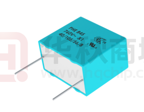
Metallized Polypropylene Film EMI Suppression Capacitors
PHE845, Class X1, 760 VAC, 105°C
Overview
Applications
The PHE845 series is constructed of metallized
polypropylene film encapsulated with self-extinguishing
resin in a box of material that meets the requirements of
UL 94 V–0.
For use as an electromagnetic interference (EMI)
suppression filter in across-the-line applications that
require X1 safety classification. Suitable for use in
situations in which capacitor failure does not pose a
danger of electric shock.
Benefits
• Approvals: ENEC, UL, cUL
• Class X1 (IEC 60384-14)
• THB Grade IA: 40°C, 93% RH, 500 hours at 760 V
URAC acc. to IEC 60384-14
• Rated voltage: 760 VAC 50/60 Hz
• Capacitance range: 0.01 – 1.0 µF
• Lead spacing: 22.5 – 37.5 mm
• Capacitance tolerance: ±20%, ±10%
• Climatic category 40/105/56/B, IEC 60068-1
• Tape & Reel in accordance with IEC 60286-2
• RoHS compliant and lead-free terminations
• Operating temperature range of −40°C to +105°C
• 100% screening factory test at 4,250 VDC
• Self-healing properties
Customer Part Number
PHE845
V
D
5100
M
R06L2
Series
Rated Voltage (VAC)
Lead Spacing (mm)
Capacitance Code (pF)
Capacitance
Tolerance
Packaging
X1, Metallized
Polypropylene
V = 760
D = 22.5
F = 27.5
R = 37.5
The last three digits
represent significant
figures. The first digit
specifies the total
number of digits.
K = ±10%
M = ±20%
See Ordering Options
Table
KEMET Internal Part Number
F
845
D
D
103
M
760
C
Capacitor
Class
Series
Lead Spacing
(mm)
Size Code
Capacitance Code (pF)
Capacitance
Tolerance
Rated Voltage
(VAC)
Packaging
D = 22.5
F = 27.5
R = 37.5
See
Dimension
Table
First two digits represent
significant figures. Third
digit specifies number of
zeros.
F = Film
X1, Metallized
Polypropylene
K = ±10%
M = ±20%
760 = 760
See Ordering
Options Table
Built Into Tomorrow
© KEMET Electronics Corporation • One East Broward Boulevard�
Fort Lauderdale, FL 33301 USA • 954-766-2800 • www.kemet.com
F3109_PHE845_X1_760 • 8/15/2023
1
�Film Capacitors – Metallized Polypropylene Film EMI Suppression Capacitors
PHE845, Class X1, 760 VAC, 105°C
Ordering Options Table
Lead
Spacing
Nominal
(mm)
Lead Length
(mm)
KEMET
Lead and
Packaging
Code
Legacy
Lead and
Packaging
Code
6 +0/-1
C
R06L2(1)
Pizza Pack
6 +0/−1
Z
R06L2(1)
Bulk (Tray)–Long Leads
30 +5/−0
ALW0L
R30L2
Tape & Reel (Standard Reel)
H0= 18.5 ±0.5
L
R17T0
Tape & Reel (Large Reel)
H0= 18.5 ±0.5
P
R17T1
6 +0/−1
C
R06L2(1)
Pizza Pack
Bulk (Tray)–Long Leads
6 +0/−1
30 +5/−0
Z
ALW0L
R06L2(1)
R30L2
Tape & Reel (Large Reel)
H0= 18.5 ±0.5
P
R17T1
6 +0/−1
C
R06L2(1)
6 +0/−1
Z
R06L2(1)
Type of Leads and Packaging
Standard Lead and Packaging
Options
Bulk (Tray)–Short Leads
Other Lead and Packaging Options
22.5
Standard Lead and Packaging
Options
Bulk (Tray)–Short Leads
27.5
37.5
Other Lead and Packaging Options
Standard Lead and Packaging
Options
Bulk (Tray)–Short Leads
Other Lead and Packaging Options
Pizza Pack
(1) Please specify Bulk (Tray) or Pizza Packaging
© KEMET Electronics Corporation • One East Broward Boulevard�
Fort Lauderdale, FL 33301 USA • 954-766-2800 • www.kemet.com
F3109_PHE845_X1_760 • 8/15/2023
2
�Film Capacitors – Metallized Polypropylene Film EMI Suppression Capacitors
PHE845, Class X1, 760 VAC, 105°C
Dimensions – Millimeters
FRONT VIEW
SIDE VIEW
L
T
H
S
0.5
LL
F
KEMET Size
Code
Legacy Size
Code
DD
DG
DM
DR
DT
DW
DY
FE
FG
FK
FS
FV
RH
RK
RM
RP
D13
D17
D15
D18
D16
D20
D19
F11
F12
F03
F15
F16
R04
R02
R03
R06
S
T
H
L
F
Nominal Tolerance Nominal Tolerance Nominal Tolerance Nominal Tolerance Nominal Tolerance
22.5
22.5
22.5
22.5
22.5
22.5
22.5
27.5
27.5
27.5
27.5
27.5
37.5
37.5
37.5
37.5
±0.4
±0.4
±0.4
±0.4
±0.4
±0.4
±0.4
±0.4
±0.4
±0.4
±0.4
±0.4
±0.5
± 0.5
±0.5
±0.5
6.5
7.0
9.0
10.5
11.0
13.5
15.5
10.5
11.5
13.5
19.0
21.0
15.0
16.5
19.0
21.0
Maximum
Maximum
Maximum
Maximum
Maximum
Maximum
Maximum
Maximum
Maximum
Maximum
Maximum
Maximum
Maximum
Maximum
Maximum
Maximum
14.5
16.5
18.5
19.0
21.5
23.0
24.5
20.5
22.5
23.0
29.0
30.0
26.0
32.0
36.0
38.0
Maximum
Maximum
Maximum
Maximum
Maximum
Maximum
Maximum
Maximum
Maximum
Maximum
Maximum
Maximum
Maximum
Maximum
Maximum
Maximum
26.0
26.0
26.0
26.0
26.0
26.0
26.0
31.5
31.5
31.5
31.5
31.5
41.0
41.0
41.0
41.0
Maximum
Maximum
Maximum
Maximum
Maximum
Maximum
Maximum
Maximum
Maximum
Maximum
Maximum
Maximum
Maximum
Maximum
Maximum
Maximum
0.8
0.8
0.8
0.8
0.8
0.8
0.8
0.8
0.8
0.8
0.8
0.8
1.0
1.0
1.0
1.0
±0.05
±0.05
±0.05
±0.05
±0.05
±0.05
±0.05
±0.05
±0.05
±0.05
±0.05
±0.05
±0.05
±0.05
±0.05
±0.05
Note: See the Ordering Options Table for lead length (LL) options.
© KEMET Electronics Corporation • One East Broward Boulevard�
Fort Lauderdale, FL 33301 USA • 954-766-2800 • www.kemet.com
F3109_PHE845_X1_760 • 8/15/2023
3
�Film Capacitors – Metallized Polypropylene Film EMI Suppression Capacitors
PHE845, Class X1, 760 VAC, 105°C
Performance Characteristics
Dielectric
Plates
Winding
Leads
Protection
Rated Voltage (VR)
Polypropylene film
Metal layer deposited by evaporation under vacuum
Non-inductive type. Triple design.
Tinned wire
Plastic case, thermosetting resin-filled. Box material is solvent-resistant and flame-retardant according to UL94 V–0.
760 VAC 50/60 Hz
Capacitance Range
0.010 – 1.0 µF
Capacitance Values
E6 series (IEC 60063)
Capacitance Tolerance
Temperature Range
Climatic Category
Approvals
Related Documents
±20% standard, ±10% option
-40°C to 105°C
40/105/56/B IEC 60068-1
ENEC, UL, cUL
EN/IEC 60384-14:2005, UL 60384-14, CAN/CSA E60384-14:09
Maximum Values at +23°C
Dissipation Factor (tanδ)
Frequency
C ≤ 0.1 μF
0.1 µF < C ≤ 1 µF
1 kHz
0.1%
0.1%
10 kHz
0.2%
0.4%
100 kHz
0.6%
-
Test Voltage Between
Terminals
The 100% screening factory test is carried out at 4,250 VDC. The voltage level is selected to meet the
requirements in applicable equipment standards. All electrical characteristics are checked after the test. It is not
permitted to repeat this test as there is a risk to damage the capacitor. KEMET is not liable in such case for any
failures.
Resonance Frequency
Tabulated self-resonance frequencies fo (see Table 1 – Ratings & Part Number Reference)
Measured at +25°C ±5°C, according to IEC 60384-2
Insulation Resistance
In DC Applications
Minimum Values Between Terminals
C ≤ 0.33 μF
C > 0.33 μF
≥ 30,000 MΩ
≥ 10,000 MΩ • µF
Recommended voltage ≤ 1,500 VDC
© KEMET Electronics Corporation • One East Broward Boulevard�
Fort Lauderdale, FL 33301 USA • 954-766-2800 • www.kemet.com
F3109_PHE845_X1_760 • 8/15/2023
4
�Film Capacitors – Metallized Polypropylene Film EMI Suppression Capacitors
PHE845, Class X1, 760 VAC, 105°C
Environmental Test Data
Test
IEC Publication
Endurance
IEC 60384-14:2005
Vibration
IEC 60068-2-6 Test Fc
Bump
IEC 60068-2-29 Test Eb
Change of Temperature
IEC 60068-2-14 Test Na
Active Flammability
IEC 60384-14:2005
VR + 20 surge pulses at 4 kV (pulse every 5 seconds)
Passive Flammability
IEC 60384-14:2005
IEC 60384–1, IEC 60695–11–5 Needle Flame Test
Damp Heat Steady State
IEC 60068-2-78 Test Cab
THB Test
According to Grade IA
Procedure
1.25 x VR VAC 50 Hz, once every hour increase to 1,000 VAC for 0.1
second, 1,000 hours at upper rated temperature
3 directions at 2 hours each 10 – 55 Hz at 0.75 mm or 98 m/s2
No visible damage. No open or short circuit.
1,000 bumps at 390 m/s2
No visible damage. No open or short circuit.
Upper and lower rated temperature 5 cycles
No visible damage.
+40°C and 90 – 95% RH, 56 days
+40°C and 90 - 95% RH, 21 days at rated AC-voltage
Capacitance change (∆C/C): ≤ 10%
Dissipation factor change (∆tan δ): ≤ 24 * 10−3 (at 10 kHz) for C ≤ 1 µF
Dissipation factor change (∆tan δ): ≤ 15 * 10−3 (at 1 kHz) for C > 1 µF
Insulation resistance IR in seconds or time constant τ = CR
Rins: ≥ 50% of initial limit
Approvals
Certification Body
Mark
Specification
File Number
Intertek Semko AB
EN/IEC 60384-14
SE/0140–17E
UL
UL 60384 and
CAN/CSA E60384-14:09
(760 VAC)
E73869
Environmental Compliance
All KEMET EMI capacitors are RoHS compliant.
© KEMET Electronics Corporation • One East Broward Boulevard�
Fort Lauderdale, FL 33301 USA • 954-766-2800 • www.kemet.com
F3109_PHE845_X1_760 • 8/15/2023
5
�Film Capacitors – Metallized Polypropylene Film EMI Suppression Capacitors
PHE845, Class X1, 760 VAC, 105°C
Table 1 – Ratings & Part Number Reference
Capacitance
Value (µF)
Size Code
(KEMET/
Legacy)
0.010
0.015
0.022
0.033
0.047
0.068
0.10
0.15
0.22
0.10
0.15
0.22
0.33
0.47
0.47
0.47
0.68
1.0
DD/D13
DD/D13
DD/D13
DF/D17
DM/D15
DR/D18
DT/D16
DW/D20
DY/D19
FE/F11
FG/F12
FK/F03
FS/F15
FV/F16
RH/R04
RK/R02
RM/R03
RP/R06
Capacitance
Value (µF)
Size Code
(KEMET/Legacy)
Maximum
Dimensions in mm
T
H
L
Lead
Spacing (S)
fo
(MHz)
dV/dt
(V/
µs)
KEMET
Part Number
Legacy
Part Number
6.5
6.5
6.5
7.0
9.0
10.5
11.0
13.5
15.5
10.5
11.5
13.5
19.0
21.0
15.0
16.5
19.0
21.0
14.5
14.5
14.5
16.5
18.5
19.0
21.5
23.0
24.5
20.5
22.5
23.0
29.0
30.0
26.0
32.0
36.0
38.0
26.0
26.0
26.0
26.0
26.0
26.0
26.0
26.0
26.0
31.5
31.5
31.5
31.5
31.5
41.0
41.0
41.0
41.0
22.5
22.5
22.5
22.5
22.5
22.5
22.5
22.5
22.5
27.5
27.5
27.5
27.5
27.5
37.5
37.5
37.5
37.5
11
9.2
7.6
6.4
5.3
4.4
3.5
3.1
2.7
3.4
3.0
2.4
2.0
1.6
1.6
1.6
1.2
1.0
100
100
100
100
100
100
100
100
100
100
100
100
100
100
100
100
100
100
F845DD103(1)760(2)
F845DD153(1)760(2)
F845DD223(1)760(2)
F845DF333(1)760(2)
F845DM473(1)760(2)
F845DR683(1)760(2)
F845DT104(1)760(2)
F845DW154(1)760(2)
F845DY224M760(2)
F845FE104(1)760(2)
F845FG154(1)760(2)
F845FK224(1)760(2)
F845FS334(1)760(2)
F845FV474M760(2)
F845RH474M760(2)
F845RK474(1)760(2)
F845RM684(1)760(2)
F845RP105M760(2)
PHE845VD5100(1)(2)
PHE845VD5150(1)(2)
PHE845VD5220(1)(2)
PHE845VD5330(1)(2)
PHE845VD5470(1)(2)
PHE845VD5680(1)(2)
PHE845VD6100(1)(2)
PHE845VD6150(1)(2)
PHE845VY6220M(2)
PHE845VF6100(1)(2)
PHE845VF6150(1)(2)
PHE845VF6220(1)(2)
PHE845VF6330(1)(2)
PHE845VZ6470M(2)
PHE845VW6470M(2)
PHE845VR6470(1)(2)
PHE845VR6680(1)(2)
PHE845VW7100M(2)
T
(mm)
H
(mm)
L
(mm)
Lead Spacing
(S)
fo (MHz)
dV/dt
(V/µs)
KEMET
Part Number
Legacy
Part Number
(1) M = ±20%, K = ±10%.
(2) Insert ordering code for lead type and packaging. See the Ordering Options Table for available options.
© KEMET Electronics Corporation • One East Broward Boulevard�
Fort Lauderdale, FL 33301 USA • 954-766-2800 • www.kemet.com
F3109_PHE845_X1_760 • 8/15/2023
6
�Film Capacitors – Metallized Polypropylene Film EMI Suppression Capacitors
PHE845, Class X1, 760 VAC, 105°C
Soldering Process
The implementation of the RoHS directive has resulted in the selection of SnAuCu (SAC) alloys or SnCu alloys as primary solder.
This implementation has increased the liquidus temperature from 183ºC for SnPb eutectic alloys to 217 – 221ºC for the new
alloys. As a result, the heat stress to the components, even in wave soldering, has increased considerably due to higher pre-heat
and wave temperatures. Polypropylene capacitors are especially sensitive to heat (the melting point of polypropylene is 160 –
170ºC). Wave soldering can be destructive, especially for mechanically small polypropylene capacitors (with lead spacing of 5
– 15 mm), and great care must be taken during soldering. The recommended solder profiles from KEMET should be used. Consult
KEMET with any questions. In general, the wave soldering curve from IEC Publication 61760-1 Edition 2 serves as a solid guideline
for successful soldering. See Figure 1.
Reflow soldering is not recommended for through-hole film capacitors. Exposing capacitors to a soldering profile in excess of the
recommended limits may result in degradation of or permanent damage to the capacitors.
Do not place the polypropylene capacitor through an adhesive curing oven to cure resin for surface-mount components. Insert
through-hole parts after curing the surface mount parts. Consult KEMET to discuss the actual temperature profile in the oven, if
through-hole components must pass through the adhesive curing process. A maximum of two soldering cycles is recommended.
Allow time for the capacitor surface temperature to return to normal before the second soldering cycle.
Wave Soldering Recommendations
Manual Soldering Recommendations
300
Following is the recommendation for manual
soldering with a soldering iron.
2+3 seconds max
260°C
250
Second Wave
First Wave
Recommended Soldering Temperature
Temperature (°C)
200
400
Soldering Iron Bit Temperature (°C)
350
300
∆ T < 150°C
Cooling
Preheating
150
ca. 2°C/second
ca. 3.5°C/second typical
ca. 5°C/second
Tpreheat
100
Typical
250
50
200
150
0
100
0
40
80
120
160
200
240
Time (seconds)
50
0
0
1
2
3
4
5
6
7
8
Soldering Time (seconds)
Soldering iron tip temperature should be set
at 350°C (+10°C maximum), with the soldering
duration not to exceed 3 seconds.
© KEMET Electronics Corporation • One East Broward Boulevard�
Fort Lauderdale, FL 33301 USA • 954-766-2800 • www.kemet.com
F3109_PHE845_X1_760 • 8/15/2023
7
�Film Capacitors – Metallized Polypropylene Film EMI Suppression Capacitors
PHE845, Class X1, 760 VAC, 105°C
Soldering Process cont.
Wave Soldering Recommendations cont.
1. The table indicates the maximum set-up temperature of the soldering process.
Figure 1
Dielectric
film
material
Maximum Preheat
Temperature
Maximum Peak Soldering
Temperature
Capacitor
Capacitor
Capacitor
Capacitor
Pitch ≥ 10 mm Pitch > 15 mm Pitch ≤ 15 mm Pitch > 15 mm
Polyester
130°C
130°C
270°C
270°C
Polypropylene
110°C
130°C
260°C
270°C
Paper
130°C
140°C
270°C
270°C
Polyphenylene
Sulphide
150°C
160°C
270°C
270°C
2. The maximum temperature measured inside the capacitor: set the temperature so that the maximum temperature is
below the limit inside the element.
Dielectric Film Material
Maximum Temperature
Measured Inside the Element
Polyester
160°C
Polypropylene
110°C
Paper
160°C
Polyphenylene Sulphide
160°C
Temperature monitored inside the capacitor.
Selective Soldering Recommendations
Selective dip soldering is a variation of reflow soldering. In this method, the printed circuit board with through-hole
components to be soldered is preheated and transported over the solder bath, as in normal flow soldering, without touching
the solder. When the board is over the bath, it is stopped. Pre-designed solder pots are lifted from the bath with molten
solder only at the places of the selected components, and then pressed against the lower surface of the board to solder the
components.
The temperature profile for selective soldering is similar to the double-wave flow soldering outlined in this document.
However, instead of two baths, there is only one with a time from 3 to 10 seconds. In selective soldering, the risk of
overheating is greater than in double-wave flow soldering. Great care must be taken so that the parts do not overheat.
© KEMET Electronics Corporation • One East Broward Boulevard�
Fort Lauderdale, FL 33301 USA • 954-766-2800 • www.kemet.com
F3109_PHE845_X1_760 • 8/15/2023
8
�Film Capacitors – Metallized Polypropylene Film EMI Suppression Capacitors
PHE845, Class X1, 760 VAC, 105°C
Construction
Molded Plastic
Case
Single-sided Metallized
Polypropylene Film
(First Layer)
Detailed Cross Section
Molded Plastic Self-Extinguishing
Case
Resin
Single-sided Metallized
Polypropylene Film
(Second Layer)
Margin
FILM WINDING SCHEME OPTIONS
Single-sided Metallized Polypropylene Film
Double-sided
Margin
Metal Contact
Layer
Single-sided
Metallized
Polypropylene
Film
1 Section
Metal Contact
Layer
Margin
Single-sided
Metallized
Polypropylene
Film
Double-sided
Metallized
Polyester
Carrier
Film
Leads
2 Sections
Polyprop
Film Diel
1 Section
Winding Scheme
Single-sided
Metallized
Polypropylene
Film
Single-sided
Metallized
Polypropylene
Film
3 Sections
4 Sections
Metallized Impregnated Paper
Metallized Polyphenylene
Sulfide Film (SMR)
Metallized
Impregnated
Paper
© KEMET Electronics
1 Section
1 Section Corporation • One East Broward Boulevard�
Fort Lauderdale, FL 33301 USA • 954-766-2800 • www.kemet.com
Double-sided
Metallized
Polyester
Carrier
Film
Polypropy
Film Diele
3 Sections
Polyp
Metal Foil
Polyp
Film D
Metallized Polyphenylene Sulfide Film with
Vacuum-Evaporated
Aluminum Electrodes
F3109_PHE845_X1_760 • 8/15/2023
1 Section
9
�Film Capacitors – Metallized Polypropylene Film EMI Suppression Capacitors
PHE845, Class X1, 760 VAC, 105°C
Marking
FRONT
TOP
RIFA
Logo
Series
Rated
Voltage
Approval
Marks
IEC
Climatic
Category
Capacitance
Capacitance Manufacturing
Tolerance
Date Code
Manufacturing Date Code (IEC-60062)
Year
Code
Month
Code
2010
2011
A
January
1
B
February
2
2012
C
March
3
2013
D
April
4
2014
E
May
5
2015
F
June
6
2016
H
July
7
8
2017
J
August
2018
K
September
9
2019
L
October
O
2020
M
November
N
2021
N
December
D
2022
P
2023
R
2024
S
2025
T
2026
U
2027
V
2028
W
2029
X
2030
A
© KEMET Electronics Corporation • One East Broward Boulevard�
Fort Lauderdale, FL 33301 USA • 954-766-2800 • www.kemet.com
F3109_PHE845_X1_760 • 8/15/2023
10
�Film Capacitors – Metallized Polypropylene Film EMI Suppression Capacitors
PHE845, Class X1, 760 VAC, 105°C
Packaging Quantities
Lead
Spacing
KEMET
Legacy Thickness
Size Code Size Code
(mm)
Height
(mm)
Length
(mm)
Bulk
Short
Leads
22.5
DD
DH
DM
DT
DF
DR
DY
DW
D13
D14
D15
D16
D17
D18
D19
D20
6.5
8.0
9.0
11.0
7.0
10.5
15.5
13.5
14.5
16.0
18.5
21.5
16.5
19.0
24.5
23.0
26.0
26.0
26.0
26.0
26.0
26.0
26.0
26.0
234
186
308
253
216
264
176
209
27.5
FK
FE
FG
FM
FR
FS
FV
FH
FT
FQ
F03
F11
F12
F13
F14
F15
F16
F17
F18
F19
13.5
10.5
11.5
14.5
17.5
19.0
21.0
21.0
31.0
27.5
23.0
20.5
22.5
24.5
28.0
29.0
30.0
12.5
18.5
16.0
31.5
31.5
31.5
31.5
31.5
31.5
31.5
31.5
31.5
31.5
171
216
198
153
126
117
108
108
72
81
37.5
RK
RM
RH
RF
RP
RS
R02
R03
R04
R05
R06
R08
16.5
19.0
15.0
13.0
21.0
28.0
32.0
36.0
26.0
24.0
38.0
43.0
41.0
41.0
41.0
41.0
41.0
41.0
105
91
119
140
84
54
© KEMET Electronics Corporation • One East Broward Boulevard�
Fort Lauderdale, FL 33301 USA • 954-766-2800 • www.kemet.com
Standard
Large
Reel
Reel
ø 355 mm ø 500 mm
300
250
250
200
300
200
110
160
Ammo
Bulk
(Pizza)
600
500
500
400
600
400
250
300
440
352
308
253
396
264
176
209
250
350
300
250
171
216
198
153
126
117
108
108
72
81
105
91
119
140
84
54
F3109_PHE845_X1_760 • 8/15/2023
11
�Film Capacitors – Metallized Polypropylene Film EMI Suppression Capacitors
0
PHE845, Class X1, 760 VAC, 105°C
Lead Taping & Packaging (IEC 60286–2)
Lead Spacing 22.5 – 27.5 mm
0
rom 10 and
15 mmSpecification
to 7.5 mm
Taping
Description
Dimensions (mm)
Symbol
Lead Space
22.5
27.5
Tolerance
Lead Spacing
F
22.5
27.5
+0.6/−0.1
Carrier Tape Width
W
18
18
+1/−0.5
Hold Down Tape Width
W0
5
5
Minimum
Hole Position
W1
9
9
+0.75/−0.5
Hold Down Tape Position
W2
3
3
Maximum
Feed Hole Diameter
D0
4
4
±0.2
Feed-hole Lead Space *
P0
12.7
12.7
±0.2 **
Centering of the Lead Wire
P1
7.8
5.3
±0.7
Component Alignment
∆h
2
2
±2
Deviation Tape – Plane
∆p
1.3
1.3
Maximum
t
0.9
0.9
Maximum
H0 ***
18.5
18.5
±0.5
Tape Thickness
Height of Component
from Tape Center
*Available also 15mm
**Maximum 1 mm on 20 lead spaces
*** H0 = 16.5 mm is available upon request
© KEMET Electronics Corporation • One East Broward Boulevard�
Fort Lauderdale, FL 33301 USA • 954-766-2800 • www.kemet.com
F3109_PHE845_X1_760 • 8/15/2023
12
�Film Capacitors – Metallized Polypropylene Film EMI Suppression Capacitors
PHE845, Class X1, 760 VAC, 105°C
KEMET Electronics Corporation Sales Offices
For a complete list of our global sales offi ces, please visit www.kemet.com/sales.
Disclaimer
YAGEO Corporation and its affi liates do not recommend the use of commercial or automotive grade products for high reliability applications or manned space fl ight.
All product specifi cations, statements, information and data (collectively, the “Information”) in this datasheet are subject to change. The customer is responsible for
checking and verifying the extent to which the Information contained in this publication is applicable to an order at the time the order is placed. All Information given
herein is believed to be accurate and reliable, but it is presented without guarantee, warranty, or responsibility of any kind, expressed or implied.
Statements of suitability for certain applications are based on KEMET Electronics Corporation’s (“KEMET”) knowledge of typical operating conditions for such
applications, but are not intended to constitute – and KEMET specifi cally disclaims – any warranty concerning suitability for a specifi c customer application or use.
The Information is intended for use only by customers who have the requisite experience and capability to determine the correct products for their application. Any
technical advice inferred from this Information or otherwise provided by KEMET with reference to the use of KEMET’s products is given gratis, and KEMET assumes
no obligation or liability for the advice given or results obtained.
Although KEMET designs and manufactures its products to the most stringent quality and safety standards, given the current state of the art, isolated component
failures may still occur. Accordingly, customer applications which require a high degree of reliability or safety should employ suitable designs or other safeguards
(such as installation of protective circuitry or redundancies) in order to ensure that the failure of an electrical component does not result in a risk of personal injury
or property damage.
Although all product–related warnings, cautions and notes must be observed, the customer should not assume that all safety measures are indicated or that other
measures may not be required.
Additional information about production site flexibility can be found
KEMET is a registered trademark of KEMET Electronics Corporation.
© KEMET Electronics Corporation • One East Broward Boulevard�
Fort Lauderdale, FL 33301 USA • 954-766-2800 • www.kemet.com
F3109_PHE845_X1_760 • 8/15/2023
13
�


 工商网监
湘ICP备2023018690号
工商网监
湘ICP备2023018690号
