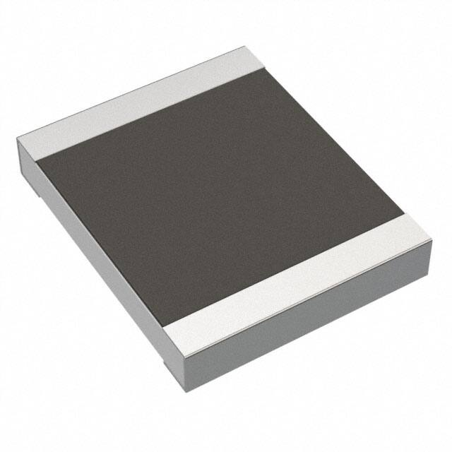
zero ohm jumper chip resistor
EU
resistors
RK73Z
features
• Silver element
• Products with lead-free terminations meet EU RoHS
requirements. EU RoHS regulation is not intended for
Pb-glass contained in electrode, resistor element and glass.
• AEC-Q200 tested: 0201(1H), 0402(1E), 0603(1J),
0805(2A), 1206(2B), 1210(2E), 2010(2H/W2H), 2512(3A/W3A)
dimensions and construction
L
c
Type
c
W
Sn
Plating
Ni
Plating
t
Protective
Coating
d
L
(Inch Size Code)
Resistive Inner
Film
Electrode
Ceramic
Substrate
Dimensions inches (mm)
W
c
d
t
1F
(01005)
.016±.0008 .008±.0008 .004±.001 .004±.001 .005±.0008
(0.4±0.02) (0.2±0.02) (0.10±0.03) (0.11±0.03) (0.13±0.02)
1H
(0201)
.024±.001 .012±.001 .004±.002 .006±.002 .009±.001
(0.6±0.03) (0.3±0.03) (0.1±0.05) (0.15±0.05) (0.23±0.03)
1E
(0402)
.039
1J
(0603)
.063±.008 .031±.004 .012±.004 .012±.004 .018±.004
(0.3±0.1) (0.45±0.1)
(1.6±0.2)
(0.8±0.1)
(0.3±0.1)
2A
(0805)
.079±.008 .049±.004 .016±.008
(2.0±0.2) (1.25±0.1) (0.4±0.2)
2B
(1206)
.063±.008
.126±.008 (1.6±0.2)
(3.2±0.2) .102±.008
(2.6±0.2)
2E
(1210)
2H
(2010)
W2H
(2010)
3A
(2512)
W3A
(2512)
(1.0
+.004
-.002
+0.1 )
-0.05
+.002
.02±.002 .008±.004 .01 -.004 .014±.002
(0.5±0.05) (0.2±0.1) (0.25 +0.05) (0.35±0.05)
-0.1
.197±.008 .098±.008
(5.0±0.2)
(2.5±0.2)
.012
(0.3
.016
(0.4
+.008
-.004
+0.2 )
-0.1
.02±.004
(0.5±0.1)
+.008
-.004
+0.2 )
-0.1
.02±.012 .026±.006 .024±.004
(0.5±0.3) (0.65±0.15) (0.6±0.1)
.016
.248±.008 .122±.008
(6.3±0.2)
(3.1±0.2)
(0.4
+.008
-.004
+0.2 )
-0.1
.026±.006
(0.65±0.15)
ordering information
RK73Z
2B
Type
Size
1F
1H
1E
1J
2A
2B
2E
W2H
W3A
2H
3A
T
Termination
Material
T: Sn
(1F, 1H, 1E, 1J, 2A, 2B,
2E, 2H/W2H, 3A/W3A)
Contact factory for
below options:
L: SnPb
(1E, 1J, 2A, 2B, 2E, 2H,
3A only)
G: Au
(1E, 1J, 2A)
TD
Packaging
TX: 01005 only: 4mm width - 1mm pitch embossed plastic
TBL: 01005 only: 2mm pitch pressed paper
TC: 0201 only: 7" 2mm pitch pressed paper
(TC: 10,000 pcs/reel, TCM: 15,000 pcs/reel)
TPL: 0402 only: 2mm pitch punch paper
TP: 0402, 0603, 0805: 7" 2mm pitch punch paper
TD: 0603, 0805, 1206, 1210:7" 4mm pitch punched paper
TE: 0805, 1206, 1210, 2010 & 2512: 7" 4mm pitch
embossed plastic
For further information on packaging, please refer to Appendix A
Specifications given herein may be changed at any time without prior notice. Please confirm technical specifications before you order and/or use.
07/15/21
KOA Speer Electronics, Inc. • 199 Bolivar Drive • Bradford, PA 16701 • USA • 814-362-5536 • Fax: 814-362-8883 • www.koaspeer.com
19
�resistors
RK73Z
zero ohm jumper chip resistor
applications and ratings
Part
Designation
Rated Ambient
Temperature
Rated
Terminal Part
Temperature
Maximum
Continuous
Current @ 70°C
—
0.5 Amps
1.0 Amp Max.
0.5 Amps
1.0 Amp Max.
1.0 Amps
2 Amp Max.
2.0 Amps
5 Amp Max.
2.0 Amps
10 Amp Max.
RK73Z1F
RK73Z1H
RK73Z1E
RK73Z1J
70°C
RK73Z2A
125°C
RK73Z2B
RK73Z2E
RK73Z2H/W2H
RK73Z3A/W3A
Maximum Overload
Current @ 70°C
(for < 1 second)
Operating
Temperature
Range
Maximum
Resistance
-55°C to +125°C
50mΩ
-55°C to +155°C
environmental applications
Derating Curve
80
80
60
1F
40
% Rated Curent
100
% Rated Curent
100
1E, 1H, 1J, 2A, 2B
2E, W2H, W3A
1H, 1E, 1J, 2A, 2B
2E, W2H, W3A
60
40
20
20
0
-60 -40
-55
-20
0
20
40
60
80
70
Ambient Temperature
(°C)
0
-60 -40
-55
100 120
140
125
155
For resistors operated at an ambient temperature of 70°C or above,
a current rating shall be derated in accordance with the above derating curve.
-20
0
20
40
60
80
Terminal Part Temperature
(°C)
100 120
140
125
155
For resistors operated at a terminal part temperature of described for
each size or above, a power rating shall be derated in accordance
with the derating curve.
Please refer to “Introduction of the derating curve based on the
terminal part temperature” in the beginning of our catalog before use.
Performance Characteristics
Parameter
Resistance
Overload (Short time)
Resistance to Solder Heat
Rapid Change of Temperature
Moisture Resistance
Endurance at 70°C
High Temperature Exposure
Requirement
Limit
Typical
50mΩ Max.
15mΩ Max.
after the test
after the test
50mΩ Max.
18mΩ Max.
after the test
after the test
50mΩ Max.
15mΩ Max.
after the test
after the test
50mΩ Max.
15mΩ Max.
after the test
after the test
100mΩ Max.
18mΩ Max.
after the test
after the test
100mΩ Max.
18mΩ Max.
after the test
after the test
100mΩ Max.
15mΩ Max.
after the test
after the test
Test Method
25°C
Maximum overload current for 5 seconds , 1 cycle
260°C ± 5°C, 10 seconds ± 1 second
-55°C (30 minutes), +125°C (30 minutes), 100 cycles
40°C ± 2°C, 90%-95% RH, 1000 hours, 1.5 hr ON, 0.5 hr OFF cycle
70°C ± 2°C, 1000 hours, 1.5 hr ON, 0.5 hr OFF cycle
+125°C, 1000 hours: 1F
+155°C, 1000 hours: 1H, 1E, 1J, 2A, 2B, 2E, W2H/2H, W3A/3A
Specifications given herein may be changed at any time without prior notice. Please confirm technical specifications before you order and/or use.
20
10/19/20
KOA Speer Electronics, Inc. • 199 Bolivar Drive • Bradford, PA 16701 • USA • 814-362-5536 • Fax: 814-362-8883 • www.koaspeer.com
�


 工商网监
湘ICP备2023018690号
工商网监
湘ICP备2023018690号
