SIDACtor ® Protection Thyristors
SLIC Protection
Fixed Voltage TwinSLIC™ Series - Modified DO-214
Description Fixed Voltage Series Modified DO-214 are unidirectional SIDACtor® devices designed to protect SLICs (Subscriber Line Interface Circuit) from damaging overvoltage transients. The series provides single port protection using fixed voltage switching devices for negative surges. All positive surges are routed through internal diodes to a ground reference. Features and Benefits Low voltage overshoot Agency Approvals
Agency Agency File Number E133083
Low on-state voltage Does not degrade with use Fails short circuit when surged in excess of ratings Applicable Global Standards TIA-968-A TIA-968-B ITU K.20/21 Enhanced Level
Integrated diodes for positive voltage surges Single-port protection
Pinout Designation
Pin 3
GR 1089 Intra-building* IEC 61000-4-5 YD/T 1082 YD/T 993 YD/T 950
Pin 1 Pin 2
ITU K.20/21 Basic Level GR 1089 Inter-building*
Schematic Symbol
* Series resistance required
1 (T) 3 (R)
2 (G)
Electrical Characteristics
VDRM @lDRM=5μA V min 58 65 75 95 120 160 VS @100V/μs V max 77 88 98 130 160 200 IH IS IT VT @IT=2.2 Amps V max 4 4 4 4 4 4 VF Capacitance V max 5 5 5 5 5 5
Part Number
Marking
Pin 1-2, 3-2 P0641CA2LRP P0721CA2LRP P0901CA2LRP P1101CA2LRP P1301CA2LRP P1701CA2LRP
mA min mA max A max 120 120 120 120 120 120 800 800 800 800 800 800 2.2 2.2 2.2 2.2 2.2 2.2
P62A P72A P92A P02A P131A P17A
See Capacitance Values table
Notes: - Absolute maximum ratings measured at TA= 25ºC (unless otherwise noted). - Devices are uni-directional
© 2011 Littelfuse, Inc. Specifications are subject to change without notice. Please refer to www.littelfuse.com for current information.
93 Revised: February 22, 2011
�SIDACtor ® Protection Thyristors
SLIC Protection
Capacitance Values
pF Pin 1-2 / 3-2 Tip-Ground, Ring-Ground MIN MAX 40 70 35 70 30 65 25 55 25 45 25 40 pF Pin 1-3 Tip-Ring MIN 20 20 20 15 15 15 MAX 45 45 40 35 30 25
Part Number P0641CA2LRP P0721CA2LRP P0901CA2LRP P1101CA2LRP P1301CA2LRP P1701CA2LRP
Note: Off-state capacitance (CO) is measured at 1 MHz with a 2 V bias.
Surge Ratings
IPP Series Series 0.2x310 1 0.5x700 2 A min 20 2x10 1 2x10 2 A min 150 8x20 1 1.2x50 2 A min 150 10x160 1 10x160 2 A min 90 10x560 1 10x560 2 A min 50 5x320 1 9x720 2 A min 75 10x360 1 10x360 2 A min 75 10x1000 1 10x1000 2 A min 45 5x310 1 10x700 2 A min 75 ITSM 50/60 Hz A min 20 A/μs max 500
di/dt
A
Notes:
1 Current waveform in μs 2 Voltage waveform in μs
- Peak pulse current rating (IPP) is repetitive and guaranteed for the life of the product. - IPP - The device must initially be in thermal equilibrium with -40°C < TJ <
Thermal Considerations
Package
Modified DO-214AA
Pin 3
Symbol TJ TS
Parameter Operating Junction Temperature Range Storage Temperature Range Thermal Resistance: Junction to Ambient
Value
Unit °C °C
Pin 1 Pin 2
R0JA
85
°C/W
V-I Characteristics
+I VF
tr x td Pulse Waveform
tr = r ise time to peak value td = decay time to half value
IPP – Peak Pulse Current – %IPP
100
Peak Value
VS VDRM -V
VT +V
Waveform = tr x td
IDRM IH IS IT -I
50
Half Value
0 0 tr td t – Time (μs)
© 2011 Littelfuse, Inc. Specifications are subject to change without notice. Please refer to www.littelfuse.com for current information.
94 Revised: February 22, 2011
�SIDACtor ® Protection Thyristors
SLIC Protection
Normalized VS Change vs. Junction Temperature
Normalized DC Holding Current vs. Case Temperature
2.0
Percent of VS Change – %
10 8 6 4 2 0 -4 -6 -8 -40 -20 0 20 40 60 80 100 120 140 160
IH (TC = 25ºC)
14 12
1.8 1.6 1.4 1.2 1.0 0.8 0.6 0.4
-40 -20 0 20 40 60 80 100 120 140 160
IH
25 °C
25°C
Ratio of
Junction Temperature (TJ) – °C
Case Temperature (TC) - ºC
Soldering Parameters
Reflow Condition
- Temperature Min (Ts(min))
Pb-Free assembly (see Fig. 1)
Figure 1
Pre Heat
- Temperature Max (Ts(max)) - Time (Min to Max) (ts)
TP
Ramp-up
tP
Critical Zone TL to TP
60-180 secs. 3°C/sec. Max. 3°C/sec. Max. 60-150 secs.
TS(max) to TL - Ramp-up Rate Reflow
- Temperature (TL) (Liquidus) - Temperature (tL)
Temperature
Average ramp up rate (Liquidus Temp (TL) to peak)
TL TS(max)
Preheat
tL
Ramp-down
TS(min)
tS
Peak Temp (TP) Time within 5°C of actual Peak Temp (tp) Ramp-down Rate Time 25°C to Peak Temp (TP) Do not exceed 30 secs. Max. 6°C/sec. Max. 8 min. Max.
25 time to peak temperature (t 25ºC to peak)
Time
Physical Specifications
Lead Material Terminal Finish Body Material Copper Alloy 100% Matte-Tin Plated UL recognized epoxy meeting flammability classification 94V-0
Environmental Specifications
High Temp Voltage Blocking 80% Rated VDRM (VAC or 1008 hrs. MIL-STD-750 (Method 1040) JEDEC, JESD22-A-101 cycles. MIL-STD-750 (Method 1051) EIA/JEDEC, JESD22-A104 52 VDC JEDEC, JESD22-A-101 JEDEC, JESD22-A-101 -65°C, 1008 hrs. 10 cycles. MIL-STD-750 (Method 1056) JEDEC, JESD22-A-106 JEDEC, JESD22-A-102
Temp Cycling Biased Temp & Humidity High Temp Storage Low Temp Storage Thermal Shock Autoclave (Pressure Cooker Test) Resistance to Solder Heat Moisture Sensitivity Level
peak). JEDEC-J-STD-020, Level 1
© 2011 Littelfuse, Inc. Specifications are subject to change without notice. Please refer to www.littelfuse.com for current information.
95 Revised: February 22, 2011
�SIDACtor ® Protection Thyristors
SLIC Protection
Part Numbering
Part Marking
P xxx1 C A 2 L RP
TYPE P = SIDACtor MEDIAN VOLTAGE CONSTRUCTION VARIABLE PACKAGE TYPE REEL PACK RoHS COMPLIANT TwinSLIC IDENTIFIER (two chip device)
IPP RATING
XXXXX XXXXX
Part number code
(refer to Electrical Characteristics table)
Date code
Dimensions — Modified DO-214AA
B D M N PIN 3
Dimensions
P
Inches Min 0.130 0.201 0.077 0.159 0.030 0.075 0.002 0.077 0.006 0.022 0.027 0.052 Max 0.156 0.220 0.087 0.181 0.063 0.096 0.008 0.104 0.016 0.028 0.033 0.058
Millimeters Min 3.30 5.10 1.95 4.05 0.75 1.90 0.05 1.95 0.15 0.56 0.69 1.32 Max 3.95 5.60 2.20 4.60 1.60 2.45 0.20 2.65 0.41 0.71 0.84 1.47
AC
PIN 1 PIN 2 H E 0.079 (2.0) 0.079 (2.0) J 0.079 (2.0) 0.040 (1.0) 0.110 (2.8)
0.030 (0.76)
F
K
G
Dimensions are in inches (and millimeters).
A B C D E F G H K M N P
Pad Outline (MM)
Packing Options
Package Type C Description Modified DO-214AA 3-leaded Tape and Reel Pack Quantity 2500 Added Suffix RP
Industry Standard
EIA-481-D
Tape and Reel Specification — Modified DO-214AA 0.157 (4.0)
0.472 (12.0)
Pin 2
0.360 (9.2)
0.315 (8.0)
Pin 1 12.99 (330.0)
Pin 3
Dimensions are in inches (and millimeters).
0.512 (13.0) Arbor Hole Dia.
Dimensions are in inches (and millimeters).
0.49 (12.4)
Direction of Feed
© 2011 Littelfuse, Inc. Specifications are subject to change without notice. Please refer to www.littelfuse.com for current information.
96 Revised: February 22, 2011
�
很抱歉,暂时无法提供与“P1101CA2LRP”相匹配的价格&库存,您可以联系我们找货
免费人工找货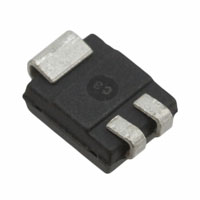


 工商网监
湘ICP备2023018690号
工商网监
湘ICP备2023018690号
