I-Trac™ Daughtercard and RAM Press-In Tool
I-Trac™ Daughtercard Module and RAM Installation
Application Tooling Specification
Press-In Tool
Order No. 62201-8605
FEATURES
�
�
�
Lip provided for positive alignment to connector assembly.
Tool provides uniform distribution of press force across entire pin array.
May be used as a stand-alone tool or mounted in an optional holder with other Molex press-in tools.
SCOPE
Products: I-Trac™ Daughtercard Signal Module Assembly, 75710 Series 6 Column Assemblies, and I-Trac™
RAM, 75910 Series 6 Column Assemblies. See Product List below for specific part numbers.
Product List
The following is a partial list of the product order numbers and their specifications this tool is designed to run.
Updates to this list are available on www.molex.com.
Guide Style Columns
Open
6
75710-0006
75710-2006
Guide Left
6
75710-2606
75710-3306
75710-4006
Guide Right
6
75710-4606
75710-5306
75710 Series Numbers
Assembly Order Number
75710-1006
75710-2106 75710-2206 75710-2306
75710-2706 75710-2806 75710-3006
75710-3406 75710-3506 75710-3606
75710-4106 75710-4206 75710-4306
75710-4706 75710-4806 75710-5006
75710-5406 75710-5506 75710-5606
75910 Series Numbers
Guide Style Columns
Assembly Order Number
Open
6
75910-0603 75910-0605 75910-0606 75910-1603
Left End Wall
6
75910-0613 75910-0615 75910-0616 75910-1613
Right End Wall
6
75910-0623 75910-0625 75910-0626 75910-1623
Dual End Wall
6
75910-0633 75910-0635 75910-0636 75910-1633
75910-2623 75910-2625 75910-2626 75910-2633
75910-3623 75910-3625 75910-3626 75910-3633
Guide Left
6
75910-6623 75910-6625 75910-6626 75910-6633
75910-7623 75910-7625 75910-7626 75910-7633
75910-4623 75910-4625 75910-4626 75910-4633
75910-5623 75910-5625 75910-5626 75910-5633
Guide Right
6
75910-8623 75910-8625 75910-8626 75910-8633
75910-9623 75910-9625 75910-9626 75910-9633
Doc No: ATS-622018605
Revision: D
Release Date: 12-15-05
Revision Date: 02-18-09
75710-2406
75710-3106
75710-3706
75710-4406
75710-5106
75710-5706
75910-1605
75910-1615
75910-1625
75910-1635
75910-2635
75910-3635
75910-6635
75910-7635
75910-4635
75910-5635
75910-8635
75910-9635
UNCONTROLLED COPY
75710-2506
75710-3206
75710-3806
75710-4506
75710-5206
75710-5806
75910-1606
75910-1616
75910-1626
75910-1636
75910-2636
75910-3636
75910-6636
75910-7636
75910-4636
75910-5636
75910-8636
75910-9636
Page 1 of 4
�I-Trac™ Daughtercard and RAM Press-In Tool
Tool Setup
Depending on the number of connectors to be installed and/or the press used, this tool can be used alone or with
a group of press-in tools, mounted in a 62201-95XX rail (ordered separately). See Figure 1.
WITH 62201-95XX
RAIL
ALONE
Figure 1
Tool Installation continued
The 62201-95XX rail is available in a variety of lengths to accommodate multiple press-in tools.
Rail Part Number Rail Overall Length
62201-9501
24mm (0.94 in)
62201-9502
72mm (2.83 in)
62201-9503
156mm (6.14 in)
62201-9504
216mm (8.50 in)
62201-9509
254mm (10.0 in)
62201-9511
305mm (12.0 in)
Reference: This Press-In Tool is 22.3mm (0.88 in.) long.
Printed Circuit Board (PCB) Support
The I-Trac™ connectors require up to 1.81kg (4 lb) of force per pin to press into the PCB. To prevent excessive
PCB flexure and/or damage to the PCB, a support plate is strongly recommended directly beneath the connector
hole pattern.
Due to the custom nature of every application, Molex does not offer any PCB support plate. The customer must
furnish their own support plate.
When creating the PCB support plate, remember to allow clearance for the connector pins as they pass through
the PCB thickness.
Doc No: ATS-622018605
Revision: D
Release Date: 12-15-05
Revision Date: 02-18-09
UNCONTROLLED COPY
Page 2 of 4
�I-Trac™ Daughtercard and RAM Press-In Tool
Press Equipment Recommendations
Many types of presses can be used to install I-Trac™ connectors, but to assure consistent connector installation
Molex recommends the following press criteria:
1. The capability to detect force variations as low as 4.5kg (10 lb) during the press-in cycle; excessive force
measurements should stop the press-in cycle.
2. The rate of pressing can be regulated as low as 0.13mm (0.005 in) per second.
3. Press stroke control to within 0.25mm (0.010 in).
4. Total press stroke must be at least 19mm (0.75 in).
5. For statistical purposes, automatic collection of force and distance data.
Tool Operation
1. Carefully insert, by hand, the Daughtercard and / or RAM module(s) into the PCB hole pattern.
2. Place the application tool on top of the module with the back guide surface of the tool against the back of the
module. See Figure 2.
GUIDE SURFACE
Figure 2
3. Using the application tool and an appropriate press, seat the module until there is less than 0.10mm (.004 in)
clearance between the bottom of the plastic housing and the surface of the PCB. See Figure 3.
0.10
.004
MAX
Figure 3
(Daughtercard shown; same dimensions for RAM)
There should be no broken stand-offs along the perimeter of the part (an indication of over-pressing).
Doc No: ATS-622018605
Revision: D
Release Date: 12-15-05
Revision Date: 02-18-09
UNCONTROLLED COPY
Page 3 of 4
�I-Trac™ Daughtercard and RAM Press-In Tool
CAUTION: To prevent injury, never operate any press without the guards in place. Refer to the press
manufacturer’s instruction manual.
CAUTION: Molex application tooling specifications are valid only when used with Molex connectors and
tooling.
Contact Information
For more information on Molex application tooling please contact Molex at 1-800-786-6539.
Americas Headquarters
Lisle, Illinois 60532 U.S.A.
1-800-78MOLEX
amerinfo@molex.com
Far East North Headquarters
Yamato, Kanagawa, Japan
81-462-65-2324
feninfo@molex.com
Far East South Headquarters
Jurong, Singapore
65-6-268-6868
fesinfo@molex.com
European Headquarters
Munich, Germany
49-89-413092-0
eurinfo@molex.com
Corporate Headquarters
2222 Wellington Ct.
Lisle, IL 60532 U.S.A.
630-969-4550
Fax: 630-969-1352
Visit our Web site at http://www.molex.com
Doc No: ATS-622018605
Revision: D
Release Date: 12-15-05
Revision Date: 02-18-09
UNCONTROLLED COPY
Page 4 of 4
�
很抱歉,暂时无法提供与“62201-8605”相匹配的价格&库存,您可以联系我们找货
免费人工找货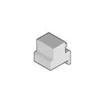


 工商网监
湘ICP备2023018690号
工商网监
湘ICP备2023018690号
