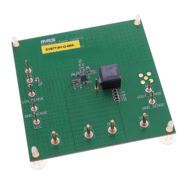
EV8774H-Q-00A
High-Efficiency, 1400kHz, 12A, 18V
Step-Down Converter Evaluation Board
DESCRIPTION
FEATURES
The EV8774H-Q-00A Evaluation Board is
designed to demonstrate the capabilities of
MPS’ MP8774H, a fully-integrated highfrequency, synchronous rectified, step-down,
switch-mode converter with internal power
MOSFETs. It offers a very compact solution to
achieve a 12A continuous output current over a
wide input range, with excellent load and line
regulation. The MP8774H has synchronousmode operation for higher efficiency over the
output current-load range.
Constant On-Time control operation provides
very fast transient response and easy loop
design as well as very tight output regulation.
Full protection features include SCP, OCP,
UVP, and thermal shutdown.
The MP8774H requires a minimal number of
readily-available,
standard,
external
components and is available in a space-saving
QFN-16 (3mmх3mm) package.
ELECTRICAL SPECIFICATION (1)
Parameter
Symbol
Value
Units
Input Voltage
Output Voltage
VIN
VOUT
12
1
V
Output Current
IOUT
12
V
A
Wide 3V-to-18V Operating Input Range
16mΩ/5.5mΩ Low-RDS(ON) Internal Power
MOSFETs
100µA Low IQ Current
High-Efficiency Synchronous-Mode
Operation
Pre-biased Startup
Fixed 1400kHz Switching Frequency
External Programmable Soft Startup Time
EN and Power Good for Power Sequencing
Over-Current Protection and Hiccup
Thermal Shutdown
Available in a QFN-16 (3mmх3mm)
package
APPLICATIONS
Security Camera
Portable Device, XDSL Device
Digital Set-Top Boxes
Flat-Panel Television and Monitors
General Purposes
Notes:
1) For different Input/output voltage specs and different
output capacitor/inductor may need change the application
circuit parameters
All MPS parts are lead-free, halogen free, and adhere to the RoHS
directive. For MPS green status, please visit MPS website under Quality
Assurance.
“MPS” and “The Future of Analog IC Technology” are Registered
Trademarks of Monolithic Power Systems, Inc.
EV8774H-Q-00A EVALUATION BOARD
Efficiency vs. Load Current
VOUT=1V, L=0.33μH, DCR=1.1mΩ
100
EFFICIENCY (%)
95
90
85
80
75
VIN=3.3V
70
VIN=5V
65
Board Number
MPS IC Number
EV8774H-Q-00A
MP8774HGQ
VIN=12V
60
0
2
4
6
8
10
12
LOAD CURRENT (A)
EV8774H-Q-00A Rev.1.0
www.MonolithicPower.com
5/17/2019
MPS Proprietary Information. Patent Protected. Unauthorized Photocopy and Duplication Prohibited.
© 2019 MPS. All Rights Reserved.
1
�EV8774H-Q-00A 18V, 1400kHz, 12A, STEP-DOWN CONVERTER
AGND
PGND
EVALUATION BOARD SCHEMATIC
EV8774H-Q-00A BILL OF MATERIALS
Qty
Ref
C1,C1A,
C2,C2A,
C2B,C2C
C1B,C2D
C3
Value
Description
22μF
Ceramic Cap., 25V,
X5R
1
C4
1μF
1
C5
22nF
1
C6
56pF
1
1
1
1
0
1
1
1
1
R1
R2
R3
R4
R5
R6
R7
R8
L1
20k
30k
0Ω
100k
NS
100k
1k
10Ω
0.33μH
1
U1
MP8774HGQ
6
3
0.1μF
Ceramic Cap., 25V,
X7R
Ceramic Cap., 25V,
X7R
Ceramic Cap., 16V,
X7R
Ceramic Cap., 50V,
C0G
Thick Film Res., 1%
Thick Film Res., 1%
Thick Film Res., 1%
Thick Film Res., 1%
Thick Film Res., 1%
Thick Film Res., 1%
Thick Film Res., 1%
Inductor,DCR=1.1mΩ
Synchronous StepDown Convert
Package
Manufacturer Part Number
0805
muRata
GRM21BR61E226ME44L
0603
muRata
GRM188R71E104KA01D
0603
muRata
GRM188R71E105KA12D
0603
muRata
GRM188R71C223KA01D
0603
muRata
GRM1885C1H560JA01D
0603
0603
0603
0603
0603
0603
0603
0603
SMD
QFN-16
Yageo
Yageo
Yageo
Yageo
RC0603FR-0720KL
RC0603FR-0730KL
RC0603FR-070RL
RC0603FR-07100KL
Yageo
Yageo
Yageo
Wurth
RC0603FR-07100KL
RC0603FR-071KL
RC0603JR-0710RL
7443320033
(3mmх3mm)
MPS
MP8774HGQ
EV8774H-Q-00A Rev.1.0
www.MonolithicPower.com
5/17/2019
MPS Proprietary Information. Patent Protected. Unauthorized Photocopy and Duplication Prohibited.
© 2019 MPS. All Rights Reserved.
2
�EV8774H-Q-00A 18V, 1400kHz, 12A, STEP-DOWN CONVERTER
EVB TEST RESULTS
VIN = 12V, VOUT = 1V, L = 0.33µH, TA = +25°C, unless otherwise noted.
Load Regulation vs. Load Current
Efficiency vs. Load Current
VOUT=1V, L=0.33μH, DCR=1.1mΩ
VOUT=1V
0.5
100
0.4
LOAD REGULATION (%)
EFFICIENCY (%)
95
90
85
80
75
VIN=5V
70
VIN=12V
65
VIN=18V
0.3
0.2
0.1
0
-0.1
-0.2
VIN=5V
-0.3
VIN=12V
-0.4
VIN=18V
-0.5
60
0
2
4
6
8
10
12
0
LOAD CURRENT (A)
2
4
6
8
10
12
LOAD CURRENT (A)
Line Regulation vs. Input Voltage
LINE REGULATION (%)
0.5
0.4
0.3
0.2
0.1
0
-0.1
-0.2
Io=0.01A
-0.3
Io=6A
-0.4
Io=12A
-0.5
3
6
9
12
15
18
INPUT VOLTAGE (V)
EV8774H-Q-00A Rev.1.0
www.MonolithicPower.com
5/17/2019
MPS Proprietary Information. Patent Protected. Unauthorized Photocopy and Duplication Prohibited.
© 2019 MPS. All Rights Reserved.
3
�EV8774H-Q-00A 18V, 1400kHz, 12A, STEP-DOWN CONVERTER
EVB TEST RESULTS (continued)
VIN = 12V, VOUT = 1V, L = 0.33µH, TA = 25°C, unless otherwise noted.
Input/Output Ripple
Input/Output Ripple
IOUT = 0A
IOUT = 0A
CH1:
VOUT/AC
20mV/div.
CH2:
VIN/AC
50mV/div.
CH1:
VOUT/AC
50mV/div.
CH2: VIN/AC
50mV/div.
CH3: VSW
10V/div.
CH3: VSW
10V/div.
CH4: IL
10A/div.
CH4: IL
2A/div.
40ms/div.
2µs/div.
Input/Output Ripple
Start-Up through Input Voltage
IOUT = 12A
IOUT = 0A
CH1:
VOUT/AC
10mV/div.
CH2: VIN/AC
200mV/div.
CH1: VOUT
1V/div.
CHR1: VPG
5V/div.
CH2: VIN
10V/div.
CH3: VSW
10V/div.
CH3: VSW
10V/div.
CH4: IL
2A/div.
CH4: IL
10A/div.
1µs/div.
1ms/div.
Start-Up through Input Voltage
Shutdown through Input Voltage
IOUT = 12A
IOUT = 0A
CH1: VOUT
1V/div.
CHR1: VPG
5V/div.
CH1: VOUT
1V/div.
CHR1: VPG
5V/div.
CH2: VIN
10V/div.
CH3: VSW
10V/div.
CH2: VIN
10V/div.
CH3: VSW
10V/div.
CH4: IL
10A/div.
CH4: IL
10A/div.
1ms/div.
40ms/div.
EV8774H-Q-00A Rev.1.0
www.MonolithicPower.com
5/17/2019
MPS Proprietary Information. Patent Protected. Unauthorized Photocopy and Duplication Prohibited.
© 2019 MPS. All Rights Reserved.
4
�EV8774H-Q-00A 18V, 1400kHz, 12A, STEP-DOWN CONVERTER
EVB TEST RESULTS (continued)
VIN = 12V, VOUT = 1V, L = 0.33µH, TA = 25°C, unless otherwise noted.
Shutdown through Input Voltage
Start-Up through EN
IOUT = 12A
IOUT = 0A
CH1: VOUT
1V/div.
CH1: VOUT
1V/div.
CHR1: VPG
5V/div.
CHR1: VPG
5V/div.
CH2: VEN
5V/div.
CH2: VIN
10V/div.
CH3: VSW
10V/div.
CH3: VSW
10V/div.
CH4: IL
2A/div.
CH4: IL
10A/div.
4ms/div.
2ms/div.
Start-Up through EN
Shutdown through EN
IOUT = 12A
IOUT = 0A
CH1: VOUT
1V/div.
CHR1: VPG
5V/div.
CH1: VOUT
1V/div.
CHR1: VPG
5V/div.
CH2: VEN
5V/div.
CH3: VSW
10V/div.
CH2: VEN
5V/div.
CH3: VSW
5V/div.
CH4: IL
2A/div.
CH4: IL
10A/div.
2ms/div.
400ms/div.
Shutdown through EN
Short-Circuit Protection Entry
IOUT = 12A
IOUT = 0A
CH1: VOUT
1V/div.
CH1: VOUT
1V/div.
CHR1: VPG
5V/div.
CH2: VPG
5V/div.
CH2: VEN
5V/div.
CH3: VSW
10V/div.
CH3: VSW
10V/div.
CH4: IL
10A/div.
CH4: IL
10A/div.
200µs/div.
20ms/div.
EV8774H-Q-00A Rev.1.0
www.MonolithicPower.com
5/17/2019
MPS Proprietary Information. Patent Protected. Unauthorized Photocopy and Duplication Prohibited.
© 2019 MPS. All Rights Reserved.
5
�EV8774H-Q-00A 18V, 1400kHz, 12A, STEP-DOWN CONVERTER
EVB TEST RESULTS (continued)
VIN = 12V, VOUT = 1V, L = 0.33µH, TA = 25°C, unless otherwise noted.
Short-Circuit Protection Recovery
Short-Circuit Protection Steady
State
IOUT = 0A
Short output to GND
CH1: VOUT
1V/div.
CH1: VOUT
1V/div.
CH2: VPG
5V/div.
CH2: VPG
5V/div.
CH3: VSW
10V/div.
CH3: VSW
10V/div.
CH4: IL
10A/div.
CH4: IL
10A/div.
20ms/div.
20ms/div.
Load Transient
IOUT = 6 - 12A
CH1:
VOUT/AC
50mV/div.
CH4: IL
5A/div.
200µs/div.
EV8774H-Q-00A Rev.1.0
www.MonolithicPower.com
5/17/2019
MPS Proprietary Information. Patent Protected. Unauthorized Photocopy and Duplication Prohibited.
© 2019 MPS. All Rights Reserved.
6
�EV8774H-Q-00A 18V, 1400kHz, 12A, STEP-DOWN CONVERTER
PRINTED CIRCUIT BOARD LAYOUT
Figure 1: Top Silk Layer
Figure 2: Top Layer
Figure 3: Inner Layer 1
Figure 4: Inner Layer 2
Figure 5: Bottom Layer
EV8774H-Q-00A Rev.1.0
www.MonolithicPower.com
5/17/2019
MPS Proprietary Information. Patent Protected. Unauthorized Photocopy and Duplication Prohibited.
© 2019 MPS. All Rights Reserved.
7
�EV8774H-Q-00A 18V, 1400kHz, 12A, STEP-DOWN CONVERTER
QUICK START GUIDE
1. Preset Power Supply to12V.
2. Turn Power Supply off.
3. Connect Power Supply terminals to:
a. Positive (+): VIN
b. Negative (–): GND
4. Connect Load to:
a. Positive (+): VOUT
b. Negative (–): GND
5. Turn Power Supply on after making connections. The board will automatically start up.
6. To use the Enable function, apply a digital input to the EN pin. Drive EN higher than 1.4V to turn
on the regulator, or less than 0.9V to turn it off.
NOTICE: The information in this document is subject to change without notice. Please contact MPS for current specifications.
Users should warrant and guarantee that third party Intellectual Property rights are not infringed upon when integrating MPS
products into any application. MPS will not assume any legal responsibility for any said applications.
EV8774H-Q-00A Rev.1.0
www.MonolithicPower.com
5/17/2019
MPS Proprietary Information. Patent Protected. Unauthorized Photocopy and Duplication Prohibited.
© 2019 MPS. All Rights Reserved.
8
�


 工商网监
湘ICP备2023018690号
工商网监
湘ICP备2023018690号
