Reference Only
Spec No. JENF243F-0018K-01
P1/11
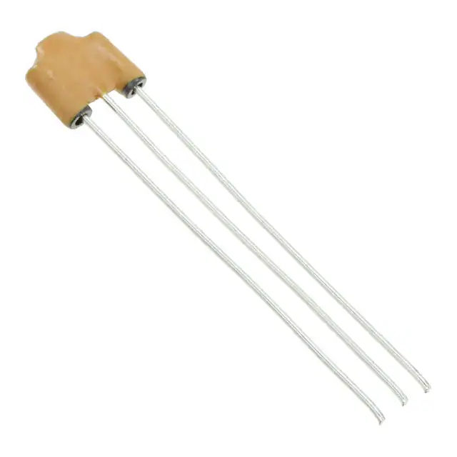
Disc-Type EMIFIL®
(A miniature three-terminal capacitor)
DSS6N□□□□□□□□□□□ Reference Specification
1.Scope
This reference specification applies to DSS6N series.
2.Part Numbering
(Ex.)
DS
S 6 N B3 2A 271 Q93
①
② ③ ④
⑤
⑥
⑦
⑧
① Product ID (Disc-Type EMIFIL®)
② Structure S : Built-in Ferrite Beads Type
③ Style
④ Features
⑤ Temperature Characteristics
⑥ Rated Voltage
⑦ Capacitance
□□□
A
⑨
Marked three digits system.(Ex. 270pF271)
⑧ Lead Type
Q5□/ T□1 : Bulk
(in mm)
Long Lead Type
Straight Lead Type
Q55
Incrimp Lead Type
T51
Lead Length(l)
25.0 min.
Lead Length (l) : See item 9.
Short Lead Type
Q56
Q54
-
T41
6.0±1.0
4.0±0.5
Q9□/ U□1 : Taping
(in mm)
Straight Lead Type
Q91
Q92
Incrimp Lead Type
-
U21
Dimension H
20.0±1.0
16.5±1.0
Dimension H : See item 9.
⑨ Packaging Code
A : Ammo Pack / B : Bulk
Q93
U31
18.5±1.0
3.Rating
Operating temperature : -25 to +85°C
Storage Temperature : -25 to +85°C
Insulation Resistance : 5000M min. (DSS6NB3 / DSS6NE3 /DSS6NZ8)
Rated Current : 6A(DC)
Equivalent Circuit :
1
3
(3)
(1)
GND
2
Others : See Table 1
Table 1
Customer
Part Number
Murata
Part Number
DSS6NB32A220Q55B
DSS6NB32A220Q56B
DSS6NB32A220Q54B
DSS6NB32A220T51B
DSS6NB32A220T41B
DSS6NB32A220Q91A
DSS6NB32A220Q92A
DSS6NB32A220Q93A
DSS6NB32A220U21A
DSS6NB32A220U31A
Temperature
Characteristics
Capacitance
Rated
Voltage
Withstanding
Voltage
±10%
22pF± 20%
100V(DC)
250 V(DC)
MURATA MFG.CO., LTD
Unit Mass
(Typical value)
0.43g
0.43g
0.43g
0.47g
0.47g
0.43g
0.43g
0.43g
0.43g
0.43g
�Spec No. JENF243F-0018K-01
Customer
Part Number
Murata
Part Number
DSS6NB32A330Q55B
DSS6NB32A330Q56B
DSS6NB32A330Q54B
DSS6NB32A330T51B
DSS6NB32A330T41B
DSS6NB32A330Q91A
DSS6NB32A330Q92A
DSS6NB32A330Q93A
DSS6NB32A330U21A
DSS6NB32A330U31A
DSS6NB32A470Q55B
DSS6NB32A470Q56B
DSS6NB32A470Q54B
DSS6NB32A470T51B
DSS6NB32A470T41B
DSS6NB32A470Q91A
DSS6NB32A470Q92A
DSS6NB32A470Q93A
DSS6NB32A470U21A
DSS6NB32A470U31A
DSS6NB32A101Q55B
DSS6NB32A101Q56B
DSS6NB32A101Q54B
DSS6NB32A101T51B
DSS6NB32A101T41B
DSS6NB32A101Q91A
DSS6NB32A101Q92A
DSS6NB32A101Q93A
DSS6NB32A101U21A
DSS6NB32A101U31A
DSS6NB32A151Q55B
DSS6NB32A151Q56B
DSS6NB32A151Q54B
DSS6NB32A151T51B
DSS6NB32A151T41B
DSS6NB32A151Q91A
DSS6NB32A151Q92A
DSS6NB32A151Q93A
DSS6NB32A151U21A
DSS6NB32A151U31A
DSS6NB32A221Q55B
DSS6NB32A221Q56B
DSS6NB32A221Q54B
DSS6NB32A221T51B
DSS6NB32A221T41B
DSS6NB32A221Q91A
DSS6NB32A221Q92A
DSS6NB32A221Q93A
DSS6NB32A221U21A
DSS6NB32A221U31A
Reference Only
Temperature
Characteristics
Capacitance
Rated
Voltage
Withstanding
Voltage
100V(DC)
250 V(DC)
33pF± 20%
47pF± 20%
±10%
100pF±
20%
150pF±
20%
220pF±
20%
MURATA MFG.CO., LTD
P2/11
Unit Mass
(Typical value)
0.43g
0.43g
0.43g
0.47g
0.47g
0.43g
0.43g
0.43g
0.43g
0.43g
0.42g
0.42g
0.42g
0.46g
0.46g
0.42g
0.42g
0.42g
0.42g
0.42g
0.42g
0.42g
0.42g
0.46g
0.46g
0.42g
0.42g
0.42g
0.42g
0.42g
0.42g
0.42g
0.42g
0.46g
0.46g
0.42g
0.42g
0.42g
0.42g
0.42g
0.42g
0.42g
0.42g
0.46g
0.46g
0.42g
0.42g
0.42g
0.42g
0.42g
�Spec No. JENF243F-0018K-01
Customer
Part Number
Murata
Part Number
DSS6NB32A271Q55B
DSS6NB32A271Q56B
DSS6NB32A271Q54B
DSS6NB32A271T51B
DSS6NB32A271T41B
DSS6NB32A271Q91A
DSS6NB32A271Q92A
DSS6NB32A271Q93A
DSS6NB32A271U21A
DSS6NB32A271U31A
DSS6NB32A471Q55B
DSS6NB32A471Q56B
DSS6NB32A471Q54B
DSS6NB32A471T51B
DSS6NB32A471T41B
DSS6NB32A471Q91A
DSS6NB32A471Q92A
DSS6NB32A471Q93A
DSS6NB32A471U21A
DSS6NB32A471U31A
DSS6NB32A102Q55B
DSS6NB32A102Q56B
DSS6NB32A102Q54B
DSS6NB32A102T51B
DSS6NB32A102T41B
DSS6NB32A102Q91A
DSS6NB32A102Q92A
DSS6NB32A102Q93A
DSS6NB32A102U21A
DSS6NB32A102U31A
DSS6NE32A222Q55B
DSS6NE32A222Q56B
DSS6NE32A222Q54B
DSS6NE32A222T51B
DSS6NE32A222T41B
DSS6NE32A222Q91A
DSS6NE32A222Q92A
DSS6NE32A222Q93A
DSS6NE32A222U21A
DSS6NE32A222U31A
DSS6NZ82A103Q55B
DSS6NZ82A103Q56B
DSS6NZ82A103Q54B
DSS6NZ82A103T51B
DSS6NZ82A103T41B
DSS6NZ82A103Q91A
DSS6NZ82A103Q92A
DSS6NZ82A103Q93A
DSS6NZ82A103U21A
DSS6NZ82A103U31A
Reference Only
Temperature
Characteristics
Capacitance
Rated
Voltage
Withstanding
Voltage
100V(DC)
250 V(DC)
270pF±
20%
±10%
470pF±
20%
1000pF±
20%
±
±
20
55
%
30
85%
2200pF±
80
20%
10000pF±
30 %
MURATA MFG.CO., LTD
P3/11
Unit Mass
(Typical value)
0.42g
0.42g
0.42g
0.46g
0.46g
0.42g
0.42g
0.42g
0.42g
0.42g
0.43g
0.43g
0.43g
0.47g
0.47g
0.43g
0.43g
0.43g
0.43g
0.43g
0.42g
0.42g
0.42g
0.46g
0.46g
0.42g
0.42g
0.42g
0.42g
0.42g
0.42g
0.42g
0.42g
0.46g
0.46g
0.42g
0.42g
0.42g
0.42g
0.42g
0.42g
0.42g
0.42g
0.46g
0.46g
0.42g
0.42g
0.42g
0.42g
0.42g
�Spec No. JENF243F-0018K-01
Reference Only
P4/11
4.Testing Conditions
Temperature : Ordinary Temperature 15 to 35°C
: Ordinary Humidity
25 to 85 %(RH)
Humidity
Temperature : 20 ± 2°C
Humidity
: 60 to 70 %(RH)
Atmospheric Pressure : 86 to 106 kPa
5.Style and Dimension
See item 9.
6.Marking
Capacitance
Rated Voltage
Trade Mark
Marked real number.
(22pF to 47pF) Ex. 22pF22
Marked three digits system.(100pF) Ex.1000pF102
Marked voltage value.(100V)
Marked as
7.Performance
No.
7.1
7.2
7.3
7.4
7.5
7.6
Item
Appearance
and
Dimensions
Marking
Capacitance
and
Tolerance
Specification
Meet item 9.
Test Method
Visual Inspection and measured with Slide
Calipers.
Marking is able to be read easily.
Meet item 3.
Visual Inspection.
Table 2
Insulation
Resistance(I.R.)
Withstanding
Voltage
Meet item 3.
Temperature
Characteristics
Meet item 3.
Frequency
Solderability
Capacitance
Products shall not be damaged.
Along the circumference of terminal
shall be covered with new solder at
least 75%.
22pF~100pF
150pF~10000pF
Test Voltage : Rated Voltage
Time : 1 minute through a suitable resistor 1M
Test Voltage : 2.5 times for Rated Voltage
Time : 1 to 5 seconds
Charge Current : 10 mA max.
It shall be applied between input / output terminal
and ground terminal.
Capacitance shall be measured at each step
specified in Table 3 after reaching the thermal
equilibrium.
The capacitance change against the capacitance
at step 3 shall be calculated.
( ) is for DSS6NZ82A103.
Table3
Step
Temp.
(°C)
7.7
Test Voltage
1±0.1MHz 3 V(rms) max.
1±0.1kHz 3 V(rms) max.
1
+20±2
2
-25±2
(-10)
3
+20±2
4
+85±2
(60)
5
+20±2
Flux : Ethanol solution of rosin,25(wt)%
(dipped for 5 to 10 seconds)
Pre-heat : 150±10℃, 60~90 s
Solder : Sn-3.0Ag-0.5Cu
Solder Temperature 245±5℃
Immersion Time : 2 ± 0.5 seconds
Immersion Depth :
2 to 2.5 mm from the bottom of the body.
MURATA MFG.CO., LTD
�Spec No. JENF243F-0018K-01
No.
7.8
Item
Resistance to
Soldering Heat
Specification
Meet Table 4.
Table 4
Appearance
Capacitance
Change
Withstanding
Voltage
7.9
Humidity
Insulation
Resistance
Humidity Life
Insulation
Resistance
Heat Life
B3
E3,
Z8
No damaged.
within ± 10%
within ± 20%
within ± 30%
B3,E3
Z8
No damaged.
B3
within ± 10%
E3
within ± 20%
Z8
within ± 30%
B3,E3
Z8
Insulation
Resistance
No damaged.
B3
within ± 10%
E3
within ± 20%
Z8
within ± 30%
B3,E3
Z8
Test Method
Flux : Ethanol solution of rosin,25(wt)%
(dipped for 5 to 10 seconds)
Pre-heat : 150±10℃, 60~90 s
Solder : Sn-3.0Ag-0.5Cu
Solder Temperature : 270 ± 5 °C
Immersion Time : 3± 0.5 seconds
Immersion Depth :
1.6 ± 0.7 mm from the bottom of the body.
Then measured after exposure in the room
condition for 4 to 24hours.
Temperature : 40 ± 2°C
Humidity : 90 to 95 %(RH)
Time : 500 hours(+24-0 hours)
Then measured after exposure in the room
condition for 4 to 24hours.
Temperature : 40 ± 2°C
Humidity : 90 to 95 %(RH)
Time : 500 hours(+24-0 hours)
Applying Voltage : Rated Voltage
Charge Current : 10 mA max.
Then measured after exposure in the room
condition for 4 to 24hours.
500M min.
Meet Table 7.
Table 7
Appearance
Capacitance
Change
P5/11
1000M min.
Meet Table6.
Table 6
Appearance
Capacitance
Change
7.11
No damaged.
B3
within ± 5%
E3
within ± 15%
Z8
within ± 20%
No damaged.
Meet Table 5.
Table 5
Appearance
Capacitance
Change
7.10
Reference Only
1000M min.
Temperature : 85 ± 3°C
Time : 1000 hours(+48-0 hours)
Applying Voltage :
B3,E3 character : 2 times of DC rated voltage
Z8 character : 1.5times of DC rated voltage
Charge Current : 10 mA max.
Then measured after exposure in the room
condition for 4 to 24hours.
MURATA MFG.CO., LTD
�Reference Only
Spec No. JENF243F-0018K-01
8.Mounting Hole
Bulk
Taping
φ1.0 -3
φ0.8 -3
2.5±0.2
2.5±0.2
2.5±0.2
2.5±0.2
in mm
9.Style and Dimension
(1) Bulk(Straight Lead Type) : Q5□
8.0 max.
2.54 max.
7.0 max.
2
Marking side
Marking side
1.Bottom of dielectric may be exposed.
2.There should not be the exposure
1
of the ferrite bead if a hole is on the
top of ferrite bead.
0.6
Lead Type
Q55
Q56
Q54
l
F1 F1
5.0±0.5
F1=2.5±0.5
1
(3)
2
P6/11
l
25.0 min.
6.0±1.0
4.0±0.5
(in mm)
3
(1)
(2) Bulk (Incrimp Lead Type) : T□1
8.0 max.
2.54 max.
1.Bottom of dielectric may be exposed.
2.There should not be the exposure
2
Detail of forming
1
10.0 max.
Marking side
Marking side
of the ferrite bead if a hole is on the
top of ferrite bead.
1.0±0.2
0
0.6
l
Lead Type
T51
T41
F1 F1
(in mm)
5.0±0.5
F1=2.5±0.5
1
(3)
2
3
(1)
(3) Taping(Straight Lead Type) : Q9□
(All symbols in the illustrations below are described in Table 8)
2.54max.
S
D
F1
F1
2
1 2 3
(3)
(1)
D0
t1
P0
d
l
W0
L
W1
W
F
W2
1
P1
h2
h1
7.0
max.
P
H
P2
t2
l
25.0 min.
4.0±0.5
(in mm)
1.Bottom of dielectric may be exposed.
2.There should not be the exposure of the ferrite bead if a hole is on the top of ferrite bead.
MURATA MFG.CO., LTD
�Reference Only
Spec No. JENF243F-0018K-01
(4) Taping (Incrimp Lead Type) : U□1
P2
2.54max.
s
D
P
h1
F1
F1
W2
F
2
W0
t1
t2
d
l
D0
1 2 3
(3)
(1)
P0
h2
H
1
P1
L
W1
W
10.0max.
Detail of forming
0.2
1.0+
-0
P7/11
1.Bottom of dielectric may be exposed.
2.There should not be the exposure of the ferrite bead if a hole is on the top of ferrite bead.
Table 8
Code
Description
Dimensions
P
Pitch of Component
P0
P1
Pitch of Sprocket Hole
Length from Hole Center to Lead
Length from Hole Center
to Component Center
Width of Body
Deviation along tape, Left or Right
Carrier Tape Width
Position of Sprocket Hole
Protrusion Length
Diameter of Sprocket Hole
Lead Diameter
Total Tape Thickness
Total Thickness,Tape and Lead Wire
Deviation across Tape,front
Deviation across Tape,rear
Portion to Cut in Case of Defect
Hold Down Tape Width
Hold Down Tape Position
P2
D
S
W
W1
l
D0
d
t1
t2
h1
h2
L
W0
W2
H
F
F1
12.7
Lead length between sprocket
hole and forming position
Lead Spacing
Remark
Product Inclination
S Determines Crossing
12.7±0.2
3.75±0.7
6.35±1.3
Q91
Q92
U21
Q93
U31
7.0 max.
0±1.0
17.0±0.5
9.0+0,-0.5
+0.5 -1.0
4.0±0.1
0.6
0.7±0.2
1.5 max.
1.0 max.
1.0 max.
11.0+0,-1.0
12.0±0.5
1.5±1.5
20.0±1.0
Shift In Tape
In Direction of Feed
Tape Widthwise Shift
Includes Thickness of
Bonding Tape
16.5±1.0
18.5±1.0
5.0+0.7,-0.2
2.5+0.4,-0.2
(in mm)
MURATA MFG.CO., LTD
�Reference Only
Spec No. JENF243F-0018K-01
10.Taping
10.1 Supplement condition of taping
P8/11
(1) A maximum of 0.3% of the components quantity per reel or Ammo pack may be missing without consecutive
missing components.
(2) The adhesive power of the tape shall have over 2.94N at the following condition.
F 2.94 N
Hold down tape
Carrier tape
(3) Splicing method of tape
1. Carrier tape
Carrier tape shall be spliced by cellophane tape.
Overall thickness shall be less than 1.05 mm.
Direction of feed
Overall thickness
Hold down tape
Carrier tape
30 to 50
Cellophane tape
(in mm)
2. Hold down tape
Hold down tape shall be spliced with overlapping.
Overall thickness shall be less than 1.05 mm.
Direction of feed
20 to 30
Hold down tape
Hold down tape
Carrier tape
(in mm)
Overall thickness
3. Both carrier tape and hold down tape
Both tapes shall be cut zigzag and spliced with splicing tape.
11. Packing
11.1 Packing quantity
The standard packing quantity is as follows.
(The packing quantity may be changed due to a fraction of order.)
Minimum Packing Form and Quantity
A Unit Quantity
Standard Quantity
Bulk : in a plastic bag
in a container
Taping : in an ammo pack (corrugated cardboard box)
Long Lead Type (Q55/T51)
250 pcs.
5000 pcs.
Bulk
Short Lead Type (Q54/Q56/T41)
500 pcs.
10000 pcs.
Taping (Q91/ Q92/ Q93/U21/U31)
2000 pcs.
20000 pcs.
A quantity in a container is depending on a quantity of an order.
Terminal Configuration
11.2 Packing Form
(1) Bulk
1.Products are packed into a plastic bag.
2.The plastic bags are put into a container
(corrugated cardboard box) depending on a
quantity of an order.
the plastic bag with products
a plastic bag
a container
container label
MURATA MFG.CO., LTD
�Reference Only
Spec No. JENF243F-0018K-01
P9/11
(2) Taping
1 .Folding the tape per 25 pitches,products are packed into an ammo package so that each product of each
layer wound zigzag is put on top of one another. [Fig 1]
2. The dimensions of the ammo package are indicated in [Fig 2].
3. The ammo packages are put into a container (corrugated cardboard box) depending on a quantity of an
order.
4. Not less than 3 consecutive of component shall be missing on both edge of tape.
[Fig 1] zig zag
[Fig 2]
240 max.
340 max.
label
The unloading direction : Right
The hold down tape : Upper
The product body : Left along the unloading direction
51 max.
(in mm)
12.Marking on package
12.1 Unit Package
Bulk : Marked on a plastic bag.
Taping : Marked on a label stuck on an ammo package.
Marking on a unit package consists of :
Customer part number, MURATA part number, Inspection number(1), RoHS marking (2), Quantity, etc
1) « Expression of Inspection No. »
□□ OOOO
(1)
(1) Factory Code
(2) Date
(2)
(3)
First digit
: Year / Last digit of year
Second digit
: Month / Jan. to Sep. 1 to 9, Oct. to Dec. O,N,D
Third, Fourth digit : Day
(3) Serial No.
2) « Expression of RoHS marking »
ROHS – Y (△)
(1) (2)
(1) RoHS regulation conformity parts.
(2) MURATA classification number
12.2 Container
Marking on the label stuck on a container consists of :
Customer name Purchasing Order Number, Customer Part Number, MURATA part number,
RoHS marking (2), Quantity, etc
13.
△Caution
!
13.1 Mounting holes
Mounting holes should be designed as specified in this specifications.
Or different design from this specifications may cause cracks in ceramics which may lead to smoking / firing.
13.2 Caution for the product angle adjust work
Take care not to apply any mechanical stress to product body at the lead terminal bending process for product
angle adjustment after insertion.
13.3 Limitation of Applications
Please contact us before using our products for the applications listed below which require especially high
reliability for the prevention of defects which might directly cause damage to the third party's life, body or
property.
(1) Aircraft equipment
(7) Traffic signal equipment
(2) Aerospace equipment
(7) Disaster prevention / crime prevention equipment
(3) Undersea equipment
(9) Data-processing equipment
(4) Power plant control equipment (10) Applications of similar complexity and /or reliability requirements
to the applications listed in the above
(5) Medical equipment
(6) Transportation equipment (vehicles, trains, ships, etc.)
MURATA MFG.CO., LTD
�Reference Only
Spec No. JENF243F-0018K-01
14. Notice
14.1 Soldering
P10/11
(1) Use rosin-based flux. Do not use strong acidic flux with halide content exceeding 0.2(wt)%
(chlorine conversion value).
Use Sn-3.0Ag-0.5Cu solder
T e m p e ra tu re (° C )
(2) Standard flow soldering profile.
Pre- heating(in air)
300
Soldering
Gradual Cooling
(in air)
Solder temp.
250
Solder
temperature
250~260 °C
200
150
100
Soldering
time
4~6s
50
1 minutes min. Soldering time
(3) Resistance to soldering iron goes in the following condition that tip temperature is 350 °C max. and
soldering time is 5 s max.
(4) Products and the leads should not be subjected to any mechanical stress during soldering process.
(and also while subjected to the equivalent high temperature.)
14.2 Cleaning
Products shall be cleaned on following conditions.
(1) Cleaning Temperature: 60℃ max.(40℃ max. for Isopropyl alcohol).
(2) Ultrasonic cleaning shall comply with the following conditions, avoiding the resonance phenomenon at the
mounted products and P.C.B.
Power:20W / l max.
Frequency:28kHz 40kHz
Time :5 minutes max.
(3) Cleaning agent
1. alcohol cleaning agents.
・Isopropyl alcohol (IPA)
2. Aqueous cleaning agent
・Pine Alpha ST-100S
(4) Ensure that residual flux and residual cleaning agent is completely removed.
Products should be thoroughly dried after aqueous agent has been removed with de-ionized water.
(5) For other cleaning methods, please contact Murata engineering.
14.3 Operating Environment
(1) Do not use products in corrosive gases such as chlorine gas, acid or sulfide gas.
(2) Do not use products in the environment where water, oil or organic solvents may adhere to products.
(3) Do not adhere any resin to products, coat nor mold products with any resin (including adhesive)to prevent
mechanical and chemical stress on products.
14.4.Storage and handling requirements.
(1) Storage period
Use the products within 12 months after delivered.
Solderability should be checked if this period is exceeded.
(2) Storage environment condition
To prevent products quality deterioration, stored conditions should be controlled as follows ;
1. Temperature : -10 to 40 degrees centigrade
2. Humidity
: 15 to 85% relative humidity
3. Products should be stored without sudden changes in temperature and humidity.
Don't keep products in corrosive gases such as sulfur,chlorine gas or acid,
or it may cause oxidization of lead terminals resulting in poor solderability.
4. Products should be stored on the palette for the prevention of the influence from humidity, dust and so on.
5. Products should be stored in the warehouse without heat shock, vibration,direct sunlight and so on.
(3) Handling Conditions
Care should be taken when transporting or handling product to avoid excessive vibration or mechanical
shock.
MURATA MFG.CO., LTD
�Spec No. JENF243F-0018K-01
15.
Reference Only
P11/11
△Note
!
(1)Please make sure that your product has been evaluated in view of your specifications with our product being
mounted to your product.
(2)You are requested not to use our product deviating from the reference specifications.
(3)The contents of this reference specification are subject to change without advance notice. Please approve
our product specifications or transact the approval sheet for product specifications before ordering.
MURATA MFG.CO., LTD
�


 工商网监
湘ICP备2023018690号
工商网监
湘ICP备2023018690号
