MAPC-104 PC/104-Plus Series
www.murata-ps.com
Non-Isolated, DC/DC Converters
3.3, 5.1 & 12.4, 46W Mobile Applications
FEATURES
46 Watts for Mobile Access Router to
IP/Networks
PC/104-Plus compatible/stackable, powering Cisco system cards
9 to 32V input range, supporting both
12V and 24V vehicle batteries
Reverse input voltage protection
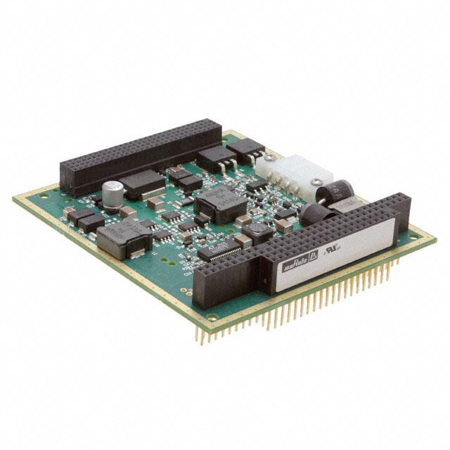
Typical unit
Automotive transient protection
Efficiency to 92.5% @ full load
PRODUCT OVERVIEW
No derating to +85°C, 100 lfm
Independently regulated +3.3V, +5.1V
and +12V outputs
Power up/down sequencing
Murata Power Solutions’ MAPC-104 non-isolated,
triple output DC/DC converter is designed to
power the Cisco 3200 Mobile Access Router and
is compliant to PC/104-Plus specifications. The
equipment ideally suites integration into public
safety, defense, homeland security and commercial
transportation vehicles, whether on land, in water
or air, and is employed for powering secure data,
voice and video communications across multiple
wireless networks.
The MAPC-104 is a high performance, compact
and rugged power supply which operates in the
harshest conditions, withstanding input transient
voltages according to SAE J1455 and J1211. It
converts the vehicle’s standard battery voltage of
12V or 24V (VIN range from 9 to 32 Volts) to three
fully regulated outputs of 3.3V @ 6A, 5.1V @ 6.3A
and 12V @ 100mA up to a total output power of
46 Watts. Taking full advantage of a synchronousrectifier, buck/boost topology, MAPC-104’s boast
outstanding efficiency of up to 92.5%, enabling
full-power operation to ambient temperatures as
high as +85°C with 100 lfm air flow.
Low 25mVp-p ripple/noise
Power good LED and external signal
Compact 3.775” × 3.55” × 0.6” package,
standard PC/104-plus pinout
Stable no-load condition
Thermal shutdown with warning
Fully I/O protected
UL/IEC/EN60950-1 certification pending
The compact 3.775” x 3.55” x 0.60” (95.9 x
90.2 x 15.2mm) open frame, triple output DC/DC
power card is mechanically and electrically compliant to PC/104-plus specifications. Operating with
the Cisco designed system cards, the MAPC-104
is considered part of the host, which requires the
3.3V (but no –5V/–12V) supply provided.
Assembled using fully automated, SMT-on-pcb
techniques, MAPC-104s provide stable no-load
operation, excellent line and load regulation
(±1% max.), quick step response (200μsec), and
low output ripple/noise (25mVp-p).
All devices feature full I/O fault protection
including: input overvoltage and undervoltage
shutdown, power up/down sequencing, output
overvoltage, output current limiting, short-circuit
protection, power good (LED indicator and external
signal), overtemperature warning and thermal
shutdown.
All models are certified to IEC/EN/UL60950-1
safety standards. Selected models include RoHS
compliance.
Performance Specifications➀
Output
Model
MAPC-104
Output 1
Output 2
Output 3
IOUT (Amps)
Input
R/N (mVp-p) ➁
Regulation (Max.) ➂
VIN (Volts)
Range
Min.
Typ.
12
9-32
35/4
91%
92.5%
24
9-32
35/4
89.5%
91%
Nom.
Max.
Typ.
Max.
Line
Load
Nom.
3.3
5.1
12
5
5.46
0.07
6
6.3
0.1
25
25
20
35
50
35
±1%
±1%
±1%
±1%
±1%
±1%
➀ Typical at TA = +25°C under nominal line voltage and nominal-load conditions, unless noted.
➁ Ripple/Noise (R/N) is tested/specified over a 20MHz bandwidth. All models are specified
with an external 0.1μF multi-layer ceramic capacitor installed across each output pin.
Efficiency
IIN ➃
(mA/A)
VOUT
(Volts)
Package/
Pinout
C46
See pages 2, 3
for Pinout
➂ Devices have no minimum-load requirements and will regulate under no-load conditions.
Regulation specifications describe the output-voltage deviation as the line voltage or load
is varied from its midpoint value to either extreme.
➃ Nominal line voltage, no-load/full-load conditions.
For full details go to
www.murata-ps.com/rohs
www.murata-ps.com/support
MDC_MAPC-104.B02 Page 1 of 7
�MAPC-104 PC/104-Plus Series
Non-Isolated, DC/DC Converters
3.3, 5.1 & 12.4, 46W Mobile Applications
MECHANICAL SPECIFICATIONS
�����������
���������� $)!�
��0,!#%3
Case C46
�����������
���������
" !
ORDERING GUIDE & PART NUMBER STRUCTURE
�
)0(
*�
# $
����
�����
������ ������
�����
������
Model Number
Auxiliary Power
Connector (P2)
MAPC-104
Not installed
MAPC-104-5V
Installed
MAPC-104 - 5V - C
�
*�
�
*�
$#"!
0�
����
�����
�����490�
�����
����
������
�
����
�����
����
������
�����490�
�����
�����-!8������
-!8)-5#/-0/.%.4(%)'(4
�����
�����
PC/104-Triple
Output Power
Converter
����
�����
Auxiliary Power
Connector (P2)
Blank = Not installed
5V = P2 is installed
RoHS Hazardous
Substance Compliance
Y = RoHS-5 (with lead)
C = RoHS-6 (no lead)
�����
������
�����
�����
�����
������
����������
-!8)-5#/-0/.%.4(%)'(4
Dimensions are in inches (mm)
0).�
'2/5.$
�����
������
�����
�����
0).�
��6DC0/7%2/54
����������
315!2%0/343�
�0/3)4)/.3
����
�����
�����
������
����
�����
����
�����
5 Volt Auxiliary Power Connector, P2 (Optional)
�
�
�
�
Figure 1. MAPC-104 Input Power Head
)0(
TOP VIEW
Pin
1
2
3
4
IPH Mating connector: Molex 5557 (39-01-4040)
Assignment
Functional Description
OT_Warn Out
Overtemperature Warning
Pwr_LED_Drive Out
External Power Good LED Driver
Input Ground
VIN–
Positive Input
VIN+
www.murata-ps.com/support
MDC_MAPC-104.B02 Page 2 of 7
�MAPC-104 PC/104-Plus Series
Non-Isolated, DC/DC Converters
3.3, 5.1 & 12.4, 46W Mobile Applications
Figure 2. MAPC-104 (PC/104-plus) Bus Signal Assignments
Figure 3. MAPC-104 (PC/104-Reference) Bus Signal Assignments
J3/P3
J1/P1
Pin
A
B
C
D
Pin
A
B
1
GND ➁
Reserved
+5.1V
AD00
1
IOCHCK*
GND
2
VI/O
AD02
AD01
+5.1V
2
D7
RSTDRV
3
AD05
GND
AD04
AD03
3
D6
+5.1V
4
C/BE0*
AD07
GND
AD06
4
D5
IRQ9
5
GND
AD09
AD08
GND
5
D4
NA (–5V) ➂
6
AD11
VI/O
AD10
M66EN
7
AD14
AD13
GND
AD12
8
+3.3V
C/BE1*
AD15
+3.3V
Pin
D
9
SERR*
GND
SB0*
PAR
0
GND
10
GND
PERR*
+3.3V
SDONE
1
MEMCS16*
11
STOP*
+3.3V
LOCK*
GND
2
12
+3.3V
TRDY*
GND
DEVSEL*
3
13
FRAME*
GND
IRDY*
+3.3V
14
GND
AD16
+3.3V
15
AD18
+3.3V
AD17
16
AD21
AD20
17
+3.3V
AD23
18
IDSEL0
GND
IDSEL1
IDSEL2
9
19
AD24
C/BE3*
VI/O
IDSEL3
10
6
D3
DRQ2
7
D2
NA (–12V) ➂
C
8
D1
ENDXFR*
GND
9
D0
+12V
SBHE*
10
IOCHRDY
KEY ➁
IOCS16*
LA23
11
AEN
SMEMW*
IRQ10
LA22
12
A19
SMEMR*
4
IRQ11
LS21
13
A18
IOW*
C/BE2*
5
IRQ12
LS20
14
A17
IOR*
GND
6
IRQ15
LS19
15
A16
DACK3*
GND
AD19
7
IRQ14
LA18
16
A15
DRQ3
AD22
+3.3V
8
DACK0*
LA17
17
A14
DACK1*
DRQ0
MEMR*
18
A13
DRQ1
DACK5*
MEMW*
19
A12
REFRESH*
SYSCLK
J2/P2
20
GND
AD26
AD25
GND
11
DRQ5
SD8
20
A11
21
AD29
+5.1V
AD28
AD27
12
DACK6*
SD9
21
A10
IRQ7
22
+5.1V
AD30
GND
AD31
13
DRQ6
SD10
22
A9
IRQ6
23
REQ0*
GND
REQ1*
VI/O
14
DACK7*
SD11
23
A8
IRQ5
24
GND
REQ2*
+5.1V
GNT0*
15
DRQ7
SD12
24
A7
IRQ4
25
GNT1*
VI/O
GNT2*
GND
16
+5.1V
SD13
25
A6
IRQ3
26
+5.1V
CLK0
GND
CLK1
17
MASTER*
SD14
26
A5
DACK2*
27
CLK2
+5.1V
CLK3
GND
18
GND
SD15
27
A4
TC
28
GND
INTD*
+5.1V
RST*
19
GND
KEY ➁
28
A3
BALE
+5.1V
29
+12V
INTA*
INTB*
INTC*
29
A2
30
NA (–12V) ➂
Reserved
Reserved
3.3V KEY ➁
30
A1
OSC
31
A0
GND
32
GND
GND
➀ The shaded area denotes power or ground signals.
➁ The KEY pins are to guarantee proper module installation:
J3/P3, pin A1 is electrically connected to GND for shielding
J3/P3, pin D30 is removed and the female side is plugged for 3.3V I/O
J2/P2, pin C19 is keyed, pin is removed and the female side is plugged
J1/P1, pin B10 is keyed, pin is removed and the female side is plugged
➂ J3/P3, pin A30 and J1/P1, pins B5 and B7 are not used. Pin assignments for –5V and –12V are for reference only.
Auxiliary 5V Power Connector, P2
Specifications (typical unless noted)
+5 Vdc at 1 Amp maximum
Power Output➀
Power Characteristics
See MAPC-104 Specifications
P2 Header Type
AMP/Tyco Electronics 640455-2
Contact Dimensions
Two 0.025" square posts, 0.3" long, 0.10"
spacing on centers. See drawings.
Contact Material
Tin plating over copper alloy
Contact Assembly Force 3 lbs. (13N)
Single-row, 2-position IDC on 0.10" spacing
Mating Connector➁
Environmental
Compatible with host MAPC-104 system
➀ The contacts are rated at 5 Amps 250Vac. However, whatever current is drawn
must be summed with current powering the PC-104 system.
➁ A suggested mating connector is AMP/Tyco Electronics MTA-100 Series,
part number 647000-2. See also the CST-100 Series.
For the MAPC-104-5V model version, spare +5 Vdc power may be taken from the
P2 connector which is adjacent to the pin 1 end of the J1 connector (see drawings).
Be aware that this power is generated on the MAPC-104 and therefore is in
addition to whatever 5V current is used by the host PC-104 system. All power
characteristics (regulation, tempco, ripple, etc.) are derived from the MAPC-104.
www.murata-ps.com/support
MDC_MAPC-104.B02 Page 3 of 7
�MAPC-104 PC/104-Plus Series
Non-Isolated, DC/DC Converters
3.3, 5.1 & 12.4, 46W Mobile Applications
Performance/Functional Specifications
Typical @ TA = +25°C under nominal line voltage and full-load conditions unless noted. ➀
Input
Input Voltage Range
Transient Voltage Protection
Overvoltage Shutdown
Overvoltage Protection
Start-Up Threshold ➁
Undervoltage Shutdown ➁
9–32 Volts (12V or 24V battery)
125V/100ms (30kVA)
32–36 Volts (34V typical)
48V/5 minutes
9–10 Volts (9.4V typical)
7–9 Volts (8.2V typical)
Input Current
Input Reflected Ripple Current ➂
Internal Filter Type
See Performance Specifications
45mVp-p
Pi
Reverse-Polarity Protection
Yes (external fuse mandatory)
Output
Minimum Loading Per Output
Maximum Capacitive Load
No load
2000µF (+3.3V)
1000µF (+5.1V)
500µF (+12V)
±3% maximum
VOUT Accuracy (50% load)
Temperature Coefficient
Ripple/Noise (20MHz BW)
Line/Load Regulation
Efficiency
Current Limit Inception ➃
(97% VOUT, each other
output @ 0 Amps
Short Circuit Current
(Zener)
±0.02%/°C
See Performance Specifications
See Performance Specifications
See Performance Specifications
7-9 Amps (+3.3V)
8.5-11 Amps (+5.1V)
0.2-0.5 Amps (+12V)
2.65 Amps (+3.3V)
3.24 Amps (+5.1V)
0.12 Amps (+12V)
3.9V (+3.3V)
6V (+5.1V)
13V (+12V)
See Tech Notes
(LED and external Signal)
Overvoltage Protection ➈
Power Good
within 7-10% of VOUT
Dynamic Characteristics
Dynamic Load Response ➄
(50-100% step to within 1% of VOUT)
Power-up Sequencing ➅
(5.1V power-down before 3.3V)
Power-down Sequencing ➁
(5.1V power-down before 3.3V)
Switching Frequency
200µsec (+3.3V & +5.1V)
100µsec (+12V)
2-6msec
1-4msec
320 kHz (+3.3V & +5.1V)
1120 kHz (+12V
Environmental
Calculated MTBF ➆
Operating Ambient Temperature ➇
With 100 lfm Air Flow, no derating
Board Temperature
3,129,938 hours
Thermal Shutdown
+112°C to 118°C
Thermal Shutdown Warning
27 to 33 seconds
2nd Level Thermal Shutdown
+122 to +128°C
Storage Temperature
–40 to +85°C
–40 to +105°C
–40 to +105°C
Physical
Dimensions
Connector and Pin Material
Weight
See Mechanical Specifications
According to PC/104-plus Spec
3.6 ounces (102 grams)
Insulation Level
Non-isolated
➀ All models are tested and specified with a single, external, 0.1μF, multi-layer ceramic
➁
➂
➃
➄
➅
➆
➇
➈
output capacitor on each output and no external input capacitors, unless otherwise noted.
All models will effectively regulate under no-load conditions (with perhaps a slight increase
in output ripple/noise).
See Technical Notes/Performance Curves for additional explanations and details.
Input Ripple Current is tested/specified over a 5-20MHz bandwidth with an external 33μF
input capacitor and a simulated source impedance of 220μF and 12μH. See I/O Filtering,
Input Ripple Current and Output Noise for details.
The Current-Limit-Inception point is the output current level at which the converter’s
power-limiting circuitry drops the output voltage 3% from its initial value. See Output
Current Limiting and Short-Circuit Protection for more details.
See Dynamic Load Response for detailed results including switching frequencies.
For Start-Up-Time specifications, output settling time is defined as the output voltage
having reached ±1% of its final value and the load current having reached at least 80% of
its final value.
MTBF is calculated using TELCORDIA SR-332 Method 1 Case 3, Issue 1, ground fixed,
+30°C ambient air and full-load conditions.
All models are fully operational and meet all published specifications, including “cold start,”
at –40°C.
The highly unlikely, simultaneous failure of several specific on-board components could
result in the MAPC-104’s input voltage appearing at its output, despite the unit’s output
overvoltage protection mechanisms. In this rare situation, the Power Good signal (IPH pin
2, Pwr_LED_Drive) will be deactivated and systems monitoring Power Good will eventually
shut down. If you are using an MAPC-104 to power a load that must be protected against
any and all possible overvoltages, no matter how rare, you will have to provide the protection external to the MAPC-104. Please contact MPS for recommendations.
Absolute Maximum Ratings
Input Voltage:
Continuous
Up to 5 minutes maximum
Transient
36 Volts
48 Volts
125V (30kVA)
Input Reverse-Polarity Protection
External fuse mandatory
Output Current
Current limited. Devices can withstand
sustained output short circuit.
These are stress ratings. Exposure of devices to any of these conditions may adversely affect
long-term reliability. Proper operation under conditions other than those listed in the Performance/
Functional Specifications Table is not implied.
Connector Designations
The official PC/104 bus specification identifies the standard interboard bus
connections as paired J1/P1 and J2/P2 on one side and J3/P3 on the other
side. However, J1/P1/J2/P2 is physically all one big 4-row connector with
J1/J2 bus receptacle sockets (female) on the top side and P1/P2 pins (male) on
the bottom. This arrangement provides interboard pass-through connections
between PC/104 boards. MPS refers to this single connector as “J1.”
MPS’s auxiliary connectors (the IPH and the 5V Auxilliary Power Connector)
are internally designated P1 and P2 respectively and this nomenclature may
appear on the board silkscreening. This is purely an artifact of automated
sequential part numbering in our CAD system and has no relation to the
standard PC/104 interboard bus connectors. Don’t get the connectors confused
since they are all very different types and locations!
www.murata-ps.com/support
MDC_MAPC-104.B02 Page 4 of 7
�MAPC-104 PC/104-Plus Series
Non-Isolated, DC/DC Converters
3.3, 5.1 & 12.4, 46W Mobile Applications
Typical Performance Curves
3.3VOUT Efficiency vs. Line Voltage and Load Current
(5.1V @ 5.46A and 12V @ 0.07A)
Efficiency vs. Line @ 46W
94
94
93
93
92
92
91
91
VIN = 9V
Efficiency (%)
Efficiency (%)
VIN = 12V
90
89
VIN = 24V
90
89
VIN = 32V
88
88
87
87
86
86
9
12
18
24
28
32
0
1.25
Input Voltage (V)
2.5
3.75
5
6.3
0.08
0.1
Load Current (Amps)
5.1VOUT Efficiency vs. Line Voltage and Load Current
(3.3V @ 5A and 12V @ 0.07A)
12VOUT Efficiency vs. Line Voltage and Load Current
(5.1V @ 5.46A and 3.3V @ 5A)
94
94
VIN = 9V
93
93
VIN = 9V
92
91
Efficiency (%)
Efficiency (%)
92
VIN = 12V
90
VIN = 24V
89
91
VIN = 12V
90
VIN = 24V
89
VIN = 32V
VIN = 32V
88
88
87
87
86
86
0
1.25
2.5
3.75
Load Current (Amps)
5
6.3
0
0.02
0.04
0.06
Load Current (Amps)
www.murata-ps.com/support
MDC_MAPC-104.B02 Page 5 of 7
�MAPC-104 PC/104-Plus Series
Non-Isolated, DC/DC Converters
3.3, 5.1 & 12.4, 46W Mobile Applications
Self-Protection Features
The MAPC-104 contains two systems for protection of out-of-limit voltages,
currents and temperature. These systems control two output lines located on
the Input Power Header connector. Both systems operate independently and
concurrently. The MAPC-104 will respond to both temperature and voltage/
current simultaneously.
The output circuits for both these controls are shown below. Both of them
will drive either an external LED lamp and/or a logic circuit. The Overtemperature Warning Circuit assumes that an external pullup resistor is supplied by
the user. The Power Good Circuit (“Pwr_LED_Drive Out”) includes an on-board
pullup resistor to drive an external LED with about 15mA.
/4?7ARN/UT
HI (transistor off) = Power is normal. LED lamp is illuminated.
LO (transistor on) = Power fault, LED lamp is dark
Overtemperature Operation
The overtemperature system includes a on-board temperature sensor, a local
microcontroller with A/D inputs, a timer and hysteresis so that the user may
take steps to prevent inadvertant shut down. Operation proceeds as follows:
If the on-board temperature exceeds +115°C, the OT_Warn Output is asserted
(LO) by the microcontroller and an internal 30 second software timer is started.
The outputs remain powered on.
If the 30-second timer has not expired and the on-board temperature cools
below +110°C, the OT_Warn Output will be deasserted (HI) and operation will
continue unchanged.
�
#/.42/,,%2
--"4����
���M7
MAXIMUM
n6).
Pwr_LED_Drive Out (pin 2, pullup to internal +5V):
If the 30-second timer has expired and the temperature still exceeds
+115°C, the outputs will shut down. As soon as the on-board temperature
cools to less than +110°C, the MAPC-104 will automatically restart and power
will be restored to the outputs.
#/--/.
�
The 5 degree hysteresis between 110 and 115°C prevents rapid cycling of
the OT_Warn Output.
8 �)NPUT0OWER(EADER�)0( PINS
Typical External Logic Wiring
If the on-board temperature reaches +125°C, the outputs will shut down,
regardless of the state of the 30-second timer. The temperature must cool to
less than +110°C for auto restart.
���K7
��6DC
��6DC
�
/4?7ARN/UT
()�4EMPERATURENORMAL
,/�/VERTEMPERATURE
,/')##/--/.
�
���7
0WR?,%$?$RIVE/UT
�
n6).
#/.42/,,%2
"33���
Typical OT Warning External LED Lamp Wiring
n6).
��6DC
�
#/--/.
�
/4?7ARN/UT
8 �)NPUT0OWER(EADER�)0( PINS
���7
Typical Power Good External LED Lamp Wiring
,/')##/--/.
�
n6).
Figure 1. Overtemperature Warnimg Circuit
��M!
The transistors in these outputs are either on (typically less than 0.4 Volts out)
or off (high impedance state). Depending on how the user wires the external
circuit, these indicators have the following sense:
�
()�0OWERISNORMAL
,/�&AULT
�
Figure 2. Overtemperature Warnimg Circuit
OT_Warn Out (pin 1):
HI (transistor off) = Temperature is normal
LO (transistor on) = Over temperature condition
www.murata-ps.com/support
MDC_MAPC-104.B02 Page 6 of 7
�MAPC-104 PC/104-Plus Series
Non-Isolated, DC/DC Converters
3.3, 5.1 & 12.4, 46W Mobile Applications
Power Good Operation
Local power is measured by several circuits shared with the overtemperature
system. The Pwr_LED_Drive Output is indirectly controlled by the on-board
microcontroller. The on-board PWM switching controller measures +3.3V and
+5V output voltages and all output currents. The microcontroller measures
input voltage and the +12V output voltage. The system requires that the input
voltage is within normal tolerances at all times. If the input voltage is too
high very briefly at startup (but not exceeding the absolute input voltage), the
system will start normally if the input voltage reaches acceptable limits quickly
(under half a second). This typically occurs as a load is applied.
When the system first starts, the Power Good LED (if installed) remains dark
briefly until all on-board startup conditions are met (less than half a second) at
which point the LED is illuminated. The operation proceeds as follows:
If the fault condition remains, the system will attempt to restart two more
times, spaced about half a second apart. If the fault remains for the third time,
the system will shut down and will not retest the fault. The system must now
be restored by fully cycling the input power.
The 3-fault countdown only occurs if the fault does not recover continuously
throughout the attempted restart interval. An occasional random shutdown and
successful restart will not trigger the 3-fault counter. However, external logic
should record the frequency and quantity of such shutdowns.
RoHS-5 compliance refers to the exclusion of the six hazardous substances
in the RoHS specification with the exception of lead. MPS’s RoHS-5 products
use all the conforming RoHS materials, however our solders are Sn63/Pb37.
If the outputs on any lines deviate from approximately ±7% of nominal
and/or the output current is excessive, the outputs are all shut down and the
Pwr_LED_Drive Output is desasserted (LO, lamp dark). The system will attempt
to restart in about half a second by briefly turning on all outputs. If successful and
the fault is eliminated, the Pwr_LED_Drive Output will be asserted (HI, lamp lit)
and operation continues.
Murata Power Solutions, Inc.
11 Cabot Boulevard, Mansfield, MA 02048-1151 U.S.A.
ISO 9001 and 14001 REGISTERED
This product is subject to the following operating requirements
and the Life and Safety Critical Application Sales Policy:
Refer to: http://www.murata-ps.com/requirements/
Murata Power Solutions, Inc. makes no representation that the use of its products in the circuits described herein, or the use of other
technical information contained herein, will not infringe upon existing or future patent rights. The descriptions contained herein do not imply
the granting of licenses to make, use, or sell equipment constructed in accordance therewith. Specifications are subject to change without
notice.
© 2015 Murata Power Solutions, Inc.
www.murata-ps.com/support
MDC_MAPC-104.B02 Page 7 of 7
�


 工商网监
湘ICP备2023018690号
工商网监
湘ICP备2023018690号
