MPD5D01*S Specification
1
DC-DC Converter Specification
MPD5D01*S
1 . Application
This specification applies to DC-DC Converter MPD5D01*S(*:3∼8) for telecommunication / data-communication
equipment.
For any other application, please contact us before using this product.
2 . Customer Reference
Customer Spec. Number
Customer Part Number
3 . Customer & Murata Part Number
Nominal Output Voltage [V]
1.5V
1.8V
2.5 V
3.3V
5.0V
Customer Part Number
Part Number
MPD5D013S
MPD5D014S
MPD5D016S
MPD5D017S
MPD5D018S
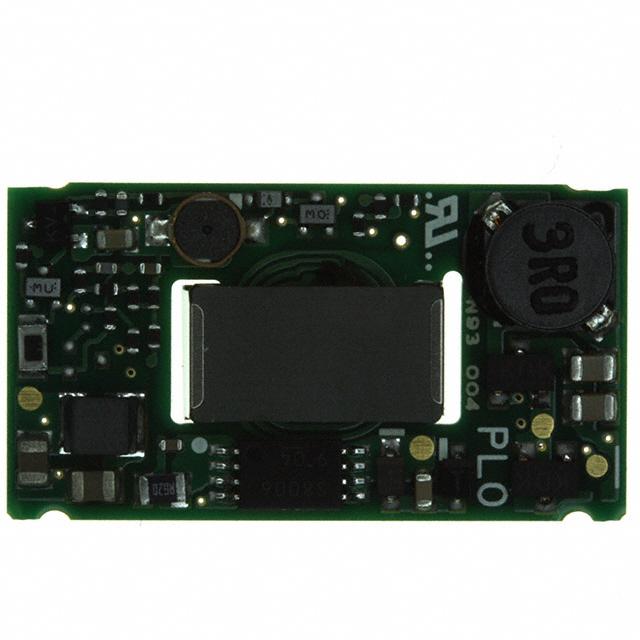
4 . Appearance, Dimensions
Objective Products
MPD5D01*S (*:3・4・6・7・8)
7
e
P⑤⑥
1
e = 2.54
2.22
Marking of No.1 pin
e
5
14.6
①②③④
e
6
e
4
2
3
Enlarged Lead Pin
(27.0)
2
Coplanarity 0.15Max.
3
[Unit:mm]
4
Tolerance
φ1.50
+0.20
1.60 -0.10
φ1.20
(1.45)
25.5
(4.4 max after solder Mount)
4.7max
26.8
Solder banking in Oblique
lined area.
5
6
1
7
Note:
1. This datasheet is downloaded from the website of Murata Manufacturing co., ltd. Therefore, it’ s specifications are subject to change or our
products in it may be discontinued without advance notice. Please check with our sales representatives or product engineers before ordering.
2. This datasheet has only typical specifications because there is no space for detailed specifications. Therefore, please approve our product
specifications or transact the approval sheet for product specifications before ordering.
2010.5.7
�MPD5D01*S Specification
2
(1) Product Number Code P**
Refer to table 1
(2) MFG ID
(3) Lot No.
①②③④⑤⑥
①Production factory Mark
②Production Year
③Production Month(1,2,3,…9,O,N,D)
④Product Modification Number (No Marking Now)
⑤⑥Last two letters of Product Number Code P**
Marking
Tabel1
Code
Product Number Code
Vout
Product Number
PLP
5.0V
MPD5D018S
PLO
3.3V
MPD5D017S
PMU
2.5V
MPD5D016S
PMS
1.8V
MPD5D014S
PMR
1.5V
MPD5D013S
5 . Pin Number and Function
Pin No.
Symbol
+Vout
1
2
-Vout
3
ALM
4
RC
5
PO
6
+Vin
7
-Vin
Function
(+)Output
(-)Output
Alarm output to stop all in abnormality.
Remote ON/OFF
Parallel operation.
(+)Input
(-)Input
6. Block Diagram
6.1 Entire Product
+Vout
+Vin
DRIVE
-Vout
7
5
4
3
1
DRIVE
Filter
6
2
-Vin
PO
RC
Controller
ALM
Note:
1. This datasheet is downloaded from the website of Murata Manufacturing co., ltd. Therefore, it’ s specifications are subject to change or our
products in it may be discontinued without advance notice. Please check with our sales representatives or product engineers before ordering.
2. This datasheet has only typical specifications because there is no space for detailed specifications. Therefore, please approve our product
specifications or transact the approval sheet for product specifications before ordering.
2010.5.7
�MPD5D01*S Specification
3
7. Environmental Conditions
7 .1 Operating Temperature Range
7 .2 Operating Humidity Range
7 .3 Storage Temperature Range
7 .4 Storage Humidity Range
-40°C ~ +85°C (Natural Air Convection : 0.2m/s with Vin=36 to 60V)
20% ~ 85% (No water condenses.)
-45°C ~ +90°C
10% ~ 95%( No water condenses.)
8. Absolute Rating
Item
Unit
Absolute Rating
V
0
Continuous
V
75
200µs
V
90
V
8
mA
10
Minimum Input Voltage
Maximum Input Voltage
ALM Applied Voltage
RC Applied Voltage
Time
PO Applied Voltage
Maximum ALM Sink Current
Remarks
Slew rate 42V/10µs
No voltage, no matter how instantaneous, shall be applied beyond the absolute maximum voltage rating to
this product.If you apply any voltage over this limit the product characteristics will deteriorate or the product
itself will be destroyed. Even though it may continue operating for a while after the over-voltage event, its life
will likely be shortened significantly.Reliability and life of the module may degrade similarly if the
maximum operating voltage rating is continuously exceeded.This product is designed to operate within
the maximum operating voltage rating specification.
9. Characteristics
9 .1 Electrical Characteristics (Ta=25°C)
9 .1 .1 General Characteristics
Unless otherwise specified, (Ta= -40 to +85°C with Natural Air Convection 0.2m/s)
Value
Item
Condition
Symbol
Min.
Typ.
Max.
Unit
Natural Air Convection Min 0.2m/s
36
48
60
Forced Air Convection Min 0.5m/s
60
-
75
Vin=increasing
32
-
36
V
Input Voltage difference
of Turn-on and Turn-off
PO pin : Open or Connected to PO
pin of other DC-DC Converters
2.0
-
-
V
Galvanic Isolation Voltage
Input time : 1 minute
1500
-
-
Vdc
Input Voltage Range
Turn-on Input Voltage
Item
Standard
Noise (Radiation, Conduction)
In accordance with VCCI Class A
Safety Standard
V
Vin
Note
Recognized UL60950(UL/C-UL),
Complied IEC 60950
UL file No.E190503
CE Marking
CE Mark is shown on a package box.
Note:
1. This datasheet is downloaded from the website of Murata Manufacturing co., ltd. Therefore, it’ s specifications are subject to change or our
products in it may be discontinued without advance notice. Please check with our sales representatives or product engineers before ordering.
2. This datasheet has only typical specifications because there is no space for detailed specifications. Therefore, please approve our product
specifications or transact the approval sheet for product specifications before ordering.
2010.5.7
�MPD5D01*S Specification
4
9 .1 .2 .1 Specific Characteristics
(Ta= -40 to +85°C with Natural Air Convection 0.2m/s ; Vin=36 to 60V or with Forced Air Convection 0.5m/s; Vin=60 to 75V)
Part Number
MPD5D013S
Value
Item
Symbol
Nominal Output Voltage
Vo
Output Voltage Variation
Δregtot
Output Current
Io
Efficiency
η
Ripple Voltage & Noise
Vr
Over Current Protection
Iocp
Over Voltage Protection
Vovp
Low Voltage Protection
Vlvp
Condition
Vin=36 to 75V, Io=0 to 0.8A
Ta=-40 to +85°C
Natural Air Convection 0.2m/s(Vin=36∼60V)
Forced Air Convection 0.5m/s(Vin=60∼75V)
Unit
Min.
Typ.
Max.
-
1.5
-
V
+5
%
-3
0
-
0.8
A
at rated Vin, Io, Ta=25°C
-
70
-
%
Refer to Test Circuit
-
-
50
mVpp
0.82
-
1.68
A
1.8
-
2.25
V
-
-
1.35
V
Output halts in latch-up mode after mask time
0.5msec (typ) to avoid malfunction by noise
and transient change.
Input turn off and on to reset.
Output halts in latch-up mode after mask time
500msec (typ) to avoid malfunction by noise
and transient change.
Input turn off and on to reset.
9 .1 .2 .2 Specific Characteristics
(Ta= -40 to +85°C with Natural Air Convection 0.2m/s ; Vin=36 to 60V or with Forced Air Convection 0.5m/s; Vin=60 to 75V)
Part Number
MPD5D014S
Value
Item
Symbol
Nominal Output Voltage
Vo
Output Voltage Variation
Δregtot
Output Current
Io
Efficiency
η
Ripple Voltage & Noise
Vr
Over Current Protection
Iocp
Over Voltage Protection
Vovp
Low Voltage Protection
Vlvp
Condition
Vin=36 to 75V, Io=0 to 1.0A
Ta=-40 to +85°C
Natural Air Convection 0.2m/s(Vin=36∼60V)
Forced Air Convection 0.5m/s(Vin=60∼75V)
Unit
Min.
Typ.
Max.
-
1.8
-
V
+5
%
-3
0
-
1.0
A
at rated Vin, Io, Ta=25℃
-
75
-
%
Refer to Test Circuit
-
-
50
mVpp
1.03
-
2.00
A
2.16
-
2.70
V
-
-
1.62
V
Output halts in latch-up mode after mask time
0.5msec (typ) to avoid malfunction by noise
and transient change.
Input turn off and on to reset.
Output halts in latch-up mode after mask time
500msec (typ) to avoid malfunction by noise
and transient change.
Input turn off and on to reset.
!
Caution
The above electrical characteristics are guaranteed in the condition that the impedance of the input power supply
is sufficiently low as shown in clause 10.
Connecting an input inductance or using an input power supply with output inductance may cause an
unstable operation of this product. Please check the proper operation of this product with the peripheral circuits
on your product.
Note:
1. This datasheet is downloaded from the website of Murata Manufacturing co., ltd. Therefore, it’ s specifications are subject to change or our
products in it may be discontinued without advance notice. Please check with our sales representatives or product engineers before ordering.
2. This datasheet has only typical specifications because there is no space for detailed specifications. Therefore, please approve our product
specifications or transact the approval sheet for product specifications before ordering.
2010.5.7
�MPD5D01*S Specification
5
9 .1 .2. 3
Specific Characteristics
(Ta= -40 to +85°C with Natural Air Convection 0.2m/s ; Vin=36 to 60V or with Forced Air Convection 0.5m/s; Vin=60 to 75V)
Part Number
MPD5D016S
Value
Item
Symbol
Nominal Output Voltage
Vo
Output Voltage Variation
Δregtot
Output Current
Condition
Unit
Min.
Typ.
Max.
-
2.5
-
V
+5
%
Vin=36 to 75V, Io=0 to 1.2A
Ta=-40 to +85°C
-3
Io
Natural Air Convection 0.2m/s(Vin=36∼60V)
Forced Air Convection 0.5m/s(Vin=60∼75V)
0
-
1.2
A
Efficiency
η
at rated Vin, Io, Ta=25°C
-
80
-
%
Ripple Voltage & Noise
Vr
Refer to Test Circuit
-
-
50
mVpp
Over Current Protection
Iocp
1.23
-
2.34
A
3.0
-
3.75
V
-
-
2.25
V
Over Voltage Protection
Vovp
Low Voltage Protection
Vlvp
9 .1 .2. 4
Output halts in latch-up mode after mask time
0.5msec (typ) to avoid malfunction by noise
and transient change.
Input turn off and on to reset.
Output halts in latch-up mode after mask time
500msec (typ) to avoid malfunction by noise
and transient change.
Input turn off and on to reset.
Specific Characteristics
(Ta= -40 to +85°C with Natural Air Convection 0.2m/s ; Vin=36 to 60V or with Forced Air Convection 0.5m/s; Vin=60 to 75V)
Part Number
MPD7D108S
Value
Item
Nominal Output Voltage
Symbol
Condition
Vo
Output Voltage Variation
Δregtot
Output Current
Io
Efficiency
η
Ripple Voltage & Noise
Vr
Over Current Protection
Iocp
Over Voltage Protection
Vovp
Low Voltage Protection
Vlvp
Vin=36 to 75V, Io=0 to 1.5A
Ta=-40 to +85°C
Natural Air Convection 0.2m/s(Vin=36∼60V)
Forced Air Convection 0.5m/s(Vin=60∼75V)
Unit
Min.
Typ.
Max.
-
3.3
-
V
+5
%
-3
0
-
1.5
A
at rated Vin, Io, Ta=25°C
-
84
-
%
Refer to Test Circuit
-
-
50
mVpp
1.54
-
2.65
A
3.96
-
4.62
V
-
-
2.97
V
Output halts in latch-up mode after mask time
0.5msec (typ) to avoid malfunction by noise
and transient change.
Input turn off and on to reset.
Output halts in latch-up mode after mask time
500msec (typ) to avoid malfunction by noise
and transient change.
Input turn off and on to reset.
!
Caution
The above electrical characteristics are guaranteed in the condition that the impedance of the input power supply
is sufficiently low as shown in clause 10.
Connecting an input inductance or using an input power supply with output inductance may cause an
unstable operation of this product. Please check the proper operation of this product with the peripheral
circuits on your product.
Note:
1. This datasheet is downloaded from the website of Murata Manufacturing co., ltd. Therefore, it’ s specifications are subject to change or our
products in it may be discontinued without advance notice. Please check with our sales representatives or product engineers before ordering.
2. This datasheet has only typical specifications because there is no space for detailed specifications. Therefore, please approve our product
specifications or transact the approval sheet for product specifications before ordering.
2010.5.7
�MPD5D01*S Specification
6
9 .1 .2. 5
Specific Characteristics
(Ta= -40 to +85°C with Natural Air Convection 0.2m/s ; Vin=36 to 60V or with Forced Air Convection 0.5m/s; Vin=60 to 75V)
Part Number
MPD7D108S
Value
Item
Symbol
Nominal Output Voltage
Vo
Output Voltage Variation
Δregtot
Output Current
Io
Efficiency
η
Ripple Voltage & Noise
Vr
Over Current Protection
Iocp
Over Voltage Protection
Vovp
Low Voltage Protection
Vlvp
!
Condition
Vin=36 to 75V, Io=0 to 1.0A
Ta=-40 to +85°C
Natural Air Convection 0.2m/s(Vin=36∼60V)
Forced Air Convection 0.5m/s(Vin=60∼75V)
Unit
Min.
Typ.
Max.
-
5.0
-
V
+5
%
-3
0
-
1.0
A
at rated Vin, Io, Ta=25°C
-
85
-
%
Refer to Test Circuit
-
-
50
mVpp
1.03
-
1.70
A
6.0
-
7.0
V
-
-
4.5
V
Output halts in latch-up mode after mask time
0.5msec (typ) to avoid malfunction by noise
and transient change.
Input turn off and on to reset.
Output halts in latch-up mode after mask time
500msec (typ) to avoid malfunction by noise
and transient change.
Input turn off and on to reset.
Caution
The above electrical characteristics are guaranteed in the condition that the impedance of the input power
supply is sufficiently low as shown in clause 10.
Connecting an input inductance or using an input power supply with output inductance may cause an
unstable operation of this product. Please check the proper operation of this product with the peripheral
circuits on your product.
9. 2 Operation information
9. 2. 1 Reset Condition
In order to reset all function, the input Voltage is set under 5V for Min.1 second.
Input Voltage 36-75V
Reset Condition
Max. 5V
Min. 1 second
9. 2. 2 Over Voltage Protection
Output halts in latch-up mode after 0.5msec(typ) mask time while Output Voltage is over the value of
over voltage protection specified in 9.1. clause with failure of controller circuit.
Output will re-start after input turns off for Min. 1 second with input voltage less than 5V.
Output voltage might exceed the point at over voltage protection under the specific condition of transient
change of input voltage or output load, in this condition over voltage protection wait its start until the
mask time.
It is recommended to evaluate your appliance installed with DC-DC converter.
Input Voltage 36-75V
Re-start Condition
Max. 5V
Min. 1 second
Note:
1. This datasheet is downloaded from the website of Murata Manufacturing co., ltd. Therefore, it’ s specifications are subject to change or our
products in it may be discontinued without advance notice. Please check with our sales representatives or product engineers before ordering.
2. This datasheet has only typical specifications because there is no space for detailed specifications. Therefore, please approve our product
specifications or transact the approval sheet for product specifications before ordering.
2010.5.7
�MPD5D01*S Specification
7
9. 2. 3 Low Voltage Protection
Output halts in latch-up mode after 500msec(typ) mask time while output voltage is below the value of
low voltage protection specified in 9.1.clause with failure of controller circuit or over load condition.
Output will re-start after input turns off for Min.1 second with input voltage less than 5V.
Input Voltage 36-75V
Re-start Condition
Max. 5V
Min. 1 second
9. 2. 4 Remote On/Off Control
Start and halt is possible with a control signal.
While the control signal stops output from DC-DC Converter, alarm output does not send any signal.
Start : RC is open or connected to-Vin.
Halt : RC is connected to +Vin.
9. 2. 5 Alarm Output
ALM pin is down to the same voltage level of-Vin pin and sends an alarm signal. (open-drain output)
Sink current in ALM pin is Max.20mA.
It is possible to halt all of the connected DC-DC Converters when any one is halted with over voltage
protection or low voltage protection, with connecting all ALM pins for the application of multiple
operation with plural DC-DC converters.
The maximum number connecting DC-DC Converters is (one this product is counted as two) 20pcs
for the purpose of halting all DC-DC Converters connected with ALM pin each other. When the other
series are connected to this series for multiple operation, please count one this product as two.
Also please contact us when more than 20pcs.
9. 2. 6 Synchronous Turn-on/off
ALM pin is down to the same voltage level of-Vin pin and sends an alarm signal. (open-drain output)
Sink current in ALM pin is Max.10mA.
It is possible to halt all of the connected DC-DC Converters when any one is halted with over voltage
protection or low voltage protection, with connecting all ALM pins for the application of parallel/
multiple operation with plural DC-DC Converters.
The maximum number connecting DC-DC Converters is 10pcs for the purpose of halting all DC-DC
Converters connected with ALM pin each other.
Please contact us when more than 10pcs.
9. 3 Reliability
9. 3. 1 Reliability Test Items
Item
Test Condition
+40±2°C 90 to 95%RH 100 hours
Humidity
Then RT(25°C) for 4 hours (JIS-C-0022)
--40±3°C (30minutes)
↓
Room temp.(5 to 10 minutes)
↓
Temp. Cycle
+85±3°C (30minutes)
↓
Room temp.(5 to 10 minutes)
Criteria
No damage in appearance
and no deviation of elect
before and after the test.
Repeat 5time of the above
Mechanical
Vibration
10 to 55Hz, max. 1.5mm amplitude, 1 hour for
each of X, Y, Z directions.
Mechanical Shock
20G, 1 time for each of X, Y, Z directions.
Note:
1. This datasheet is downloaded from the website of Murata Manufacturing co., ltd. Therefore, it’ s specifications are subject to change or our
products in it may be discontinued without advance notice. Please check with our sales representatives or product engineers before ordering.
2. This datasheet has only typical specifications because there is no space for detailed specifications. Therefore, please approve our product
specifications or transact the approval sheet for product specifications before ordering.
2010.5.7
�MPD5D01*S Specification
8
9. 3. 2 Soldering Heat Resistance
Immerse the part of lead where it is to be soldered on a motherboard in a solder bath of 260+/-5°C for
3+/-0.5s.
Then tested products are left for 2 hours.
There is no damage in appearance and no deviation from electrical characteristics in clause 9.
9. 3. 3 Lead Pin Strength
Strain a lead pin by gradual-increasingly 5.0N along axial direction; withstand for 5s.
No damage on a lead pin.
9. 3. 4 Solderability of Leads
The lead pins will be immersed in the Isopropyl Alcohol (JIS K 1522) with Rosin (JIS K5902) solution (the
concentration of Rosin will be allowed 10wt% to 35wt%, and normally approx. 25wt% will be used without
any specific requirement.).
Then the lead pins will be immersed in the solder H63A (JIS Z 3282) solution at the temperature of 230°C
+/-5°C for 3+/-0.5seconds, and pulled up completely.
The solder will adhere to over 75% of immersed area.
10. Test Circuit
In the following test circuit, the measured values should meet those of clause 9.
10.1 General Measure Circuit
Oscilloscope
A
A1
V
Ein
Input
capacitor
(Note)
RL Load
V1
Isolated DC-DC
Converter
Stabilized DC
power supply
A
V
Multimater
(Note) Please connect 10µF input capacitor for the test condition considered input voltage chattering.
10.1.1 Output Ripple & Noise
Coaxial cable : 1.5D-2V, (JISC3501), Length is 1.5m
+I N
+O UT
Ein
-I N
-O UT
C1 =10μ F
(Ceramic Capacitor)
Oscilloscope
f BW : 500M Hz
with Feed thru-Termination
Capacitor : 10µF
Input
Output
(Connect to tip of output pins.)
Keisokugiken
TR C- 50F
Equivalent
circuit
R: 50Ω
C:0.01μ F
Coaxial cable
A: Output Ripple Voltage&Noise
B: Output Ripple Voltage
B
A
C: Switching Period
C
Note:
1. This datasheet is downloaded from the website of Murata Manufacturing co., ltd. Therefore, it’ s specifications are subject to change or our
products in it may be discontinued without advance notice. Please check with our sales representatives or product engineers before ordering.
2. This datasheet has only typical specifications because there is no space for detailed specifications. Therefore, please approve our product
specifications or transact the approval sheet for product specifications before ordering.
2010.5.7
�MPD5D01*S Specification
9
27.9
A-A' 断面図
A-A' Cross Section
312.8
322.6
A
B
B'
P2×9=261.0
P2=29.0
(18.1)
30.8
A'
4.9
C5
11. Packaging Information
11.1 Tray Dimensions
DC-DC Converters are put in the trays. (See Fig.1)
P1=40.0
8.0
P1×2=80.0
135.9
4.9
126.1
(9.2)
単位:mm
一般公差:±1.5
Unit : mm
General Tolerance
B-B' 断面図
B-B' Cross Section
Fig.1
Note:
1. This datasheet is downloaded from the website of Murata Manufacturing co., ltd. Therefore, it’ s specifications are subject to change or our
products in it may be discontinued without advance notice. Please check with our sales representatives or product engineers before ordering.
2. This datasheet has only typical specifications because there is no space for detailed specifications. Therefore, please approve our product
specifications or transact the approval sheet for product specifications before ordering.
2010.5.7
�MPD5D01*S Specification
10
11.2 Contained pieces of products per corrugated box.
Maximum Contained products pieces 210 pcs/corrugated box.
Further plural sheets of corrugated cardboard are placed on the top of the dummy tray according to number
of contained trays in order to full up the space in a corrugated box.
11.3 Packaging Form
Trays with products are lidded and packed in a corrugated box. (See Fig.2)
Corrugated cardboard
Dummy tray
Containning products
Tray
6 tray max.
Corrugated cardboard
( 330)
( 68)
MURATA PRODUCTS
( 155)
Corrugated box
Lebel
Dimension [unit : mm]of
Corrugated box is reference only.
Fig.2
Marking on the box
1. MURATA Parts Number
2. Quantity
3. Inspection No.
4. CE Mark
12. Production factory
Wakura Murata Mfg. Co., Ltd.
Kanazu Murata Mfg.Co.,Ltd.
Komatsu Murata Mfg.Co.,Ltd.
!
Note
1 . Be sure to provide an appropriate fail-safe function on your product to prevent secondary damage
that may be caused by the functional trouble or the failure of this product.
2 . Please contact us before using this product for the applications listed below which require especially
high reliability for the prevention of defects and failure , which might directly cause damage to the third party’s
life, body or property.
①Aircraft equipment
②Aerospace equipment
③Undersea equipment
④Power plant control equipment
⑤Medical equipment
⑥Transportation equipment (vehicles, trains, ships, etc.)
⑦Traffic signal equipment
⑧Disaster prevention /crime prevention equipment
⑨Any other application of similar complexity and/or reliability requirements to the applications listed above.
Note:
1. This datasheet is downloaded from the website of Murata Manufacturing co., ltd. Therefore, it’ s specifications are subject to change or our
products in it may be discontinued without advance notice. Please check with our sales representatives or product engineers before ordering.
2. This datasheet has only typical specifications because there is no space for detailed specifications. Therefore, please approve our product
specifications or transact the approval sheet for product specifications before ordering.
2010.5.7
�MPD5D01*S Specification
11
13 . Notice
13. 1 Soldering
13. 1. 1 Flux
Please solder this product with Rosin Flux, which contains of 0.2wt%. or less chlorine.
Please do not use high activity acid flux or water soluble flux because they may erode metal or glass
portion of this product and may cause defectiveness or deterioration of this product.
13. 1. 2 Solder
Please use the solder H60, H63(JIS Z3282)or the equivalent type.
Please use the solder paste of equivalent type H60, H63.
13. 1. 3 Recommended Soldering Conditions
Reflow Solder
Reflow Soldering Profiles
JEDEC IPC/JEDEC J-STD-020D
Table 5-2 Classification Reflow Profiles
Pb-Free Assembly Large Body
Profile details
Soldering temperature
Soldering time
Heating time
Preheating time
Programming rate
Descending rate
Total soldering time
Time
:245 ºC +0/-5
:30 seconds,240∼245 ºC
:60∼150 seconds,217 ºC or more.
:60∼120seconds,150∼200 ºC
:3 ºC /sec.Max.,217∼245 ºC
:6 ºC /sec.Max.
:8 minutes Max.,25∼245 ºC
:Maximum 2times
※The solder used to this product is melted in reflow process.
Therefore do not add excessive vibration and strong air below to this product during reflow.
Please take out the products from a reflow furnace after the product temperature is cooled down
thoroughly.
When this product is mounted on backside of a motherboard like the below figure, the measurement
except soldering should be taken with dipping thermal setting resin around a Transformer Metal
Cover to prevent this product from dropping.
Mother board
Isolated DC-DC Converter
[Note] The product has a solder banking on the top of a lead pin.
Coplanarity is required with melting the solder banking during reflow process.
Therefore please confirm in advance that the solder banking is melted enough.
13. 2 Cleaning
13. 2. 1 Please clean this product to remove flux by using dip, boil, and vapor methods in isopropyl alcohol for
up to 5 minutes.
Please inform us if you are to use aqueous or semi –aqueous cleaning or other methods.
Do not use ultrasonic cleaning because semiconductor device on this product maybe damaged
by resonance.
13. 2. 2 After cleaning, please dry this product thoroughly.
If you touch the wet product, marking maybe erased or blurred.
Do not measure electrical characteristics, until this product gets dried enough.
13. 2. 3 If you don’t clean this product with no-cleaning type flux, you must confirm fully in advance the reliability
of this product.
Note:
1. This datasheet is downloaded from the website of Murata Manufacturing co., ltd. Therefore, it’ s specifications are subject to change or our
products in it may be discontinued without advance notice. Please check with our sales representatives or product engineers before ordering.
2. This datasheet has only typical specifications because there is no space for detailed specifications. Therefore, please approve our product
specifications or transact the approval sheet for product specifications before ordering.
2010.5.7
�MPD5D01*S Specification
12
13. 3 Storage
13. 3. 1 Please store the products in room where the temperature/humidity is stable and direct sunlight cannot
come in, and use the products within 6 months after delivery.
Please avoid damp and heat or such places where the temperature greatly changes, as water may
condense on this product, and the quality of characteristics may be reduced, and/or be the solderability
may be degraded.
If this product needs to be stored for a long time (more than 1 year), this product may be degraded
in solderability and/or corroded. Please test the solderability of this product regularly.
13. 3. 2 Please do not store this product in the conditions such as a dusty place, a place exposed directly to sea
breeze, or in an atmosphere containing corrosive gas (Cl2, NH3, SO2, NOX and so on).
13. 4 Operational Environment and Operational Conditions
13. 4. 1 Operational Environment
This product is not water-, chemical- or corrosion-proof.
In order to prevent leakage of electricity and abnormal temperature rise of this product, do not use this
product in the following conditions:
(1) in an atmosphere containing corrosive gas (Cl2, NH3, SO2, NOX and so on)
(2) in a dusty place
(3) in a place exposed to direct sunlight
(4) in such a place where water splashes or in such a humid place where water condenses
(5) in a place exposed to sea breeze
(6) in any other places similar to the above
13. 4. 2 Operational Conditions
Please use this product within specified values (power supply, temperature, input, output, load condition,
and so on).
If not used within the specified values, defectiveness and deterioration of this product may be caused.
Even if this product can endure the condition for short time, it may cause degradation of reliability.
It is recommended that a fuse is inserted in input line (Vin) to secure safety in any abnormality such as
internal circuit of Isolated DC-DC Converter broken down.
Also please take care that the external voltage over output voltage of DC-DC Converter does not applies
to output of this Isolated DC-DC Converter.
13. 4. 3 Note prior to use
Defectiveness and reliability degradation may be caused if high static electricity, over rated voltage or
reverse voltage are applied to this product. Please be sure to avoid the followings:
(1) over rating power supply, reverse power supply or inadequate connection of 0 V(DC)line
(2) electrostatic discharge from production line and/or operator
(3) electrified product from electrostatic induction
Please avoid an excessive mechanical shock.
If this product is dropped on the floor, etc., a crack to the core of inductors and monolithic ceramic
capacitors may occur.
Please handle with care to avoid a strong shock to this product.
Do not give excessive mechanical stress to the product with your handling.
Please control to bend in a maximum of 0.2mm in your application.
13. 5 Transportation
When transporting this product, please pack it in order to avoid damage by mechanical vibration or
mechanical shock, and please give instructions and set guidelines to the carriers to prevent rough handling.
When transporting this product overseas (in particular, by sea), bad environment of transportation may be
expected, therefore please pack this product considering mechanical strength, vibration-resistance and
humidity-resistance.
The packaging designed for domestic sales may not suitable for overseas transportation.
Please contact us if this product with domestic packing is transported overseas.
14. ! Note
1. Murata recommends that customers ensure that the evaluation and testing of these devices are completed with
this product actually assembled on their product.
2. All the items and parameters in this product specification have been prescribed on the premise that Murata’s
product is used for the purpose, under the condition and in the environment mutually agreed upon.
This document is for reference only and subject to revision without prior of subsequent notice.
Please contact Murata for latest documentation.
Note:
1. This datasheet is downloaded from the website of Murata Manufacturing co., ltd. Therefore, it’ s specifications are subject to change or our
products in it may be discontinued without advance notice. Please check with our sales representatives or product engineers before ordering.
2. This datasheet has only typical specifications because there is no space for detailed specifications. Therefore, please approve our product
specifications or transact the approval sheet for product specifications before ordering.
2010.5.7
�


 工商网监
湘ICP备2023018690号
工商网监
湘ICP备2023018690号
