RBC-12/17-D48 Series
www.murata-ps.com
Quarter Brick, Regulated Bus Converters
Output (V)
Current (A)
Nominal Input (V)
12
17
48
Optimized for distributed power Regulated Intermediate Bus Architectures (RIBA), the RBC DC/DC bus converter series offer regulated
outputs (±1.5%) in an industry-standard quarter brick open frame
package.
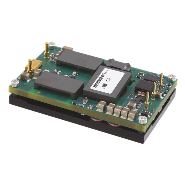
Typical unit
FEATURES
PRODUCT OVERVIEW
Up to 210 Watts total output power
The present trend in distributed power architectures (DPA) requires both high efficiency and some
regulation of the output voltage to reduce the risk
of under voltage dropout. Earlier unregulated bus
converters were simply ratiometric “DC transformers.” The fully isolated (2250Vdc) RBC series accept
a wide range 36 to 75 Volt DC input (48V nominal)
and convert it to an output of 12Vdc. This output
then drives point-of-load (PoL) converters such as
our Okami, LSN, LEN, LSM or LQN series which
feature precise load regulation. Applications include
48V-powered datacom and telecom installations,
base stations, cellular telephone repeaters and
embedded systems. Low overall height of 0.42"
(10.7 mm) fits tight card cages.
Up to 93% ultra-high efficiency @ full load
48V Input ( up to 36-75V range)
12V/17A Output for Regulated Intermediate Bus
Architectures (RIBA) with POL converters
Synchronous-rectifier topology
225kHz fixed switching frequency
Fully isolated, 2250Vdc (BASIC)
2.3" x 1.45" x 0.42" quarter brick
Stable no-load condition
Thermal shutdown
Fully I/O protected
The RBC’s synchronous-rectifier topology and fixed
frequency operation means excellent efficiencies.
“No fan” or zero airflow applications may use the
optional base plate for cold surface mounting or
natural-convection heatsinks.
A wealth of electronic protection features include
input undervoltage (UV) lockout, output current limit,
short circuit hiccup, overtemperature shutdown and
output overvoltage. Available options include positive or negative logic remote On/Off control and the
baseplate. Assembled using ISO-certified automated
surface-mount techniques, the RBC series includes
all UL and IEC emissions, safety and flammability
certifications.
Certified to UL/IEC/EN 60950-1 and CSA C22.2
No.60950-1-07, 2nd edition
+VIN
(1)
+VOUT
(8)
–VIN
(3)
GATE
DRIVE
–VOUT
(4)
SWITCHING
CONTROLLER
VOLTAGE
SENSE
REMOTE
ON/OFF
(2)
HICCUP
CURRENT
SENSE
OV, UV, OT
SHUTDOWN
Typical topology is shown.
Figure 1. Simplified Block Diagram
For full details go to
www.murata-ps.com/rohs
www.murata-ps.com/support
MDC_RBC-12/17-D48.C02 Page 1 of 10
�RBC-12/17-D48 Series
Quarter Brick, Regulated Bus Converters
PERFORMANCE SPECIFICATIONS SUMMARY AND ORDERING GUIDE
Root Model ➀
RBC-12/17-D48N-C
V
IOUT
(Max.)
A
Typ.
Max.
12
17
50
75
VOUT
Regulation
(Max.)
Line
Load
R/N (mV pk-pk)
±0.65%
±1.5%
VIN
(Nom.)
V
48
V
Iin, no
load
mA
Iin, full
load
A
Min.
Typ.
Case
Pinout
36-75
165
4.59
90.5%
92.5%
C49
P65
Range
Efficiency
Package
➀ Please refer to the part number structure for complete model numbers
PART NUMBER STRUCTURE
R BC - 12 / 17 - D48 N B - C
RoHS-6 hazardous substance compliant
(does not claim EU RoHS exemption 7b–lead in solder)
Regulated
Bus Converter
Nominal Output Voltage:
12 Volts
Optional Baseplate,
special order
Note:
Some model number combinations may not be
available. Contact Murata Power Solutions for
ordering assistance.
Maximum Rated Output:
Current in Amps
Input Voltage Range:
D48 = 36 to 75 Volts
(48V nominal)
CAUTION – This converter is not internally fused. To avoid danger to persons or
equipment and to retain safety certification, the user must connect an external
fast-blow input fuse as listed in the specifications. Be sure that the PC board
pad area and etch size are adequate to provide enough current so that the fuse
will blow with an overload.
Optional:
On/Off Control
N = negative logic , standard
P = positive logic, optional
allow the instantaneous input voltage to go below the minimum voltage at all
times. Even if this voltage depression is very brief, this may interfere with the
on-board controller and possibly cause a failed start.
Start-Up Considerations
Use a moderate size capacitor very close to the input terminals. You may need
two parallel capacitors. A larger electrolytic or tantalum cap supplies the surge
current and a smaller parallel low-ESR ceramic cap gives low AC impedance.
When power is first applied to the DC/DC converter, there is some risk of start
up difficulties if you do not have both low AC and DC impedance and adequate
regulation of the input source. Make sure that your source supply does not
Remember that the input current is carried both by the wiring and the ground
plane return. Make sure the ground plane uses adequate thickness copper. Run
additional bus wire if necessary.
www.murata-ps.com/support
MDC_RBC-12/17-D48.C02 Page 2 of 10
�RBC-12/17-D48 Series
Quarter Brick, Regulated Bus Converters
Performance/Functional Specifications
Typical at TA = +25°C under nominal input voltage and full-load conditions unless noted.
Refer to required airflow and Derating curves for thermal specifications. [1]
Input
Electronic Thermal Shutdown
+125°C min.
Operating Temperature Range
(With Derating)
-40ºC to +85ºC, See Derating curves
Input Voltage Range
36-75 Volts
Storage Temperature Range
–55 to +125°C
Recommended External Fuse
20 Amp fast blow
Flammability
UL94V-0
Start-up Threshold
35V
Relative Humidity
To 85% / +85°C
Undervoltage shutdown
33.5V
Safety Compliance
Overvoltage shutdown
None [note 12]
UL60950-1, CSA-C22.2 No.60950-1,
IEC/EN60950-1
Input Current, nominal
See ording guide
Electromagnetic Interference
conducted or radiated
EN55022/CISPR22
(may require external filters)
Input Current, VIN = VMIN
6.00A
Input Current, shut-down mode
6.5mA max.
Physical
2
0.05A -seconds
Inrush Transient
Reflected Ripple Current [2]
15mAp-p
Internal Filter Type
L-C
Reverse Polarity Protection
None (see note 11), install external fuse
Remote On/Off Control [5]
Positive Logic
Current
Output
Total Output Power [3]
210W max. [15]
Setpoint Accuracy (50% load)
±3% of VNOMINAL
Extreme Accuracy [14]
11.4V min. to 12.6V max.
Output Current [7]
See ordering guide
Minimum Load
No minimum load
Ripple and Noise (20MHz bandwidth)
See ordering guide
Line and Load Regulation [10]
See ordering guide
Efficiency
See ordering guide
Isolation Voltage (Input/output)
(Input to baseplate)
(Baseplate to output)
2250Vdc min.
1500Vdc min.
1500Vdc min.
Isolation Resistance
100M
Isolation Capacitance
1500pF
Isolation Safety Rating
Basic
Copper alloy with gold plate over nickel underplate
Weight
1 ounce (28.4 grams)
Absolute Maximum Ratings
On = Open or +3.5 to +13.5 V.
Off = Gnd. Pin or 0 to +1V.
On = Gnd. Pin or 0 to +1V.
Off = Pin open or +3.5V to +13.5V.
2mA max.
Negative Logic
Pin Material
Input Voltage:
Continuous
Transient (100msec max.)
75 Volts
100 Volts
Input Reverse-Polarity Protection
None, see notes. Install external fuse.
Output Current
Current limited. Devices can
withstand an indefinite output short
circuit without damage.
Storage Temperature
–55 to +125°C
Lead Temperature (soldering, 10 sec.)
+280°C
These are stress ratings. Exposure of devices to any of these conditions may adversely
affect long-term reliability. Proper operation under conditions other than those listed in
the Performance/Functional Specifications Table is not implied.
(1)
All models are tested and specified with external 1 || 10uF ceramic/tantalum output capacitors and external
22uF input capacitor. All capacitors are low ESR types. These capacitors are necessary to accommodate our
test equipment and may not be required to achieve specified performance in your applications. All models are
stable and regulate within spec under no-load conditions.
(2)
Input Ripple Current is tested and specified over a 5 Hz to 20 MHz bandwidth. Input filtering is CIN = 33μF/100V
tantalum, CBUS = 220μF/100V electrolytic, LBUS = 12μH.
(3)
Note that Maximum Power Derating curves indicate an average current at nominal input voltage. At higher
temperatures and/or lower airflow, the DC/DC converter will tolerate brief full current outputs if the total RMS
current over time does not exceed the Derating curve. All Derating curves are presented at sea level altitude. Be
aware of reduced power dissipation with increasing density altitude.
(4)
Mean Time Before Failure is calculated using the Telcordia (Belcore) SR-332 Method 1, Case 3, ground fixed
conditions, TPCBOARD = +25°C, full output load, natural air convection.
(5)
Short Circuit Duration (+VOUT grounded) Continuous, no damage
The On/Off Control may be driven with external logic or by applying appropriate external voltages which are
referenced to Input Common. The On/Off Control Input should use either an open collector/open drain transistor
or logic gate which does not exceed +13.5V.
(6)
Short circuit shutdown begins when the output voltage degrades approximately 2% from the selected setting.
Overvoltage Protection
15Vdc max. via magnetic feedback
(7)
The outputs are not intended to sink appreciable reverse current.
Max. Capacitive Loading (resistive load)
10,000μF, low ESR 0.02 Ohms
(8)
Output noise may be further reduced by adding an external filter. See I/O Filtering and Noise Reduction.
Temperature Coefficient
±0.02% per °C
(9)
All models are fully operational and meet published specifications, including “cold start” at –40°C.
Current Limit Inception (98% of VOUT)
27A, after warm up
Short Circuit Current [6]
5 Amps
(hiccup autorestart – remove short for
recovery)
Dynamic Characteristics
General conditions for Specifications are +25°C, VIN = nominal, VOUT = nominal, full load.
(10) Regulation specifications describe the deviation as the line input voltage or output load current is varied from a
nominal midpoint value to either extreme.
Dynamic Load Response
(to within 3% of VOUT)
75μsec, 50-75-50% load step
100μsec, 25-75-25% load step
Start Up Time
(VIN to VOUT regulated)
(Remote On to Vout regulated)
(11) If reverse polarity is accidentally applied to the input, a body diode will become forward biased and will accept
considerable current. To ensure reverse input protection with full output load, always connect an external input
fuse in series with the +VIN input. Use approximately twice the full input current rating with nominal input
voltage.
60msec
60msec
(12) Input overvoltage shutdown on 48V input models is normally deleted in order to comply with certain telecom
reliability requirements. These requirements attempt continued operation despite significant input overvoltage.
Fixed Switching Frequency
225 ±25kHz
(13) Note that the converter may operate up to +110°C PCB temperature with the baseplate installed. However,
thermal self-protection occurs near +125°C and there is a temperature gradient from high power components.
Therefore, +100°C baseplate temperature is recommended to avoid thermal shutdown.
Environmental
Calculated MTBF [4]
1,247,727 hours
(14) “Extreme accuracy” refers to all combinations of line and load regulation, output current, initial setpoint
accuracy and temperature coefficient.
Operating Case Temperature [13]
+110°C max.
(15) Vo = (11.64V to 12.36V)
Power = (197.88W to 210.12W)
www.murata-ps.com/support
MDC_RBC-12/17-D48.C02 Page 3 of 10
�RBC-12/17-D48 Series
Quarter Brick, Regulated Bus Converters
MECHANICAL SPECIFICATIONS
58.4
2.30
47.24
1.860
M3 x 0.5-6H THREAD
X 0.15 DP TYP (4 PLS)
TOP VIEW
36.8
1.45
END VIEW
ALUMINUM
BASEPLATE
'B' OPTION
26.16
1.030
10.7
0.42
WITHOUT
BASEPLATE
12.7
0.50
WITH
BASEPLATE
SIDE VIEW
3.5
0.14
REF
SEATING PLANE
4.8
0.19
PIN LENGTH
ABOVE SEATING
PLANE
(SEE NOTE 1
ON SHEET 2)
0.060 0.002 [1.52 0.05]
2X AT PINS 4-5
3
4
36.8
1.45
REF
2
15.24
0.600
1
7.62
0.300
8
BOTTOM VIEW
2.000
DIMENSIONS ARE IN INCHES [mm]
TOLERANCES:
2 PLACE 0.02
3 PLACE 0.010
0.010 MIN
FROM SEATING
PLANE TO HIGHEST
COMPONENT
0.040 0.002 [1.02 0.05]
3X AT PINS 1-3
INPUT/OUTPUT CONNECTIONS
Pin
Function
1
+Input
2
Remote On/Off*
3
-Input
4
-Output
8
+Output
* The Remote On/Off can be
provided with either positive (P
suffix) or negative (N suffix) logic.
ANGLES: 1
COMPONENTS SHOWN ARE FOR REFERENCE ONLY
MATERIAL:
0.040 PINS: COPPER ALLOY
0.060 PINS: COPPER ALLOY
FINISH: (ALL PINS)
GOLD (5u"MIN) OVER NICKEL (50u" MIN)
Dimensions are in inches (mm shown for ref. only).
Third Angle Projection
Tolerances (unless otherwise specified):
.XX ± 0.02 (0.5)
.XXX ± 0.010 (0.25)
Angles ± 2˚
Components are shown for reference only.
www.murata-ps.com/support
MDC_RBC-12/17-D48.C02 Page 4 of 10
�RBC-12/17-D48 Series
Quarter Brick, Regulated Bus Converters
RECOMMENDED FOOTPRINT (VIEW THROUGH CONVERTER)
REF: DOSA STANDARD SPECIFICATION
FOR QUARTER BRICK DC/DC CONVERTERS
FINISHED HOLE SIZES
@ PINS 1-3
TOP VIEW
(PER IPC-D-275, LEVEL C)
0.048-0.062
CL
(PRI)
(SEC)
8
1
37.3
1.47
CL
2
4
3
7.6
0.300
7.6
0.300
CL
FINISHED HOLE SIZES
@ PINS 4 & 8
0.100MIN
@ 1-4, 8
FOR PIN
SHOULDERS
(PER IPC-D-275, LEVEL C)
25.4
1.00
0.070-0.084
50.8
2.000
58.9
2.32
IT IS RECOMMENDED THAT NO PARTS
BE PLACED BENEATH CONVERTER
(HATCHED AREA)
1. ALTERNATE PIN LENGTHS AVAILABLE
(CONTACT MURATA-PS FOR INFORMATION)
2. COMPONENTS SHOWN FOR REF ONLY
3. DIMENSIONS ARE IN INCHES WITH NEAREST
METRIC EQUIVALENT SHOWN AS [mm]
4. PIN LOCATION DIMENSIONS APPLY AT
CIRCUIT BOARD LEVEL
Dimensions are in inches (mm shown for ref. only).
Third Angle Projection
Tolerances (unless otherwise specified):
.XX ± 0.02 (0.5)
.XXX ± 0.010 (0.25)
Angles ± 2˚
Components are shown for reference only.
www.murata-ps.com/support
MDC_RBC-12/17-D48.C02 Page 5 of 10
�RBC-12/17-D48 Series
Quarter Brick, Regulated Bus Converters
SHIPPING TRAYS AND BOXES, THROUGH-HOLE MOUNT
9.92
REF
9.92
REF
EACH STATIC DISSIPATIVE
POLYETHYLENE FOAM TRAY
ACCOMMODATES 15 CONVERTERS
IN A 3 X 5 ARRAY
0.88
REF
2.75±0.25
CLOSED HEIGHT
CARTON ACCOMMODATES
TWO (2) TRAYS YIELDING
30 CONVERTERS PER CARTON
MPQ=30
11.00±.25
10.50±.25
SHIPPING TRAY DIMENSIONS
RBC modules are supplied in a 15-piece (5 x 3) shipping tray. The tray is an anti-static closed-cell polyethylene foam. Dimensions are shown below.
252.0 +.000
[9.92] -.062
46.36
[1.825] TYP
252.0 +.000
[9.92] -.062
15.875 [0.625]
TYP
60.96 [2.400]
TYP
18.67 [0.735]
36.83
[1.450]
TYP
CL
18.42
[0.725] TYP
6.35 [.25] R TYP
6.35 [.25] CHAMFER
TYP (4-PL)
Notes:
1. Material: Dow 220 antistat ethafoam
(Density: 34-35 kg/m3)
2. Dimensions: 252 x 252 x 19.1 mm
5 x 3 array (15 per tray)
3. All dimensions in millimeters [inches]
4. Tolerances unless otherwise specified: +1/-0
www.murata-ps.com/support
MDC_RBC-12/17-D48.C02 Page 6 of 10
�RBC-12/17-D48 Series
Quarter Brick, Regulated Bus Converters
PERFORMANCE DATA
Efficiency vs. Line Voltage and Load Current @ Ta = +25°C
Power Dissipation vs. Load Current @ Ta = +25°C
95
20
93
17.5
VIN = 75V
Power Dissipation (W)
VIN = 60V
91
Efficiency (%)
VIN = 75V
89
VIN = 60V
VIN = 48V
87
VIN = 48V
15
VIN = 36V
12.5
10
VIN = 36V
7.5
85
5
83
3
5
7
9
11
13
15
2.5
17
5
7.5
10
12.5
15
17.5
Load Current (A)
Load Current (A)
Maximum Power Temperature Derating at Sea Level
Vin = 48 (air flow from Pin 1 to Pin 3 on PCB, no baseplate)
Maximum Power Temperature Derating at Sea Level
Vin = 48 (air flow from Pin 1 to Pin 3 on PCB, with baseplate)
18
18
17
17
16
16
15
15
Load Current (A)
Load Current (A)
14
13
12
65
100
200
300
400
11
10
9
8
LFM
LFM
LFM
LFM
LFM
14
13
65
100
200
300
400
12
11
LFM
LFM
LFM
LFM
LFM
10
7
6
9
30
35
40
45
50
55
60
65
Ambie nt Te mpe rature (°C)
70
75
80
85
30
35
40
45
50
55
60
65
Ambient Te mperature (°C)
70
75
80
85
www.murata-ps.com/support
MDC_RBC-12/17-D48.C02 Page 7 of 10
�RBC-12/17-D48 Series
Quarter Brick, Regulated Bus Converters
OSCILLOGRAMS
Stepload Transient Response (Vin=48V, Iout=50-75-50% of Imax, Cout=1 & 10uF,
Ta=+25°C, Scope BW=20MHz)
Stepload Transient Response (Vin=48V, Iout=25-75-25% of Imax, Cout=1 & 10uF,
Ta=+25°C, Scope BW=20MHz)
Output Ripple and Noice (Vin=48V, Iout=17A, Cout=1 & 10uF,
Ta=+25°C, Scope BW=20MHz)
www.murata-ps.com/support
MDC_RBC-12/17-D48.C02 Page 8 of 10
�RBC-12/17-D48 Series
Quarter Brick, Regulated Bus Converters
Technical Notes
I/O Filtering and Noise Reduction
The RBC is tested and specified with external output capacitors. These
capacitors are necessary to accommodate our test equipment and may not
be required to achieve desired performance in your application. The RBC is
designed with high-quality, high-performance internal I/O caps, and will operate within spec in most applications with no additional external components.
In particular, the RBC input capacitors are specified for low ESR and are fully
rated to handle the units' input ripple currents. Similarly, the internal output
capacitors are specified for low ESR and full-range frequency response.
In critical applications, input/output ripple/noise may be further reduced using
filtering techniques, the simplest being the installation of external I/O caps.
External input capacitors serve primarily as energy-storage devices. They
minimize high-frequency variations in input voltage (usually caused by IR
drops in conductors leading to the DC/DC) as the switching converter draws
pulses of current. Input capacitors should be selected for bulk capacitance
(at appropriate frequencies), low ESR, and high rms-ripple-current ratings.
The switching nature of modern DC/DC's requires that the dc input voltage
source have low ac impedance at the frequencies of interest. Highly inductive
source impedances can greatly affect system stability. Your specific system
configuration may necessitate additional considerations.
Input Fusing
Most applications and or safety agencies require the installation of fuses at
the inputs of power conversion components. The RBC Series may have an
optional input fuse. Therefore, if input fusing is mandatory, either a normalblow or a fast-blow fuse with a value no greater than twice the maximum
input current should be installed within the ungrounded input path to the
converter.
Input Overvoltage and Reverse-Polarity Protection
The RBC does not incorporate input reverse-polarity protection. Input voltages
in excess of the specified absolute maximum ratings and input polarity reversals of longer than "instantaneous" duration can cause permanent damage to
these devices.
Start-Up Time
The VIN to VOUT Start-Up Time is the interval between the time at which a rising
input voltage crosses the lower limit of the specified input voltage range
TO
OSCILLOSCOPE
CURRENT
PROBE
VIN
LBUS
CBUS
The On/Off to VOUT Start-Up Time assumes the converter is turned off via the
On/Off Control with the nominal input voltage already applied to the converter.
The specification defines the interval between the time at which the converter
is turned on and the fully loaded output voltage enters and remains within its
specified regulation band.
Thermal Considerations and Thermal Protection
The typical output-current thermal-derating curves shown below enable
designers to determine how much current they can reliably derive from each
model of the RBC under known ambient-temperature and air-flow conditions.
Similarly, the curves indicate how much air flow is required to reliably deliver
a specific output current at known temperatures.
The highest temperatures in RBC's occur at their output inductor, whose heat
is generated primarily by I 2 R losses. The derating curves were developed
using thermocouples to monitor the inductor temperature and varying the load
to keep that temperature below +110°C under the assorted conditions of air
flow and air temperature. Once the temperature exceeds +125°C (approx.),
the thermal protection will disable the converter using the hiccup shutdown
mode.
Undervoltage Shutdown
When the input voltage falls below the undervoltage threshold, the converter
will terminate its output. However, this is not a latching shutdown mode. As
soon as the input voltage rises above the Start-Up Threshold, the converter
will restore normal operation. This small amount of hysteresis prevents most
uncommanded power cycling. Since some input sources with higher output
impedance will increase their output voltage greater than this hysteresis as
soon as the load is removed, it is possible for this undervoltage shutdown to
cycle indefinitely. To prevent this, be sure that the input supply always has
adequate voltage at full load.
Thermal Shutdown
Extended operation at excessive temperature will initiate overtemperature
shutdown triggered by a temperature sensor inside the PWM controller. This
operates similarly to overcurrent and short circuit mode. The inception point of
the overtemperature condition depends on the average power delivered, the
ambient temperature and the extent of forced cooling airflow.
Remote On/Off Control
+INPUT
+
and the fully loaded output voltage enters and remains within its specified
regulation band. Actual measured times will vary with input source impedance, external input capacitance, and the slew rate and final value of the input
voltage as it appears to the converter.
CIN
The RBC may be turned off or on using the external remote on/off control. This
terminal consists of a digital input to the internal PWM controller through a
protective resistor and diode.
–
COMMON
CIN = 33µF, ESR < 700m7 @ 100kHz
CBUS = 220µF, ESR < 100m7 @ 100kHz
LBUS = 12µH
The on/off input circuit should be CMOS logic referred to the –Input power
terminal however TTL or TTL-LS logic will also work or a switch to ground. If
preferred, you can even run this using a bipolar transistor in “open collector”
configuration or an “open drain” FET transistor. You may also leave this input
unconnected and the converter will run whenever input power is applied.
Figure 2. Measuring Input Ripple Current
www.murata-ps.com/support
MDC_RBC-12/17-D48.C02 Page 9 of 10
�RBC-12/17-D48 Series
Quarter Brick, Regulated Bus Converters
Vertical Wind Tunnel
IR Transparent
optical window
Unit under
test (UUT)
Variable
speed fan
IR Video
Camera
Murata Power Solutions employs a computer controlled custom-designed
closed loop vertical wind tunnel, infrared video camera system, and test instrumentation for accurate airflow and heat dissipation analysis of power products.
The system includes a precision low flow-rate anemometer, variable speed
fan, power supply input and load controls, temperature gauges, and adjustable
heating element.
The IR camera monitors the thermal performance of the Unit Under Test (UUT)
under static steady-state conditions. A special optical port is used which is
transparent to infrared wavelengths.
Heating
element
Precision
low-rate
anemometer
3” below UUT
Ambient
temperature
sensor
Both through-hole and surface mount converters are soldered down to a host
carrier board for realistic heat absorption and spreading. Both longitudinal and
transverse airflow studies are possible by rotation of this carrier board since
there are often significant differences in the heat dissipation in the two airflow
directions. The combination of adjustable airflow, adjustable ambient heat, and
adjustable Input/Output currents and voltages mean that a very wide range of
measurement conditions can be studied.
The collimator reduces the amount of turbulence adjacent to the UUT by
minimizing airflow turbulence. Such turbulence influences the effective heat
transfer characteristics and gives false readings. Excess turbulence removes
more heat from some surfaces and less heat from others, possibly causing
uneven overheating.
Airflow
collimator
Figure 3. Vertical Wind Tunnel
Murata Power Solutions, Inc.
11 Cabot Boulevard, Mansfield, MA 02048-1151 U.S.A.
ISO 9001 and 14001 REGISTERED
Both sides of the UUT are studied since there are different thermal gradients
on each side. The adjustable heating element and fan, built-in temperature
gauges, and no-contact IR camera mean that power supplies are tested in
real-world conditions.
This product is subject to the following operating requirements
and the Life and Safety Critical Application Sales Policy:
Refer to: http://www.murata-ps.com/requirements/
Murata Power Solutions, Inc. makes no representation that the use of its products in the circuits described herein, or the use of other
technical information contained herein, will not infringe upon existing or future patent rights. The descriptions contained herein do not imply
the granting of licenses to make, use, or sell equipment constructed in accordance therewith. Specifications are subject to change without
notice.
© 2015 Murata Power Solutions, Inc.
www.murata-ps.com/support
MDC_RBC-12/17-D48.C02 Page 10 of 10
�


 工商网监
湘ICP备2023018690号
工商网监
湘ICP备2023018690号
