AJ7 (J7)
AJ7 (J7)
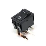
SWITCHES
POWER ROCKER SWITCH
FEATURES
Small size
AJ7 switch 10A type
Standard actuator
1. Power rocker switches for safety
requirements.
• All versions comply with ClassII
EN61058-1 insulation grade.
Insulation distance: 8mm Min.
Contact gap: 3mm Min.
• International Standard-approved
status
Already approved
Standard
actuator
UL/C-UL, ENEC/VDE
AJ7
switch type
10A
Wide
type
actuator
UL/C-UL, ENEC/VDE
type
AJ7 switch 6A type UL/C-UL, ENEC/VDE
AJ7 switch 10A type
Wide actuator
2. High inrush current resistance is
ideal for office automation equipment.
AJ7 switch 6A type
Inrush
10A type
100A
6A type
60A
Contact
Expected
rating
life
10A 250V AC
Min.104
6A 250V AC
3. Operation that only requires a light
touch
The best operation characteristics were
sought by analyzing touch data gathered
by monitoring 1,500 people.
• Power Rocker Switch touch curve
PRECAUTIONS WHEN
USING CADMIUM-FREE
CONTACT TYPE
Models with cadmium-free contacts have
been introduced in order to reduce
environmentally harmful substances. (“F”
is affixed to the end of the part number.)
We ask customers who are currently
using products with cadmium-containing
contacts (no “F” at the end of the part
number) to please make the switch to
models with cadmium-free contacts.
When switching, operating life may differ
depending on the load. Please be sure to
verify this by conducting an evaluation
using actual equipment.
Force
Compliance with RoHS Directive
Type
4. A broad product line
The AJ7 switches are available with five
different types of terminals: quickconnect terminals, soldering terminals,
PC board terminals, right angle terminals
and left angle terminals.
5. Eight standard actuator colors
White, black, red, dark gray, light gray,
blue, green, yellow
6. Cadmium-free contact compatibility.
7. TV-5 rating type added to lineup
Stroke
CONSTRUCTION
Case
Snap-in Clip
;;;;;;;;;;;;;;;
;;;
;;;;;
;;;;
;;;;;;;;;;
;;;;;
;;;
Actuator
Contact gap (more than 3mm)
The EN60950 (intended for office automation equipment)
conforms with a 3mm gap.
When directly opening or closing the primary power supply
side, a contact gap of at least 3mm is required in order to
ensure safety.
All Rights Reserved © COPYRIGHT Panasonic Electric Works Co., Ltd.
�AJ7 (J7)
ORDERING INFORMATION
AJ 7
F
7: AJ7 switch
Rating & size of actuator
Nil: 10A standard size
W: 10A wide size
6: 6A standard size
Number of poles and Operation
1: 1-pole, single throw (ON-OFF)
2: 2-pole, single throw (ON-OFF)
Terminal shape
0: .187 Quick-connect terminal
1: Soldering terminal
2: PC board terminal
3: PC board right angle terminal (for standard actuator only)
4: PC board left angle terminal (for standard actuator only)
Actuator indication
0: No indication
1:
indication (Indication on top)
2:
indication (Indication on top)
3:
4:
5:
indication (Side indication)
indication (Indication on top)
indication (Side indication)
Actuator color Remark 1)
W: White B: Black R: Red Z: Dark gray H: Light gray L: Blue G: Green Y: Yellow
Flange color
Nil: Black (standard color)
(Custom ordered color: W: White, R: Red, Z: Dark gray, H: Light gray, L: Blue, G: Green, Y: Yellow) Remark 1, 5)
Insulation guard
Nil: Short guard type
T: Long guard type (.187 Quick-connect terminal and soldering terminal only)
F: Cadmium-free product
Remarks: 1. The 10A type has indication on the actuator.
2. The correspondence between actuator colors and flange colors marked with an asterisk differs according to the type;
refer to the remark for the PRODUCT TYPES.
3. “I O” is engraved on all flanges.
4. The color of indication on the actuator:
• White actuator: black
• Others: white
5. The flange color of 6A type is black only.
6. They come with a stamp indicating international standards without your request.
TV rating type
AJ 7
2
B
TV
F
7: AJ7 switch
Number of poles and Operation
2: 2-pole, single throw (ON-OFF)
Terminal shape
0: .187 Quick-connect terminal
1: Soldering terminal
Actuator indication
0: No indication
2:
indication (Indication on top)
Actuator color
B: Black
Rating
TV: TV rating
F: Cadmium-free product
All Rights Reserved © COPYRIGHT Panasonic Electric Works Co., Ltd.
�AJ7 (J7)
ACTUATOR INDICATIONS ON PRODUCTS MADE TO ORDER
With indication on top
With side indication
(When the “ I ” indication is visible on the side of the actuator,
it indicates that the switch is in the “ON” state.)
With I O indications:
The I and O symbols are located on each side, respectively.
With I
indications:
The I symbols is located on the side.
PRODUCT TYPES
1. 10 A type
1) Standard actuator type
(1) Without indication on actuators
Terminal shape
.187 Quick-connect terminal
Soldering terminal
PC board terminal
PC board right angle terminal
PC board left angle terminal
Poles
Operating types
1-pole
2-pole
1-pole
2-pole
1-pole
2-pole
1-pole
2-pole
1-pole
2-pole
ON-OFF
Part No.
Without indication
AJ7100∗F
AJ7200∗F
AJ7110∗F
AJ7210∗F
AJ7120∗F
AJ7220∗F
AJ7130∗F
AJ7230∗F
AJ7140∗F
AJ7240∗F
Remarks: 1. A letter indicating the actuator color is entered in place of asterisk. (W: White, B: Black, R: Red, Z: Dark gray, H: Light gray, L: Blue, G: Green, and Y: Yellow).
Standard flange color is black. For other colors type, they are custom ordered. For requests of other flange color, please enter the following letter before the “F”
in the part number. (W: White, R: Red, Z: Dark gray, H: Light gray, L: Blue, G: Green and Y: Yellow)
2. Long guard type is available for .187 Quick-connect terminal and soldering terminal type. When ordering, please add a “T” before the “F” at the end of the part
number.
3. The color of indication on the actuator:
• For white actuator: black
• For others: white
4. They come with a stamp indicating international standards without your request.
5. Note that the position of the I mark on the flange is used as a reference for left angle and right angle terminals as shown in the diagram below. This also applies
to the 6A type.
I mark
Right angle terminal
I mark
Left angle terminal
All Rights Reserved © COPYRIGHT Panasonic Electric Works Co., Ltd.
�AJ7 (J7)
(2) With indication on actuators
Terminal shape
.187 Quick-connect terminal
Soldering terminal
PC board terminal
PC board right angle terminal
PC board left angle terminal
Poles
Operating types
1-pole
2-pole
1-pole
2-pole
1-pole
2-pole
1-pole
2-pole
1-pole
2-pole
ON-OFF
Part No.
With I O indication
AJ7101∗F
AJ7201∗F
AJ7111∗F
AJ7211∗F
AJ7121∗F
AJ7221∗F
AJ7131∗F
AJ7231∗F
AJ7141∗F
AJ7241∗F
With — O indication
AJ7102∗F
AJ7202∗F
AJ7112∗F
AJ7212∗F
AJ7122∗F
AJ7222∗F
AJ7132∗F
AJ7232∗F
AJ7142∗F
AJ7242∗F
Remarks: 1. A letter indicating the actuator color is entered in place of asterisk. (W: White, B: Black, R: Red, Z: Dark gray, H: Light gray, L: Blue, G: Green, and Y: Yellow).
Standard flange color is black. For other colors type, they are custom ordered. For requests of other flange color, please enter the following letter before the “F”
in the part number. (W: White, R: Red, Z: Dark gray, H: Light gray, L: Blue, G: Green and Y: Yellow)
2. Long guard type is available for .187 Quick-connect terminal and soldering terminal type. When ordering, please add a “T” before the “F” at the end of the part
number.
3. The color of indication on the actuator:
• For white actuator: black
• For others: white
4. They come with a stamp indicating international standards without your request.
5. Note that the position of the I mark on the flange is used as a reference for left angle and right angle terminals as shown in the diagram below. This also applies
to the 6A type.
I mark
I mark
Right angle terminal
Left angle terminal
2) Wide actuator type
(1) Without indication on actuators
Terminal shape
.187 Quick-connect terminal
Soldering terminal
PC board terminal
Poles
Operating types
1-pole
2-pole
1-pole
2-pole
1-pole
2-pole
ON-OFF
Poles
Operating types
1-pole
2-pole
1-pole
2-pole
1-pole
2-pole
ON-OFF
Part No.
Without indication
AJ7W100∗F
AJ7W200∗F
AJ7W110∗F
AJ7W210∗F
AJ7W120∗F
AJ7W220∗F
(2) With indication on actuators
Terminal shape
.187 Quick-connect terminal
Soldering terminal
PC board terminal
Part No.
With I O indication
AJ7W101∗F
AJ7W201∗F
AJ7W111∗F
AJ7W211∗F
AJ7W121∗F
AJ7W221∗F
With — O indication
AJ7W102∗F
AJ7W202∗F
AJ7W112∗F
AJ7W212∗F
AJ7W122∗F
AJ7W222∗F
Remarks: 1. A letter indicating the actuator color is entered in place of asterisk. (W: White, B: Black, R: Red, Z: Dark gray, H: Light gray, L: Blue, G: Green, and Y: Yellow).
Standard flange color is black. For other colors type, they are custom ordered. For requests of other flange color, please enter the following letter before the “F”
in the part number. (W: White, R: Red, Z: Dark gray, H: Light gray, L: Blue, G: Green and Y: Yellow)
2. The color of indication on the actuator:
• For white actuator: black
• For others: white
3. They come with a stamp indicating international standards without your request.
All Rights Reserved © COPYRIGHT Panasonic Electric Works Co., Ltd.
�AJ7 (J7)
2. 6 A type
1) Standard actuator type
(1) Without indication on actuators
Terminal shape
.187 Quick-connect terminal
Soldering terminal
PC board terminal
PC board right angle terminal
PC board left angle terminal
Poles
Operating types
1-pole
2-pole
1-pole
2-pole
1-pole
2-pole
1-pole
2-pole
1-pole
2-pole
ON-OFF
Poles
Operating types
1-pole
2-pole
1-pole
2-pole
1-pole
2-pole
1-pole
2-pole
1-pole
2-pole
ON-OFF
Part No.
Without indication
AJ76100∗F
AJ76200∗F
AJ76110∗F
AJ76210∗F
AJ76120∗F
AJ76220∗F
AJ76130∗F
AJ76230∗F
AJ76140∗F
AJ76240∗F
(2) With indication on actuators
Terminal shape
.187 Quick-connect terminal
Soldering terminal
PC board terminal
PC board right angle terminal
PC board left angle terminal
Part No.
With I O indication
AJ76101∗F
AJ76201∗F
AJ76111∗F
AJ76211∗F
AJ76121∗F
AJ76221∗F
AJ76131∗F
AJ76231∗F
AJ76141∗F
AJ76241∗F
With — O indication
AJ76102∗F
AJ76202∗F
AJ76112∗F
AJ76212∗F
AJ76122∗F
AJ76222∗F
AJ76132∗F
AJ76232∗F
AJ76142∗F
AJ76242∗F
(Standard color is black. For other color type, they are custom ordered.)
Remarks: 1. Replace the asterisk with a code that indicates the actuator color.
B: Black (standard), W: White (custom ordered), R: Red (custom ordered), Z: Dark gray (custom ordered), H: Light gray (custom ordered)
2. The color of I O indication on the actuator: White actuator: black Others: white
3. They come with a stamp indicating international standards without your request.
3. TV rating type
Terminal shape
Poles
Operating types
2-pole
ON-OFF
.187 Quick-connect terminal
Soldering terminal
Part No.
Without indication
AJ7200BTVF
—
AJ7210BTVF
—
With — O indication
—
AJ7202BTVF
—
AJ7212BTVF
SPECIFICATIONS
1. Contact rating
Type
Voltage
10A type
6A type
250V AC
Resistive load
(cos φ ] 1.0)
10A
6A
Motor load (EN61058-1)
(cos φ ] 0.6)
4A
3A
Inrush load
100A (8.3ms)
—
Remark: The motor load is in accordance with EN61058-1. Inrush current can be switched up to the value of 6 times the indicated rating.
2. TV rating
Voltage
120V AC
250V AC
Resistive load
(cos φ ] 1.0)
—
10A
Motor load (EN6105801)
(cos φ ] 0.6)
—
4A
Capacitor load (EN61058-1)
(Inrush load)
—
100A (8.3ms)
Lamp load (UL1054)
(TV-5)
5/78A
—
All Rights Reserved © COPYRIGHT Panasonic Electric Works Co., Ltd.
Expected electrical life
(at 7 cpm)
Min. 2.5 × 10⁴
Min. 104
�AJ7 (J7)
3. Characteristics
Expected life
(Min. operations)
Min. 5 × 10⁴ (at 20 cpm.)
Mechanical
Electrical*
Initial insulation resistance (Between terminals)
Initial breakdown voltage (Between terminals)
Initial contact resistance (By voltage drop at 1A, 2 to 4V DC)
at 6 × 10³ ope. or less
Temperature rise
from 6 × 10³ ope. to 104
Vibration resistance
Shock resistance
Actuator strength
Tensile terminal strength
Ambient temperature
Flame retardancy
Tracking resistance
1-pole
Operating force
(reference characteristics)
2-pole
Contact material
Min. 104 (at 7 cpm., at rated load)
Min. 100 MΩ (at 500V DC measured by insulation resistive meter)
2,000 Vrms detection current: 10 mA
Max. 100mΩ
Max. 30°C (UL1054)
Max. 55°C (EN61058-1)
10 to 55 Hz at double amplitude of 1.5mm
Min. 490m/s2{50 G}
40 N {4.08kgf} for 1 minute (operating direction)
100 N {10.2kgf} for 1 minute or more (Pull & push direction)
–25°C to +85°C (Not freezing below 0°C)
UL94V-0
Min. 175
2.2 ± 1.2N {0.22 ±0.12kgf}
4 ± 2.5N {0.41 ±0.25kgf}
AgSnO2 alloy
Remark: Test conditions are in accordance with EN61058-1, UL1054 and JIS C 6571.
* Except TV rating type
mm General tolerance: ±0.5
DIMENSIONS
The dimension diagram for the standard actuator types is common to both the 10A type and the 6A type.
1. .187 Quick-connect terminal/Long guard type
2-pole
21
Long guard type
.187 Quick-connect terminal
1-pole
21
15
12.8
10
32°±4°
ON
OFF
OFF
4.8
10
19
13
3
3
1.4 dia.
1.4 dia.
8.5
9
8.5
16.5
13
ON
2
5.3
2
5.3
32°±4°
0.8
8.75
12.5
4.375
4.8
10
19
Remark: As for soldering type, only terminal is different.
Diagram of recommended locations
for panel mounting holes
X
12.9 +0.1
−0
Panel thickness
0.75 to 1.25
1.25 to 2
2 to 3
All Rights Reserved © COPYRIGHT Panasonic Electric Works Co., Ltd.
X
19.2 +0
−0.1
19.4 +0
−0.1
19.8 +0
−0.1
�AJ7 (J7)
mm General tolerance: ±0.5
2. Soldering terminal
2-pole
21
Long guard type
Soldering terminal
1-pole
21
15
12.8
10
32°±4°
OFF
ON
2
OFF
1.6
10
19
13
0.8
8.75
12.5
4.375
8.5
9
2.6
2.6
8.5
16.5
13
ON
5.3
2
5.3
32°±4°
1.6
10
19
Diagram of recommended locations
for panel mounting holes
X
12.9 +0.1
−0
Panel thickness
0.75 to 1.25
1.25 to 2
2 to 3
X
19.2 +0
−0.1
19.4 +0
−0.1
19.8 +0
−0.1
3. PC board terminal
Diagram of recommended locations
for panel mounting holes
X
12.9 +0.1
−0
2-pole
21
1-pole
15
12.8
10
32°±4°
PC board pattern
2
5.3
2-pole
10±0.1
OFF
1-pole
4-1.8±0.1
16.5
4-1.8±0.1
10±0.1
13
ON
8.75±0.1
4
(7.5)
4.375±0.1
1.3
10
19
0.8
8.75
12.5
4.375
Panel thickness
0.75 to 1.25
1.25 to 2
2 to 3
X
19.2 +0
−0.1
19.4 +0
−0.1
19.8 +0
−0.1
4. PC board right angle terminal
Diagram of recommended locations
for panel mounting holes
X
12.9+0.10
17.5±0.3
2-pole
21
1-pole
15.0±0.3
15
12.8
10
32°±4°
PC board pattern
2
5.3
2-pole
10±0.1
OFF
1-pole
4-1.8±0.1
10±0.1
2-1.8±0.1
8±0.1
8
0.8
2
16.5
13
ON
Terminal side
19
Remark: A type left angle terminals is also available.
4
12.5
Panel thickness
0.75 to 1.25
1.25 to 2
2 to 3
All Rights Reserved © COPYRIGHT Panasonic Electric Works Co., Ltd.
X
19.2 +0
−0.1
19.4 +0
−0.1
19.8 +0
−0.1
�AJ7 (J7)
mm General tolerance: ±0.5
5. Wide actuator type
Diagram of recommended locations
for panel mounting holes
X
21.9+0.1
0
2-pole
21
1-pole
24
21.8
19
2
5.3
32°±4°
OFF
Panel thickness
1 to less than 1.8
1.8 to 2.3
3
8.5
16.5
13
ON
1.4 dia.
4.8
0.8
8.75
21
10
19
X
19.2 +0
−0.1
19.9 +0
−0.1
Remark: Dimensions for the terminals of soldering
terminal type and PC board terminal type
are the same as those of standard size type.
4.375
NOTES
1. Switch mounting
Mount the switch with the hole cutting
dimensions shown in the dimensions.
Contact us if you are considering using a
panel of other than the recommended
size and shape.
2. Regarding fastening lead wires to
terminals
1) When connecting the tab terminals,
use a .187 Quick-connect and insert the
terminals straight in.
If they are skewed, the terminals will
require excessive insertion force.
In addition, there is some variation in the
insertion force required for different
receptacles from different manufacturers,
so confirm how much force is needed
under actual conditions.
Do not solder wires onto tab terminals.
2) With manual soldering: Complete the
soldering connection work within 3
seconds with the tip of the soldering iron
(60W soldering iron) at a temperature of
420°C or lower, and take care not to
apply any force to the terminal area.
Avoid touching the switch with soldering
iron.
Soldering position
When wrapping or soldering a wire
around a terminal, do so in the shaded
area indicated in the diagram at left.
Contact terminal and ground terminal
Refer to the diagram above, “soldering
position,” for details on the position where
a wire should be soldered to a terminal.
When soldering PC board terminals,
keep soldering time to within 5 s at 270°C
soldering bath or within 3 s at 350°C
soldering bath.
3) The terminals should be connected in
such a way that they are not under
constant stress from the connecting
wires.
4) Terminal material is copper alloy which
may discolor due to finger’s oil or after a
long time. But that discoloration does not
effect actual performance.
3. Resistance to chemicals
To clean the switch unit, use a neutral
detergent diluted with water.
Do not use acidic or alkaline solvents as
they may damage the switch.
Furthermore, be careful not to get any of
the detergent solution inside of the switch
while cleaning it.
4. Environment
Avoid using and storing these switches in
a location where they will be exposed to
corrosive gases, silicon, or high dust
levels, all of which can have an adverse
effect on the contacts.
5. Take care not to drop the product as
it may impair perfomance.
REFERENCE
1. Outline of UL1054 test
Overload test AJ7: 15A 250V AC
(Power factor 0.75 to 0.8)
50 operation
Endurance test AJ7: 10A 250V AC
(Power factor 0.75 to 0.8)
6×10³ operation
After testing, temperature rise of
terminals should be less than 30°C and
no abnormality should be observed in
characteristics.
2. Outline of EN61058-1 test
After switching 5 × 10³ times on the below
load condition at both 85 +50 °C and
25±10°C, temperature rise of terminals
should be less than 55°C and no
abnormality should be observed in
characteristics.
50 to 100ms
24A
J7: 10A
AC: 250V
(Power factor 0.6)
2 sec.
4 sec.
All Rights Reserved © COPYRIGHT Panasonic Electric Works Co., Ltd.
�AJ7 (J7)
INTRODUCTION TO 4P CONNECTORS FOR THE AJ7 SWITCH
(produced by Nippon Tanshi co., Ltd)
Suitable switches: AJ7 switch, .187 Quick-connect terminal
(Note: Terminal guard long type switches are not suitable for this connector.)
Housing
Product number: 4120-4204
Receptacle
Product number: 171901-M2
Notes) This AJ7 switch connector is not
available from Matsushita Electric Works.
Contact us for further details on this connector.
All Rights Reserved © COPYRIGHT Panasonic Electric Works Co., Ltd.
�Mouser Electronics
Authorized Distributor
Click to View Pricing, Inventory, Delivery & Lifecycle Information:
Panasonic:
AJ7241BF AJ7202BF AJ7231BF
�


 工商网监
湘ICP备2023018690号
工商网监
湘ICP备2023018690号

