Automation Controls Catalog
26.5 GHz max. Coaxial
switches coming in SPDT
and Compact size
FEATURES
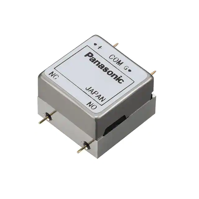
PIN type
1. Compact size (Approx. 85% less
volume compared to our previous
product.*)
PIN type size: L 15.9 × W 15.9 × H
11.2 mm L .626 × W .626 × H .441
inch
2. Excellent high frequency
characteristics (to 8, 18, 26.5GHz,
50Ω)
3. Terminal shape options available
(PIN and SMA)
4. Contact arrangement: SPDT
5. Failsafe type and latching type
(2-coil latching type) that reduces
operating power are now available.
SMA type
RV COAXIAL
SWITCHES (ARV)
TYPICAL APPLICATIONS
Compact wireless devices
Compact measuring instrument
All types of inspection equipment
Digital broadcasting
• Broadcasting relay station
• Broadcasting equipment
Mobile communication
• Cellular phone base station
If you consider using applications with
low level loads or with high frequency
switching, please consult us.
* Compared to previous product (RD coaxial switch)
and PIN type RV coaxial switch.
HIGH FREQUENCY CHARACTERISTICS (Impedance 50Ω, Initial)
1. PIN type
Frequency
V.S.W.R. (max.)
Insertion loss (dB. max.)
Isolation (dB. min.)
to 4 GHz
1.3
0.3
70
4 to 8 GHz
1.4
0.4
60
8 to 12.4 GHz*
1.5
0.5
50
12.4 to 18 GHz*
1.7
0.7
40
8 to 12.4 GHz*
1.6
0.5
60
12.4 to 18 GHz*
1.7
0.7
60
18 to 26.5 GHz**
1.8
0.8
50
Note: *8 to 18GHz characteristics can be applied 18GHz type only.
2. SMA type
Frequency
V.S.W.R. (max.)
Insertion loss (dB. max.)
Isolation (dB. min.)
to 8 GHz
1.35
0.3
70
Note: *8 to 18GHz characteristics can be applied 18GHz type and 26.5GHz type only.
**18 to 26.5GHz characteristics can be applied 26.5GHz type only.
2019.03
industrial.panasonic.com/ac/e/
1
© Panasonic Corporation 2019
ASCTB107E 201903
�RV (ARV)
ORDERING INFORMATION
ARV
Frequency
1: to 8GHz
2: to 18GHz
3: to 26.5GHz (SMA type only)
Operating function
0: Failsafe type/Standard contact
2: Latching type/Standard contact
3: Failsafe type/Reverse contact
Terminal shape
N: PIN type
A: SMA type
Nominal operating voltage
4H: 4.5 V DC
12: 12 V DC
24: 24 V DC
Operation terminal
Nil: Solder terminal
HF data attached
Nil: No HF test data attached
Q: HF test data attached (Displayed only on inner and outer packaging)
*Please inquire regarding use with nominal operating voltage of 28 V DC.
TYPES
SPDT
Operating
function
Contact
terminal
shape
PIN type
Failsafe type/
Standard contact
SMA type
PIN type
Latching type/
Standard contact
SMA type
PIN type
Failsafe type/
Reverse contact
SMA type
Nominal
operating
voltage
4.5 V DC
12 V DC
24 V DC
4.5 V DC
12 V DC
24 V DC
4.5 V DC
12 V DC
24 V DC
4.5 V DC
12 V DC
24 V DC
4.5 V DC
12 V DC
24 V DC
4.5 V DC
12 V DC
24 V DC
to 8 GHz type
No HF datasheet
HF datasheet
attached
attached
ARV10N4H
ARV10N4HQ
ARV10N12
ARV10N12Q
ARV10N24
ARV10N24Q
ARV10A4H
ARV10A4HQ
ARV10A12
ARV10A12Q
ARV10A24
ARV10A24Q
ARV12N4H
ARV12N4HQ
ARV12N12
ARV12N12Q
ARV12N24
ARV12N24Q
ARV12A4H
ARV12A4HQ
ARV12A12
ARV12A12Q
ARV12A24
ARV12A24Q
ARV13N4H
ARV13N4HQ
ARV13N12
ARV13N12Q
ARV13N24
ARV13N24Q
ARV13A4H
ARV13A4HQ
ARV13A12
ARV13A12Q
ARV13A24
ARV13A24Q
to 18 GHz type
No HF datasheet
HF datasheet
attached
attached
ARV20N4H
ARV20N4HQ
ARV20N12
ARV20N12Q
ARV20N24
ARV20N24Q
ARV20A4H
ARV20A4HQ
ARV20A12
ARV20A12Q
ARV20A24
ARV20A24Q
ARV22N4H
ARV22N4HQ
ARV22N12
ARV22N12Q
ARV22N24
ARV22N24Q
ARV22A4H
ARV22A4HQ
ARV22A12
ARV22A12Q
ARV22A24
ARV22A24Q
ARV23N4H
ARV23N4HQ
ARV23N12
ARV23N12Q
ARV23N24
ARV23N24Q
ARV23A4H
ARV23A4HQ
ARV23A12
ARV23A12Q
ARV23A24
ARV23A24Q
to 26.5 GHz type
No HF datasheet
HF datasheet
attached
attached
–
–
–
–
–
–
ARV30A4H
ARV30A4HQ
ARV30A12
ARV30A12Q
ARV30A24
ARV30A24Q
–
–
–
–
–
–
ARV32A4H
ARV32A4HQ
ARV32A12
ARV32A12Q
ARV32A24
ARV32A24Q
–
–
–
–
–
–
ARV33A4H
ARV33A4HQ
ARV33A12
ARV33A12Q
ARV33A24
ARV33A24Q
Standard packing: Carton: 5 pcs. Case: 50 pcs.
Panasonic Corporation Electromechanical Control Business Division
industrial.panasonic.com/ac/e/
2
© Panasonic Corporation 2019
ASCTB107E 201903
�RV (ARV)
RATING
1.Coil data
• Operating characteristics such as ‘Operate voltage’ and ‘Release voltage’ are influenced by mounting conditions, ambient
temperature, etc.
Therefore, please use the relay within ± 5% of rated coil voltage.
• ‘Initial’ means the condition of products at the time of delivery.
1) Failsafe type (Standard contact and Reverse contact)
Nominal operating
voltage
Pick-up voltage
(at 20°C 68°F)
Drop-out voltage
(at 20°C 68°F)
4.5 V DC
12 V DC
24 V DC
75%V or less
of nominal voltage*1
(Initial)
10%V or more
of nominal voltage*1
(Initial)
Nominal operating
current
[±10%] (at 20°C 68°F)
155.7 mA
58.3 mA
29.2 mA
Coil resistance [±10%]
(at 20°C 68°F)
Nominal operating
power
Max. applied voltage
(at 85°C 185°F)
700 mW
110%V
of nominal voltage
Coil resistance [±10%]
(at 20°C 68°F)
Nominal operating
power
Max. applied voltage
(at 85°C 185°F)
28.9 Ω
205.7 Ω
822.9 Ω
700 mW
110%V
of nominal voltage
28.9 Ω
205.7 Ω
822.9 Ω
2) Latching type (Standard contact)
Nominal operating
voltage
Set voltage
(at 20°C 68°F)
Reset voltage
(at 20°C 68°F)
4.5 V DC
12 V DC
24 V DC
75%V or less
of nominal voltage*1
(Initial)
75%V or less
of nominal voltage*1
(Initial)
Nominal operating
current
[±10%] (at 20°C 68°F)
155.7 mA
58.3 mA
29.2 mA
Notes: *1. Pulse drive (JIS C5442)
*2. Please inquire regarding use with nominal operating voltage of 28 V DC.
2. Specifications
Characteristics
Contact
Rating
High frequency
characteristics
(Impedance 50Ω)
Electrical
characteristics
Time characteristics
(at 20°C 68°F)
Mechanical
characteristics
Item
Arrangement
Contact material
Contact resistance (Initial)
Contact input power (CW)
Nominal operating power
Frequency
V.S.W.R. (max.)
Insertion loss (dB, max.)
Isolation (dB, min.)
Insulation resistance (Initial)
Between open
contacts
Between contact
Breakdown and earth terminal
voltage
Between contact
(Initial)
and coil
Between coil and
earth terminal
Operate time (Set time)
Release time (Reset time)
Shock
resistance
Vibration
resistance
Functional
Destructive
Functional
Destructive
Expected life
Mechanical
Electrical (Hot switch)
Conditions
Conditions for operation, transport
and storage*6
Unit weight
Specifications
SPDT
Gold plating
Max. 100mΩ (By voltage drop 10V AC 10mA)
Max. 50W (at 3GHz) (V.S.W.R. 1.3 or less, no contact switching, ambient temperature 20°C 68°F)*1
700mW
SMA type
PIN type*2
12.4 to 18
12.4 to 18
18 to 26.5
8 to 12.4
8 to 12.4
to 4 GHz
4 to 8 GHz
to 8 GHz
GHz*3
GHz*4
GHz*5
GHz*3
GHz*4
1.3
1.4
1.5
1.7
1.35
1.6
1.7
1.8
0.3
0.4
0.5
0.7
0.3
0.5
0.7
0.8
70
60
50
40
70
60
60
50
Min. 1,000 MΩ (at 500 V DC) Measurement at same location as “breakdown voltage (Initial)” section.
500 Vrms for 1 min. (Detection current: 10mA)
500 Vrms for 1 min. (Detection current: 10mA)
500 Vrms for 1 min. (Detection current: 10mA)
500 Vrms for 1 min. (Detection current: 10mA)
Max. 15ms (approx. 5ms) (Nominal operating voltage applied to the coil, excluding contact bounce time.)
Max. 15ms (approx. 5ms) (Nominal operating voltage applied to the coil, excluding contact bounce time.)
(without diode, only for Release time)
Min. 500 m/s2 (Half-wave pulse of sine wave: 11ms, detection time: 10µs.)
Min. 1,000 m/s2 (Half-wave pulse of sine wave: 6ms.)
10 to 55 Hz at double amplitude of 3mm (Detection time: 10µs.)
10 to 55 Hz at double amplitude of 5mm/15 to 2,000 Hz [W0 = 2.94 (m/s2)2/Hz]
Min. 106 (at 180 cpm)
Min. 3 × 10⁵ (1W High frequency load, at 3GHz, impedance 50Ω, V.S.W.R.; max. 1.3) (at 20 cpm)
Ambient temperature: –55°C to +85°C –67°F to +185°F
Humidity: 5 to 85% R.H. (Not freezing and condensing at low temperature)
Air pressure: 86 to 106 kPa
PIN type: Approx. 12g .42oz
SMA type: Approx. 20g .71oz
Notes: *1. Factors such as heating of the connected terminal influence the high frequency characteristics; therefore, please verify under actual conditions of use.
*2. Measuring method: After installing on dedicated inspection equipment
*3. 8 to 18GHz characteristics can be applied 18GHz type only.
*4. 8 to 18GHz characteristics can be applied 18GHz and 26.5GHz types only.
*5. 18 to 26.5GHz characteristics can be applied 26.5GHz type only.
*6. The upper operation ambient temperature limit is the maximum temperature that can satisfy the coil temperature rise value. Refer to “NOTES”.
Panasonic Corporation Electromechanical Control Business Division
industrial.panasonic.com/ac/e/
3
© Panasonic Corporation 2019
ASCTB107E 201903
�RV (ARV)
REFERENCE DATA
1-(1). High frequency characteristics (PIN type)
Sample: ARV22N12
Measuring method: Measured with Agilent Technologies network analyzer (E8363B) after installing on dedicated inspection equipment.
• Insertion loss
• Isolation
2.0
0.0
0
1.9
0.1
10
1.8
0.2
Standard value
1.6
1.5
COM-1
1.4
1.3
1.2
Reference value
1.1
1.0
COM-2
0.3
0.4
0.5 Standard value
0.6
20
COM-1
40
Standard value
50
COM-1
60
70
0.8
80
1.0
18GHz
8GHz 12.4GHz
Frequency
30
0.7
0.9
COM-2
4GHz
Reference value
Isolation, dB
1.7
Insertion loss, dB
V.S.W.R.
• V.S.W.R.
Reference value
90
4GHz
8GHz 12.4GHz
Frequency
100
18GHz
COM-2
4GHz
8GHz 12.4GHz
Frequency
18GHz
1-(2). High frequency characteristics (SMA type)
Sample: ARV32A12
Measuring method: Measured with Agilent Technologies network analyzer (E8363B).
• Insertion loss
0.0
1.9
0.1
1.8
0.2
1.7
Standard value
1.6
1.5
1.4
Reference value
COM-2
1.3
• solation
Reference value
0
COM-1
20
0.3
0.4
COM-2
0.5
0.6
10
Isolation, dB
2.0
Insertion loss, dB
V.S.W.R.
• V.S.W.R.
30
40
50
Standard value
0.7
70
1.2
0.8
80
1.1
0.9
90
1.0
100
1.0
COM-1
8GHz 12.4GHz 18GHz
Frequency
26.5GHz
8GHz 12.4GHz 18GHz
Frequency
Panasonic Corporation Electromechanical Control Business Division
industrial.panasonic.com/ac/e/
Standard value
COM-2
60
4
26.5GHz
Reference value
COM-1
8GHz 12.4GHz 18GHz
Frequency
© Panasonic Corporation 2019
26.5GHz
ASCTB107E 201903
�RV (ARV)
DIMENSIONS (mm inch)
1. PIN type
The CAD data of the products with a CAD Data mark can be downloaded from https://industrial.panasonic.com/ac/e/
15.90
.626
CAD Data
Schematic (Top view)
Failsafe type
3-0.45 dia.
3-.018 dia.
3-0.40×0.25
3-.016×.010
(Deenergized condition)
COM
15.70
.618
2.00
.079
10.16
.400
2.54
.100
6.20
.244
1.50
.059
Latching type only
2.30
.091
GND
4.83
.190
NC
NO
Latching type
The part number depend on
the type and voltage.
(Reset condition)
3.80
.150
15.50
.610
Lot number
15.90
.626
Coil 1
10.16
.400
Coil 2
COM
10.16
.400
5.10
.201
11.20
.441
2.30
.091
Metric course thread/internal thread
4-M 1.6 (2.5 mm depth)
1
2
1
2
Failsafe type
(Deenergized condition)
Tolerance: ±0.3 ±.012
COM
NO
2. SMA type
NC
Schematic (Top view)
Failsafe type
17.80
.701
CAD Data
GND
(Deenergized condition)
3-0.40×0.25
3-.016×.010
COM
2.95
.116
15.70
.618
10.16
.400
2.54
.100
Latching type only
8.30
.327
3.60
.142
5.08
.200
NC
GND
NO
Latching type
7.70
.303
(Reset condition)
Coil 1
2.75
.108
The part number depend on
the type and voltage.
Coil 2
15.50
.610
Lot number
18.00
.709
10.16
.400
1
7.70
.303
10.16
.400
7.20
.283
13.30
.524
COM
Metric course thread/internal thread
4-M 1.6 (2.5 mm depth)
2
1
2
Failsafe type
(Deenergized condition)
3-SMA connector
COM
GND
Tolerance: ±0.3 ±.012
NO
*For SMP connector type, please consult us.
Panasonic Corporation Electromechanical Control Business Division
industrial.panasonic.com/ac/e/
5
© Panasonic Corporation 2019
NC
ASCTB107E 201903
�RV (ARV)
NOTES
1. For general cautions for use, please
refer to the “General Application
Guidelines”.
2. Coil operating power
Pure DC current should be applied to the
coil. The wave form should be
rectangular. If it includes ripple, the ripple
factor should be less than 5%.
However, check it with the actual circuit
since the characteristics may be slightly
different. The nominal operating voltage
should be applied to the coil for more
than 50 ms to set/reset the latching type.
Please use the latching type for circuits
that are continually powered for long
periods of time.
3. Coil connection
Since this product is polarized, please be
aware of the plus/minus polarity of the
coil.
4. Connection and washing conditions
for coil and PIN type contact terminals
1) The connection of coil and PIN type
contact terminals shall be done by
soldering.
Soldering conditions
Max. 260°C 500°F (solder temp) within
10sec (soldering time)
Max. 350°C 662°F (solder temp) within
3sec (soldering time)
2) This product is not sealed type,
therefore washing is not allowed.
5. Conditions for operation, transport
and storage conditions
1) Temperature:
–55 to +85°C –67 to +185°F
2) Humidity: 5 to 85% RH
(Avoid freezing and condensation.)
The humidity range varies with the
temperature. Use within the range
indicated in the graph below.
3) Atmospheric pressure: 86 to 106 kPa
Temperature and humidity range for
usage, transport, and storage:
Humidity, %RH
85
Tolerance range
(Avoid freezing when
used at temperatures
lower than 0°C 32°F)
5
–55
–67
(Avoid
condensation when
used at temperatures
higher than 0°C 32°F)
0
+32
Temperature, °C °F
+85
+185
4) Condensation
Condensation forms when there is a
sudden change in temperature under
high temperature and high humidity
conditions. Condensation will cause
deterioration of coaxial switch insulation.
5) Freezing
Condensation or other moisture may
freeze on coaxial switch when the
temperature is lower than 0°C 32°F. This
causes problems such as sticking of
movable parts or operational time lags.
6) Low temperature, low humidity
environments.
The plastic may become brittle if coaxial
switch is exposed to a low temperature,
low humidity environment for long periods
of time.
6. Other handling precautions.
1) Coaxial switch’s on/off service life is
based on standard test conditions
(temperature: 15 to 35°C 59 to 95°F,
humidity: 25 to 75%) specified in JIS
C5442-1996. Life will depend on many
factors of your system: coil drive circuit,
type of load, switching intervals,
switching phase, ambient conditions, to
name a few.
2) Use coaxial switch within
specifications such as coil rating, contact
rating and on/off service life. If used
beyond limits, coaxial switch may
overheat, generate smoke or catch fire.
3) Be careful not to drop coaxial switch. If
accidentally dropped, carefully check its
appearance and characteristics before
use.
4) Be careful to wire coaxial switch
correctly. Otherwise, malfunction,
overheat, fire or other trouble may occur.
5) The latching type product is shipped in
the reset position. But jolts during
transport or impacts during installation
can move it to the set position. It is,
therefore, advisable to build a circuit in
which coaxial switch can be initialized
(set and reset) just after turning on the
power.
6) If coaxial switch stays on in a circuit for
many months or years at a time without
being activated, circuit design should be
reviewed so that the coaxial switch can
remain deenergized. A coil that receives
current all the time heats, which
degrades insulation earlier than
expected. A latching type is
recommended for such circuits.
7) For SMA connectors (SMA type only),
we recommend a torque of 0.90±0.1 N·m
for installation, which falls within the
prescribed torque of MIL-C-39012.
Please be aware that conditions might be
different depending on the connector
materials and how it interacts with
surrounding materials.
8) Please do not use silicon based
substances such as silicon rubber, silicon
oil, silicon coatings and silicon fillings, in
the vicinity of the coaxial switch. Doing so
may cause volatile silicon gas to form
which may lead to contact failure due to
the adherence of silicon on the contacts
when they open and close in this
atmosphere.
9) In order to ensure stable signal
communication on contact, it is
recommended that the monitoring of
contact signal should be started from
Min. 100 ms after coil rated voltage is
applied.
Please refer to "the latest product specifications"
when designing your product.
• Requests to customers :
https://industrial.panasonic.com/ac/e/salespolicies/
Panasonic Corporation Electromechanical Control Business Division
industrial.panasonic.com/ac/e/
6
© Panasonic Corporation 2019
ASCTB107E 201903
�GUIDELINES FOR MICROWAVE DEVICES USAGE
For cautions for use, please read “GUIDELINES FOR RELAY USAGE”.
https://industrial.panasonic.com/ac/e/control/relay/cautions_use/index.jsp
Precautions for Coil Input
DC Coil operating power
Steady state DC current should be applied to the coil. The wave form
should be rectangular. If it includes ripple, the ripple factor should be
less than 5%.
However, please check with the actual circuit since the electrical
characteristics may vary. The rated coil voltage should be applied to
the coil and the set/reset pulse time of latching type relay differs for
each relays, please refer to the relay's individual specifications.
Coil connection
When connecting coils of polarized relays, please check coil polarity
(+,-) at the internal connection diagram (Schematic). If any wrong
connection is made, it may cause unexpected malfunction, like
abnormal heat, fire and so on, and circuit do not work. Avoid
impressing voltages to the set coil and reset coil at the same time.
Maximum allowable voltage and temperature rise
Proper usage requires that the rated coil voltage be impressed on the
coil. Note, however, that if a voltage greater than or equal to the
maximum continuous voltage is impressed on the coil, the coil may
burn or its layers short due to the temperature rise. Furthermore, do
not exceed the usable ambient temperature range listed in the catalog.
Maximum allowable voltage for coil
In addition to being a requirement for relay operation stability, the
maximum continuous impressed coil voltage is an important constraint
for the prevention of such problems as thermal deterioration or
deformity of the insulation material, or the occurrence of fire hazards.
Temperature rise due to pulse voltage
When a pulse voltage with ON time of less than 2 minutes is used, the
coil temperature rise bares no relationship to the ON time. This varies
with the ratio of ON time to OFF time, and compared with continuous
current passage, it is rather small. The various relays are essentially
the same in this respect.
Current passage time
(%)
For continuousu passage
Tempereture rise value is 100%
ON : OFF = 3 : 1
About 80%
ON : OFF = 1 : 1
About 50%
ON : OFF = 1 : 3
About 35%
ON : OFF = 1 : 1
Voltage
Long term current carrying
A circuit that will be carrying a current continuously for long periods
without relay or microwave device switching operation. (circuits for
emergency lamps, alarm devices and error inspection that, for
example, revert only during malfunction and output warnings with form
B contacts) Continuous, long-term current to the coil will facilitate
deterioration of coil insulation and characteristics due to heating of the
coil itself.
For circuits such as these, please use a magnetic-hold type latching
relay. If you need to use a single stable relay, use a sealed type relay
that is not easily affected by ambient conditions and make a failsafe
circuit design that considers the possibility of contact failure or
disconnection.
Time
Operate voltage change due to coil temperature rise
(Hot start)
In DC relays, after continuous passage of current in the coil, if the
current is turned OFF, then immediately turned ON again, due to the
temperature rise in the coil, the pick-up voltage will become somewhat
higher. Also, it will be the same as using it in a higher temperature
atmosphere. The resistance/temperature relationship for copper wire
is about 0.4% for 1°C, and with this ratio the coil resistance increases.
That is, in order to operate of the relay, it is necessary that the voltage
be higher than the pick-up voltage and the pick-up voltage rises in
accordance with the increase in the resistance value. However, for
some polarized relays, this rate of change is considerably smaller.
Ambient Environment
Dew condensation
Condensation occurs when the ambient temperature drops suddenly
from a high temperature and humidity, or the relay and microwave
device is suddenly transferred from a low ambient temperature to a
high temperature and humidity. Condensation causes the failures like
insulation deterioration, wire disconnection and rust etc.
Panasonic Corporation does not guarantee the failures caused by
condensation.
The heat conduction by the equipment may accelerate the cooling of
device itself, and the condensation may occur.
Please conduct product evaluations in the worst condition of the actual
usage. (Special attention should be paid when high temperature
heating parts are close to the device. Also please consider the
condensation may occur inside of the device.)
Icing
Condensation or other moisture may freeze on relays when the
temperature become lower than 0°C.This icing causes the sticking of
movable portion, the operation delay and the contact conduction failure
etc. Panasonic Corporation does not guarantee the failures caused by
the icing.
The heat conduction by the equipment may accelerate the cooling of
relay itself and the icing may occur. Please conduct product
evaluations in the worst condition of the actual usage.
Panasonic Corporation Electromechanical Control Business Division
industrial.panasonic.com/ac/e/
Low temperature and low humidity
The plastic becomes brittle if the switch is exposed to a low
temperature, low humidity environment for long periods of time.
High temperature and high humidity
Storage for extended periods of time (including transportation periods)
at high temperature or high humidity levels or in atmospheres with
organic gases or sulfide gases may cause a sulfide film or oxide film to
form on the surfaces of the contacts and/or it may interfere with the
functions. Check out the atmosphere in which the units are to be
stored and transported.
Package
In terms of the packing format used, make every effort to keep the
effects of moisture, organic gases and sulfide gases to the absolute
minimum.
c Panasonic Corporation 2019
ASCTB403E 201905
�GUIDELINES FOR MICROWAVE DEVICES USAGE
Storage requirements
Since the SMD type is sensitive to humidity it is packaged with tightly
sealed anti-humidity packaging. However, when storing, please be
careful of the following.
1) �Please use promptly once the anti-humidity pack is opened.(within
72 hours, Max. 30°C/70% R.H.). If left with the pack open, the relay
will absorb moisture which will cause thermal stress when reflow
mounting and thus cause the case to expand. As a result, the seal
may break.
*�For RE relays, after this bag is opened, the product must be used
within 24 hours.
2) �If relays will not be used within 72 hours, please store relays in a
humidity controlled desiccator or in an anti-humidity bag to which
silica gel has been added.
*�If the relay is to be soldered after it has been exposed to excessive
humidity atmosphere, cracks and leaks can occur. Be sure to mount
the relay under the required mounting conditions
*�For RE relays, after this bag is opened, the product must be used
within 24 hours.
3) �The following cautionary label is affixed to the anti-humidity pack.
Silicon
When a source of silicone substances (silicone rubber, silicone oil,
silicone coating materials and silicone filling materials etc.) is used
around the relay, the silicone gas (low molecular siloxane etc.) may be
produced.
This silicone gas may penetrate into the inside of the relay. When the
relay is kept and used in this condition, silicone compound may adhere
to the relay contacts which may cause the contact failure. Do not use
any sources of silicone gas around the relay (Including plastic seal
types).
NOx Generation
When relay is used in an atmosphere high in humidity to switch a load
which easily produces an arc, the NOx created by the arc and the
water absorbed from outside the relay combine to produce nitric acid.
This corrodes the internal metal parts and adversely affects operation.
Avoid use at an ambient humidity of 85%RH or higher (at 20°C). If use
at high humidity is unavoidable, please contact our sales
representative.
*RE Relays only
Others
Cleaning
1) �Although the environmentally sealed type relay (plastic sealed type,
etc.) can be cleaned, avoid immersing the relay into cold liquid (such
as cleaning solvent) immediately after soldering. Doing so may
deteriorate the sealing performance.
2) �Surface mount terminal type relay is sealed type and it can be
cleaned by immersion. Use pure water or alcohol-based cleaning
solvent.
3) �Cleaning with the boiling method is recommended (The temperature
of cleaning liquid should be 40°C or lower).
Avoid ultrasonic cleaning on relays. Use of ultrasonic cleaning may
cause breaks in the coil or slight sticking of the contacts due to the
ultrasonic energy.
Other handling precautions
・Expected switching life is defined under the standard test conditions
(temperature 15 to 35°C, humidity: 25 to 75%) specified in JIS C
5442.
Expected switching life is depend on usage conditions; coil driving
circuit, load type, activation frequency, activation phase, ambient
conditions and other factors. Please check relays and microwave
devices on the actual circuit.
Also, pay special attention loads such as those listed below.
・When used for AC load-operating and the operating phase is
synchronous, rocking and fusing can easily occur due to contact
shifting.
・Frequent switching under load condition
�When high frequently switched under load condition that can cause
arc at the contacts, nitrogen and oxygen in the air is fused by the
arc energy and HNO3 is formed. This can corrode metal materials.
Countermeasures for these are.
1. Incorporate an arc-extinguishing circuit.
2. Lower the operating frequency
3. Lower the ambient humidity
・When used for ‘‘Dry switching’’ without load current, please contact
our sales representative.
・Please avoid relays to be used outside of the specification ranges
such as the coil rating, contact rating and switching life that may
cause abnormal heating, smoke, and fire.
・In case relays and microwave devices are dropped, please do not
use.
Please refer to "the latest product specifications"
when designing your product.
•Requests to customers:
https://industrial.panasonic.com/ac/e/salespolicies/
Panasonic Corporation Electromechanical Control Business Division
industrial.panasonic.com/ac/e/
c Panasonic Corporation 2019
ASCTB403E 201905
�Please contact ..........
Electromechanical Control Business Division
1006, Oaza Kadoma, Kadoma-shi, Osaka 571-8506, Japan
industral.panasonic.com/ac/e/
©Panasonic Corporation 2019
ASCTB107E 201907
Specifications are subject to change without notice.
�


 工商网监
湘ICP备2023018690号
工商网监
湘ICP备2023018690号
