SUBMINIATURE SIZE
LIMIT SWITCHES
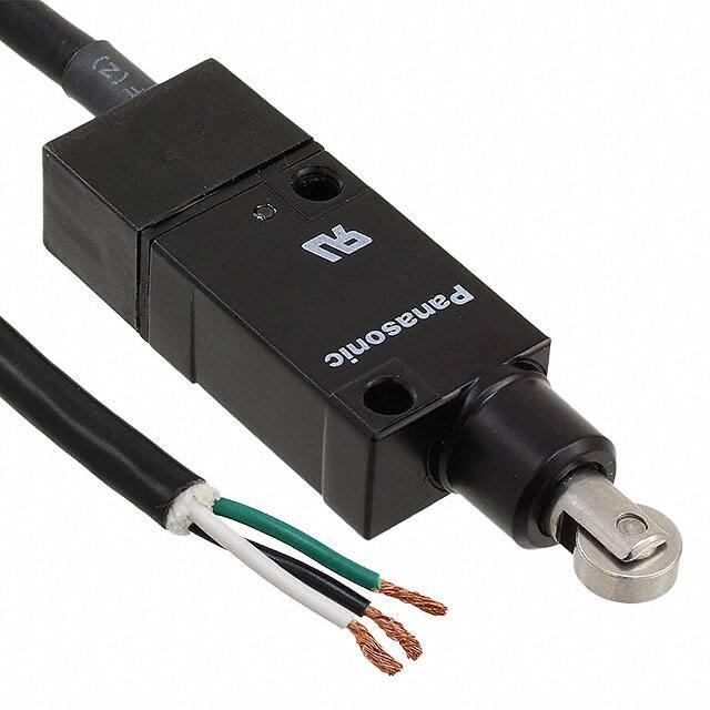
QL (AZ4) Micro
Limit Switches
High precision micro limit switches with excellent environment proofing
Quickly upgraded to limit switches with lamps by mounting an LED lamp socket
An exposed terminal type model combined with a socket with cord for the
built-in LED lamp (sold separately) easily
become a limit switch with lamp.
Convenient for maintenance such as
operations checks.
QL exposed
terminal type
QL limit
with lamp
Socket with
LED lamp
LED lamp
L socket type (roller arm)
Compliance with RoHS Directive
FEATURES
1. Subminiature design
The size of the actual unit is approximately 1/10 in the case of the plunger
model and approximately 1/6.5 in the
case of the arm model, that of the vertical type limit switch.
Large-scale miniaturization has been
achieved. Ideal for miniaturized machinery designs or highly accurate miniaturized machines.
Approx. 1/10
r
Plunger model
Vertical type
QL
2. A lamp can be easily added for
operations checks
3. With appropriate O.T. range display
The arm model has a convenient appropriate O.T. range display for attachment
adjustment work. This should be set so
that the operations display board’s indicated protrusion winds inside the protrusion on the axle receptor, permitting use
under optimum conditions.
O.T. exceeded
Appropriate range
Insufficient O.T. range
Appropriate range
Operating display board
O.T. exceeded
4. Terminal uses both solder and tab
(#110)
5. O.P. accuracy of ±0.2 (O.P. repeated
accuracy initially ±0.03) achieved
Attachment accuracy improved greatly
The plunger model has achieved a high
O.P. repeated accuracy of within
0.03mm through the development of a
unique switch mechanism and a standard attachment surface on the upper
surface of the unit (a surface with no
slants.)
Also, through a unique mechanism that
permits adjustment of the O.P. in each
individual product at the time of assem-
bly, an O.P. accuracy of ±0.2mm
.008inch can be safeguarded between
lots, so that almost no operating position
adjustment is required during either
attachment or replacement.
6. A subminiature limit switch with a
great stroke margin (O.T./T.T.)
The T.T. has been enlarged by using a
switching mechanism by coil spring for
QL.
7. Long life
The unit has a long mechanical life of
minimum 107 times and a long electrical
life of min. 3 � 105 times (5A, 250V AC
resistance load) by means of a silver
alloy contact with excellent solvent-proof
characteristics and a guaranteed wiping
operation that possesses two hinges and
switching method by coil spring.
8. A mechanism with excellent environment proofing
• A protective construction equivalent to
IEC IP64
The actuator has an axle seal with special packing, and the main case and terminals have both a waterproof ring and
an epoxy-sealed mechanism. Also, the
entire mechanism is water-proof due to
the optional socket.
Socket with cord type... IP64 equivalent
• A sturdy, shockproof construction
The body uses die-cast zinc, and the
actuator uses stainless steel. Moreover,
shock absorbers have been added to
lessen the shock during plunger release.
TYPICAL APPLICATIONS
Any application where compactness,
density, and robustness, such as subminiaturized machines and plant machinery, is required.
PRODUCT TYPE
1. Switch body
Actuator
Push plunger
Roller plunger
Cross roller plunger
Roller arm
Adjustable rod
Adjustable roller arm
Exposed terminal type
AZ4001
AZ4002
AZ4003
AZ4004
AZ4007
AZ4008
L socket type*
AZ4601
AZ4602
AZ4603
AZ4604
AZ4607
AZ4608
Notes) 1. Cadmium free contact types are available on a custom-made basis. Please add an “F” to the end of the part number when ordering.
2. *L socket type or socket with cord type is combination of;
L socket type = Exposed terminal type + L socket, Socket with cord type = Exposed terminal type + Socket with cord type (cord length: 1m)
3. UL recognized, CSA certified type available. When ordering, add suffix 9 to part No..
(For the socket with cord type, only UL recognized type available with suffix 9 to the part No.)
All Rights Reserved © COPYRIGHT Panasonic Electric Works Co., Ltd.
Socket with cord type*
AZ4701
AZ4702
AZ4703
AZ4704
AZ4707
AZ4708
�QL (AZ4)
2. Socket
Applicable limit switches
Specifications
L socket
Socket with cord (1 m)
Socket with cord (2 m)
Socket with cord (3 m)
Socket with cord (5 m)
Exposed terminal types
Part No.
AZ3806
AZ3807
AZ3827
AZ3837
AZ3857
3. Socket with LED
Applicable limit switches
Lamp connection
Lamp rating
6V DC
12V DC
24V to 48V DC
6V DC
12V DC
24V to 48V DC
Normally open connection
Exposed terminal types
Normally closed connection
Part No.
AZ3807162
AX3807161
AZ380716
AZ3807362
AZ3807361
AZ380736
Notes) 1. Types with 24 to 48V DC lamp rating are recommended for PC input use.
2. The following cord lengths are also available and lot-produced upon request.
Cord length
2m 6.562ft.
3m 9.843ft.
5m 16.404ft.
The 5th digit (boxed) of product code denotes the length of cord.
Numerals come in the asterisked (*) digits, which show the lamp specifications.
The 7th digit: 1: N.O. connection, 3: N.C. connection
The 9th digit: None: 24 to 48V DC, 1: 12V DC, 2: 6V DC
Part No.
AZ38 2 7∗6∗
AZ38 3 7∗6∗
AZ38 5 7∗6∗
FOREIGN STANDARDS
Standards
UL recognized product
CSA certified product
File No.
Ratings
Product type
File No.
Ratings
Product type
Applicable product
: E122222
: 5A 250V AC
: All products
: LR55880
: 5A 250V AC
: All products excluding socket with cord types.
125V AC
5A
3A
250V AC
5A
3A
Part No.
Add “9” to the end of the part No.
SPECIFICATIONS
1. Rating
Rated control voltage
Resistive load (cos φ]1)
Inductive load (cos φ]0.4)
30V DC
5A
3A
125V DC
0.4A
0.1A
2. Characteristics
Contact arrangement
Initial contact resistance, max.
Contact material
Initial insulation resistance (At 500V DC)
1 From C
50 mΩ (By voltage drop 5 to 6V DC 1A)
Ag alloy (Contains cadmium.)
Min. 100MΩ
1000 Vrms for 1 min
1500 Vrms for 1 min
1500 Vrms for 1 min
Between non-consective terminals
Between dead metal parts and each terminal
Between ground and each terminal
In the free position
In the full operating position
Initial breakdown voltage
Shock resistance
Max. 300 m/s2 {Approx. 30G} (Adjustable rod type and adjustable roller
arm type: Min. 100m/s2 {Approx. 10G}
10 to 55 Hz, double amplitude of 1.5 mm
107 (at 120 cpm)
3 � 105 (at 20 cpm, 5A 250V resistive load)
–20 to +60°C –4 to +140°F
Max. 95% R.H.
120 cpm
Vibration resistance
Mechanical
Electrical
Expected life (min. operations)
Ambient temperature
Ambient humidity
Max. operating speed
3. Operating characteristics
Characteristics
Actuator
Operating Force
[O.F.] (N{gf}) max.
Release Force
[R.F.] (N{gf}) min.
6.86 {700}
0.69 {70}
6.86 {700
0.69 {70}
6.86 {700}
0.69 {70}
4.41 {450}
0.24 {25}
4.41 {450} to 1.11 {113} 0.24 {25} to 0.06 {6}
4.41 {450} to 2.01 {205} 0.24 {25} to 0.11 {11}
Push plunger
Roller plunger
Cross roller plunger
Roller arm
Adjustable rod
Adjustable roller arm
Pretravel [P.T.], max.
mm inch
Movement
Differential [M.D.]
max. mm inch
Overtravel [O.T.],
min. mm inch
Totaltravel [T.T.],
min.
1 .039
1 .039
1 .039
15°± 3°
15°± 3°
15°± 3°
0.15 .006
0.15 .006
0.15 .006
3°
3°
3°
4 .157
4 .157
4 .157
–
–
–
–
–
–
80°
80°
80°
Note) For the operating characteristics, refer to the TECHNICAL INFORMATION.
4. Protective characteristics
Protective construction
IEC
IP64
IP65
IP66
5. LED rating
Switch body
L socket type
Type with socket
and cord
�
�
�
�
–
–
�
–
–
Rated operating voltage
Operating voltage range
Internal resistance
6V DC
12V DC
24 to 48V DC
5 to 15V DC
9 to 28V DC
20 to 55V DC
2.4kΩ
4.7kΩ
15kΩ
Note) For the switch proper, protect its terminals.
All Rights Reserved © COPYRIGHT Panasonic Electric Works Co., Ltd.
�QL (AZ4)
2. Actual load life curve (relay coil load)
DATA
1. Life curve
No. of operations (�104) →
Operating rate: 20 cpm
1
DIMENSIONS
(O.P.)
17.2±0.2
.677±.008
N.O.
0.5 1
(O.P.)
25.5±0.2
1.004±.008
28±0.2
1.102±.008
2-4.5 dia.
2-.177
mounting holes
1.6
.063
15.6
.614
(25)
(.984)
(O.P.)
25.5±0.2
1.004±.008
15.6
.614
15.6
23 .614
.906
M3 socket
fastening screw
(Set with AZ4003 exposed terminal
type and AZ3806 L socket.)
14±0.2
.551±.008
(25)
(.984)
14.8
.583
13
.512
M12(P=1.25)
head section M8
(Between side
7.5
distance 13)
.295
(Set with AZ4004 exposed terminal
type and AZ3806 L socket.)
(32.5) (1.280)
)
AZ4607
28±0.2
Weight:
1.102±.008
94.5g 2-4.5±0.2 dia.
2-.177±.008 dia.
mounting holes
Adjustable
length rod
(25–100)
(.984–3.937)
3.6 37.5
.142 1.476
15.6
.614
PT 15°±3°
15°
12.5�3.8 dia.
.492�.150 dia.
stainless steel roller
Presettable at any angle
in the 360° range
37.3±1
1.469±.039
(
22.5
.886
Mounting metal
14.8
.583
M3 socket
fastening screw
14 dia.
.551 dia.
(O.P.) 4.9
17.2±0.2 .193
.677±.008
(45.6)
(1.795)
8 dia.
.315
stainless steel
plunger
12.6
.496
1.6
.063
28±0.2
1.102±.008
2-4.5±0.2 dia.
2-.177±.008 dia.
mounting holes
23.7
.933
22.5
.886
14.5
.571
3.6 37.5
.142 1.476
15.6
.614
23
.906
(2.4)
(.094)
M3 socket
fastening screw
8
.315
25
.984
(32.5) (1.280)
16
.630
)
14.8
.583
38.8±1
1.528±.039
15.6
.614
General tolerance: ±0.4 ±.016
15.6
.614
3-quick connecting
terminal (#110)
15.6
.614
Note) The following types are also available. Roller plunger: AZ4002
Cross roller plunger: AZ4003 Roller arm: AZ4004
Adjustable rod: AZ4007 Adjustable roller arm: AZ4008
44.6±1
1.756±.039
41.6±1
1.638±.039
35.9±1
1.413±.039 32.9±1
1.295±.039
Adjustable
length rod
(25~55)
(.984~2.165)
14.5 Mounting metal
.571
M6 mounting
metal fastening
3.6 37.5 screw
.142 1.476 with hexagonal
15.6
holes
.614
14±0.2
.551±.008
28±0.2 4.8
1.102±.008 .189
2-4.5±0.2 dia.
2-.177±.008 dia.
mounting holes
23
.906
(2.4)
(.094)
23.7
.933
1 max. (P.T.) 15.4
.039
.606
14±0.2
.551±.008
M4 arm fixing
(with hexagonal holes)
(8.3) 23.7
(.327) .933
M12(P=1.25)
head section M8 7.5
(Between side
.295
distance 13)
23
.906
(2.4)
(.094)
8
.315
25
.984
(32.5) (1.280)
(Set with AZ4008
exposed terminal type and AZ3806 L socket.)
3. Socket with cord type
Push plunger
8.7
.343
35.1±1
27 min. 1.382±.039
1.063
Arm fastening plate
AZ4608
Weight:
97g
M6 mounting
metal fastening
screw
with hexagonal
holes
2. Exposed terminal type
Push plunger
3.6
37.2 .142
1.465
R25
M4 arm fastening plate screw
(Set with AZ4007
exposed terminal type and AZ3806 L socket.)
AZ4001
38.1±1
1.500±.039
Adjustable roller arm
14.5
.571
4.8
.189
14±0.2
.551±.008
8
M12(P=1.25)
.315
head section M8 7.5
25
(Between side
.295
.984
distance 13)
(32.5) (1.280)
23.7
.933
16
.630
2-4.5±0.2 dia.
2-.177±.008 dia.
mounting holes
Adjustable rod
(
General tolerance: ±0.4 ±.016
14±0.2
M12 (P=1.25)
head section M8
hexagon nut
13
.512
7.5
.295
(32.5) (1.280)
AZ4604 .551±.008
Weight: 28±0.2 4.8
92.5g 1.102±.008 .189
7.5
.295
3°
PT 15°± 23.7
.933
2.6 dia.
(8.5)
.102 dia. stainless rod
(.335)
Presettable at any angle
5
in the 360° range
.197
M4 rod fastening plate screw
Rod fastening plate
(25)
(.984)
M12 (P=1.25)
head section M8
hexagon nut
14.8
.583
14±0.2
.551±.008
M4 arm
fixing nut
1.6
.063
1.6
.063
15.6
.614
15.6
23 .614
.906
(8.3)
PT 15°±3° (.327)
12.5�3.8 dia.
.492�.150 dia.
stainless steel roller
Roller arm
12.6
.496
(2.4)
(.094)
28±0.2
1.102±.008
2-4.5 dia.
2-.177
mounting holes
8
.315
28±0.2
1.102±.008
2-4.5 dia.
2-.177
mounting holes
12.6
.496
(2.4)
M3 socket (.094)
fastening screw
14 dia.
.551 10.5�3.8 dia.
.413�.150 dia.
stainless steel roller
3.6
37.2 .142
1.465
4.9
.193
(Set with AZ4002 exposed terminal
type and AZ3806 L socket.)
4.9
.193
8
.315
AZ4602
Weight:
90g
13
.512
7.5
.295
23.7
.933
15.4
.606
14 dia.
.551 10.5�3.8 dia.
.413�.150 dia.
stainless steel roller
3.6
37.2 .142
1.465
M12 (P=1.25)
head section M8
hexagon nut
14.8
.583
14±0.2
.551±.008
mm inch
23.7
.933
15.4
.606
1 max.(P.T.)
.039
(32.5) (1.280)
1 max.(P.T.)
.039
700
12.6
.496
15.6
23 .614
.906
Cross roller plunger
260
(FC-35) (FC-100)
Roller pluger
4.9
.193
8
.315
50
Various relay loads (VA) →
Note) The FC magnetic contactor series is 200 V AC.
The NK is 2 Form C 24 V DC type.
15.4
.606
(Set with AZ4001 exposed terminal
type and AZ3806 L socket.)
3 5
(HP) (HG) (VC20) (FC-10)
14 dia. 8 dia.
.551 .315
stainless
steel plunger
(2.4)
M3 socket (.094)
fastening screw
AZ4603
N.C.
3
(NK) (HC)
3.6
37.2 .142
1.465
AZ4601
Weight:
90g
COM
2
0
23.7
.933
1 max.(P.T.)
.039
1
500
250 V AC
Resistive load
5
2
3
4
Applied load (A) →
1. L socket type
Push plunger
QL
·········
No. of operations (�104) →
1,000
900
800
700
600
500
400
300
200
100
30
0
WIRING DIAGRAMS
1,000
Black COM
Red N.C.
White N.O.
(Set with AZ4001
exposed terminal
type and AZ3807
socket with cord.)
AZ4701
M3 socket
fastening screw
22.5
.886
1.5
.059
14.8
.583
(46.6)
(1.835)
General tolerance: ±0.4 ±.016
23.7
.933
1 max. (P.T.) 15.4
.039
.606
14 dia.
.551 dia.
(O.P.) 4.9
17.2±0.2 .193
.677±.008
28±0.2
1.102±.008
2-4.5±0.2 dia.
2-.177±.008 dia.
mounting holes
17.0
.669
Vinyl cabtire cord
(VCTF) 0.75E3-wire
8 dia.
.315
stainless steel
plunger
12.6
.496
3.6
37.2 .142
1.465
M3 mounting screw
15.6
.614
8
.315
14
.551
23 .906
20
.787
Approx. 1000
39.370
8±2
.315±.079
Note) The following types are also available. Roller plunger: AZ4702
Cross roller plunger: AZ4703 Roller arm: AZ4704
Adjustable rod: AZ4707 Adjustable roller arm: AZ4708
All Rights Reserved © COPYRIGHT Panasonic Electric Works Co., Ltd.
1.6
.063
15.6
.614
14.8
.583
General
tolerance:
±0.4 ±.016
�QL (AZ4)
mm inch
SOCKETS
14.8
.583
10
.394
L socket
Terminal case
(2.4)
(.094)
14.8
.583
2
3
1
5
Socket fastening screw .197
22.5
.886
15.6
.614
(32.5)
(1.280)
Terminal body
14.8 dia.
.583 dia.
Rubber
packing
t=0.5±0.2
Waterproof ring
M12�1.25
Head section
M8
13
.512
Terminal number
1
2
3
Hexagonal nut
AZ3806
Terminal receptacle
Rubber packing
Terminal
COM
N.C.
N.O.
General tolerance: ±0.4 ±.016
Socket with cord
Rubber packing
(t=0.5±0.2)
14.8
.583
2 Approx.
.079 1000
39.370
16.5
.650
Cord
(PVC)
Socket body
8±2
.315±.079
20±3
.787±.118
23 8.7
.906 .343
3
5
.197
Cord
2
7.5
.295
1
Waterproof ring
Rubber packing
(2.4)
(.094)
9.5
.374
Socket fastening screw
Terminal number
1
2
3
AZ3807 (cord length: 1m)
weight: 85g
Cord color
B (Black)
R (Red)
W (White)
Terminal
COM
N.C.
N.O.
General tolerance: ±0.4 ±.016
Socket with LED
Rubber packing
(t=0.5±0.2)
LED lamp
Socket body
Approx.
1000
2
16.5 .079 39.370
8±2
.650
20±3 .315±.079
.787±.118
14.8
.583
Cord
(PVC)
23 8.7
.906 .343
5
.197
Rubber
packing
3
1
7.5
.295
Waterproof ring
9.5
.374
Socket fastening screw
Terminal number
1
2
3
AZ380716 (cord length: 1m)
Cord
2
3.8
.150
1.5 max.
.059
LED (Red)
(2.4)
(.094)
Cord color
B (Black)
R (Red)
W (White)
3.8
.150
Terminal
COM
N.C.
N.O.
General tolerance: ±0.4 ±.016
LAMP LIGHTING CIRCUIT
1. Load at N.O. side
Use normally open (N.O.) connection terminal. LED will be turned on when switch
is in free position, when switch is on,
LED will be turned off.
2. Load at N.C. side
Use normally closed (N.C.) connection
terminal. LED will be turned off when is
in free position, when switch is on, LED
will be turned on.
LED
3
N.O.
COM
1
Load
2 N.C.
Load
3
N.O.
Notes)
1. Keep possible leakage current (see the CAUTIONS)
in mind in order to prevent the load from malfunctioning.
2. Types with the 24 to 48V DC lamp rating are recommended for sequencer input use.
3. Connect the red and black leads to the positive B
and negative v terminals, respectively, for the N.C.
type, and the white and black leads to the positive
B and negative v terminals, respectively, for the
N.O. type.
1
LED
COM
2 N.C.
+
DC power source
–
+
DC power source
–
All Rights Reserved © COPYRIGHT Panasonic Electric Works Co., Ltd.
�QL (AZ4)
MOUNTING METHOD
1. L socket type
1) After loosening the L socket fastening
screws, grasp the terminal cover and pull
it away from the switch body.
2) Remove the fastening screw from the
terminal block. (Remove with the 3 terminal receptacle.)
8) After the terminals have been properly
crimped in the terminal body, insert the
body into the terminal case. (When
inserting the body, be careful not to block
the hole for the fastening screw with the
wires.)
2. Socket with cord (including socket
with lamp)
1) Apply the rubber packing over the terminals, then insert the socket with cord
into the switch body.
Pull away from the body.
Turn counterclockwise.
9) Temporarily screw in the fastening
screw through the terminal body, then
insert the washer and rubber bushing
into the cord opening of L socket.
Tighten it with a wrench or pliers.
Terminal receptacle
3) Loosen the hexagonal nut and
remove the rubber bushing and washer
from the inside.
2) Screw the socket fastening screw into
the switch body and tighten it.
Turn counterclockwise.
4) Select cord from applicable wire table.
5) Decide which direction the cord outlet
is to face and strip the sheath accordingly. (See page 43.)
6) After passing the applicable cord
through the hexagonal nut, bushing, and
washer in that order, pass the cord
through the terminal case.
10) Apply the rubber packing over the
terminals, then insert the L socket into
the switch body.
Clockwise direction
Mounting
11) Tighten the fastening screw into the
switch body.
7) After stripping the cord sheath, insert
the corresponding wires into the grooves
of the terminal body up to the wire stop,
then crimp the terminal receptacle over
the wires with a pair of pliers.
The QL micro limit switch is manufactured with a very small variation in the
distance between the datum plane and
the operating point. When the operating
point has been accurately established
and the mounting position clearly determined, two M4 bolts should be used
securely fastening the switch.
Operating position
(O.P.)
Mounting
datum plane
Mounting plate
Terminal body connection diagram
Terminal receptacle
M4 fastening bolts
Lead wire
Lead wire stop
Clockwise direction
Terminal body
All Rights Reserved © COPYRIGHT Panasonic Electric Works Co., Ltd.
�QL (AZ4)
CORD OUTLET DIRECTION AND SHEATH STRIPPING DIMENSIONS
The cord outlet direction is selected from (1) of the (4) drawings below, and the cord is stripped to match the desired dorection
(1)
(2)
(3)
(4)
QL
22.5
Standard
Packaging
condition
A
Note: The stripping of the cord is
based on a length for dimension
A as standard and should be
stripped accordingly.
A
1
3
B
1
3
B
A
1
3
2
B
2
AZ3806
2
B
AZ3806
2
AZ3806
1
3
A
AZ3806
L socket
direction
A
Terminal (1) and (A) direction are aligned.
Terminal (3) and (A) direction are aligned.
Terminal (1) and (B) direction are aligned.
Terminal (2) and (A) direction are aligned.
22 (N.C.)
.866
22 (N.O.)
.866
Cord sheath
stripping
dimensions
16 (N.O., N.C.)
.630
16 (COM)
.630
To (3)
To (1)
To (1)
To (3)
To (2)
To (2)
22 (COM)
.866
14 (N.C.)
.551
To (3)
To (1)
To (2)
16 (COM)
.630
14 (COM)
.551
To (1)
To (2)
To (3)
14 (N.O.)
.551
16 (N.O., N.C.)
.630
Aplicable wire
Wire name
Vinyl cabtire cord (VCTF)
Applicable wire
Conductor
0.75 mm2
Wire strand
Finished outside diameter
2-wire
6.6mm .268 inch dia.
3-wire
7.2mm .283 inch dia.
CAUTIONS
1. Ambient conditions
1) The use of these switches under the
following conditions should be avoided. If
the following conditions should become
necessary, we recommend consulting us
first.
• Use where there will be direct contact
with organic solvents, strong acids or
alkalis, or direct exposure to their
vapors.
• Use where inflammable or corrosive
gases exist.
2) Because these switchies are not of
water resistant or immersion-proof construction, their use in water or oil should
be avoided. Also, locations where water
or oil can normally impringe upon the
switch or where there is an excessive
accumulation of dust should be avoided.
2. Wiring
1) Although QL limit switches have large
over-travel (O.T.), excessive O.T. will
occur wear and change in its characteristics. Specifically, where there is a need
for long life, it is recommended that the
proper O.T. should be used.
When the operating object is in the free
condition, force should not be applied
directly to the actuator.
2) Use their own accessories when
mounting and wiring QL limit switches so
as to maintain their own characterisrics.
3) In order to maintain the reliability at a
high level under practical conditions of
use, the actual operating conditions
should be checked for the benefit of the
quality of the product.
4) Do not use the switch in a silicon
atmosphere. Case should be taken
where organic silicon rubber, adhesive,
sealing material, oil, grease or lead wire
generates silicon.
5) Avoid use in excessively dusty environments where actuator operation
would be hindered.
3. Socket with LED
1) The OFF condition leakage current at
each voltage is as follows.
Rated operating
voltage
6V
24 to 48V DC
12V DC
6V DC
12V
24V
48V
–
–
1.6mA
3.2mA
–
2.6mA
5.2mA
–
2.5mA
5.6mA
–
–
2) Even the polarity of power source is
connected in the opposite way, LED is
not broken. However, LED is not lit on.
All Rights Reserved © COPYRIGHT Panasonic Electric Works Co., Ltd.
�


 工商网监
湘ICP备2023018690号
工商网监
湘ICP备2023018690号
