Light Touch Switches/EVQPL/3PL/5PL/PT
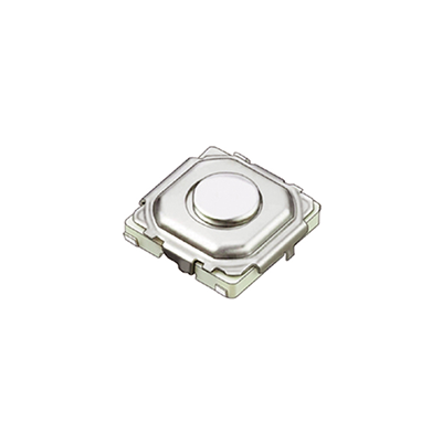
4.9 mm Square SMD Light Touch Switches
Type:
EVQPL/EVQ3PL
EVQ5PL/EVQPT
■ Features
● External dimensions : 4.9 mm× 4.9 mm,
Height: 0.8 mm(Without push plate), 1.5 mm(With push plate)
■ Recommended Applications
● Operation switches for portable electronic equipment
(Notebook PC, Camcorders, Portable audio players, etc.)
● Operation switches for car audio systems
■ Explanation of Part Numbers
1
2
3
Product Code
4
5
6
8
7
Type・Operating Force
9
Product Height
■ Specifications
Type
Snap action/Push-on type SPST
Rating
10 μA 2 V DC to 20 mA 15 V DC (Resistive load)
Contact Resistance
50 mΩ max.
Insulation Resistance
Electrical
50 MΩ min. (at 100 V DC)
Dielectric Withstanding Voltage
250 V AC for 1 minute
3 ms max. (ON)
8 ms max. (OFF)
Bouncing
1.0 N±0.5 N
1.6 N±0.5 N
Operating Force
Mechanical
Travel
Endurance
Operating Life
2.6 N±0.6 N
3.5 N±1.0 N
0.25 mm
+0.10
–0.20
mm
500,000 cycles min.
200,000 cycles min.
–20 °C to +70 °C
Operating Temperature
–40 °C to +85 °C (Bulk)
–20 °C to +60 °C (Taping)
Storage Temperature
Minimum Quantity/Packing Unit
5,000 pcs. Embossed Taping (Reel Pack)
Quantity/Carton
25,000 pcs.
Note: Non washable
Design and specifications are each subject to change without notice. Ask factory for the current technical specifications before purchase and/or use.
Should a safety concern arise regarding this product, please be sure to contact us immediately.
�������
LQGXVWULDO�SDQDVRQLF�FRP�DF�H�
1
© Panasonic Corporation 2019
ANCTB121E 201903-Fd
�Light Touch Switches/EVQPL/3PL/5PL/PT
■ Dimensions in mm (not to scale)
Be careful not to
scratch the film
B
2
φ3.
0.2
4.9
4.6
Surface mount
For reflow soldering
Without push plate
A'
B'
1.2
3.7
4.6
4.9
Operating part
0.4
0.8
(5.5)
(4.6)
4.3
3.1
A
(1)
GND
B
3.4
5.4
(Embossed Taping)
A
0.3
EVQPLF
EVQPLK
EVQ5PL
General dimension tolerance : ± 0.2
( )dimensions are reference dimensions.
0.45
0.05
2.5
5.0±0.5
No. 1
A’
PWB land pattern for reference
Height
0.8 mm
0.8 mm
0.8 mm
B
4
2.
φ
Operating part
Operating Life
500,000 cycles
200,000 cycles
200,000 cycles
General dimension tolerance : ± 0.2
( )dimensions are reference dimensions.
0.45
0.05
(Embossed Taping)
A’
B’
φ
4.
0.4
0.8
1.2
1.5 +– 0.2
0.1
4
(5.5)
(4.6)
4.3
3.1
A
(1)
GND
1.2
3.7
4.6
4.9
B
3.4
5.4
Surface mount
For reflow soldering
With push plate
2.5
5±0.5
0.2
(3.4)
(3.8)
0.3
A
φ2.2
φ4
EVQPLD/PT5
EVQPLH/PT9
EVQPLM
EVQ3PL
Operating Force
1.6 N
2.6 N
3.5 N
4.9
4.6
Part Numbers
EVQPLFA08
EVQPLKA08
EVQ5PLA08
No. 2
B’
Circuit diagram
A’
PWB land pattern for reference
Part Numbers
EVQPLDA15/PT5A15
EVQPLHA15/PT9A15
EVQPLMA15
EVQ3PLA15
Operating Force
1.0 N
1.6 N
2.6 N
3.5 N
B’
Circuit diagram
Height
1.5 mm
1.5 mm
1.5 mm
1.5 mm
Operating Life
500,000/2,000,000 cycles
500,000/2,000,000 cycles
200,000 cycles
200,000 cycles
Design and specifications are each subject to change without notice. Ask factory for the current technical specifications before purchase and/or use.
Should a safety concern arise regarding this product, please be sure to contact us immediately.
Panasonic Corporation Electromechanical Control Business Division
industrial.panasonic.com/ac/e/
2
© Panasonic Corporation 2019
ANCTB121E 201903-Fd
�Light Touch Switches/EVQPL/3PL/5PL/PT
■ Recommended Reflow Soldering Conditions
Operation Top (°C)
MAX.
260
Fan or Normal Temp.
230
180
150
(Normal Temp.)
90±30
40±10
Soldering Time (s)
● Embossed Carrier Taping
Tape width=12.0 mm
t1
Feeding hole
P 2 P0
E
φD0
Chip pocket
B
t2
Chip component
Taping condition : Lack of products in the middle of taping should be
one MAX, but total quantity specified in the
specifications should be secured.
Peeling off strength of top tape : It should be within 0.2N to 1.0N at
165 degree in peeling off angle.
Joint of carrier tape : One joint per one reel may exist.
F
W
A
P1
Tape running direction
Unit: mm
Part No.
EVQPL
EVQ3PL
EVQ5PL
EVQPT
Height
A
B
W
0.8/1.5
5.0±0.2
5.0±0.2
12.0±0.3
F
E
P1
5.5±0.1 1.75±0.10 8.0±0.1
■ Recommended Shape of Test Pole
P2
P0
D0 Dia.
2.0±0.1
4.0±0.1
1.5 –0
+0.1
t1
t2
0.35±0.1 1.0/1.7±0.2
■ Recommended Operating Conditions
for Reflow
soldering
type
0.3 mm max.
Test pole
φ1.0
Leaning angle range
90 °±4 °
(vertical direction)
Switch
Mounting surface
R0.2±0.05
Design and specifications are each subject to change without notice. Ask factory for the current technical specifications before purchase and/or use.
Should a safety concern arise regarding this product, please be sure to contact us immediately.
Panasonic Corporation Electromechanical Control Business Division
industrial.panasonic.com/ac/e/
3
© Panasonic Corporation 2019
ANCTB121E 201903-Fd
�Requests to customers
Please refer to "the latest product specifications" when designing your product.
Requests to customers :
https://industrial.panasonic.com/ac/e/salespolicies/
Safety Precautions
When using our products, no matter what sort of equipment they might be used for, be sure to
confirm the applications and environmental conditions with our specifications in advance.
Please contact ..........
Electromechanical Control Business Division
1006, Oaza Kadoma, Kadoma-shi, Osaka 571-8506, Japan
industrial.panasonic.com/ac/e/
©Panasonic Corporation 2019
ANCTB121E-2 201903-Fd
Specifications are subject to change without notice.
�


 工商网监
湘ICP备2023018690号
工商网监
湘ICP备2023018690号


