Digital Fiber Sensor
85
FX-500 SERIES Ver.2
FIBER
SENSORS
LASER
SENSORS
Related Information
PHOTOELECTRIC
SENSORS
MICRO
PHOTOELECTRIC
SENSORS
AREA
SENSORS
■■General terms and conditions.............. F-3
■■Fiber selection.................................... P.5~
■■Glossary of terms........................ P.1549~
■■Korea’s S-mark.............................. P.1602
■■Selection guide………………………… P.3~
■■SC-GU3......................................... P.971~
■■General precautions.................... P.1552~
Ver.2
Listing
SAFETY LIGHT
CURTAINS /
SAFETY COMPONENTS
PRESSURE /
FLOW
SENSORS
INDUCTIVE
PROXIMITY
SENSORS
Certified
PARTICULAR
USE SENSORS
SENSOR
OPTIONS
SIMPLE
WIRE-SAVING
UNITS
WIRE-SAVING
SYSTEMS
MEASUREMENT
SENSORS
STATIC
CONTROL
DEVICES
LASER
MARKERS
PLC
HUMAN MACHINE
INTERFACES
ENERGY
MANAGEMENT
SOLUTIONS
FA COMPONENTS
*T
� here is no change in Model No. and price due
to version upgrade.
* Cover opened state is shown.
panasonic.net/id/pidsx/global
PNP output
type available
Timer
Automatic
sensitivity setting
Test input
Interference Light intensity
monitor
prevention
External sync.
At the industry’s leading edge
Improved the operability and visibility of the operation keys
Operation keys (setting switch and MODE key) have been renewed to be easy to operate. Also, the color of the keys
has been changed from black to light gray to achieve good visibility in dim light.
Previous
Setting switch
MODE key
Upgraded
(Ver. 2)
MACHINE VISION
SYSTEMS
Setting switch
MODE key
Clicking
touch!
UV CURING
SYSTEMS
Selection
Guide
Fibers
Fiber
Amplifiers
Other Products
FX-500
High stability!
When the FX-500 series is used together with our super quality fiber, the incident light intensity variation among units
is decreased to only 1/4 of that of conventional models.
By being close to absolute values instead of modified digital values, changes in detection that could not be found in
the past can now be monitored.
Super quality fiber
FX-500 series
FX-550
Incident light intensity
Incident light
intensities are
stable.
Threshold Incident light
value
intensity
FX-100
1/4
FX-410
Unify the threshold value
Conventional amplifier
Variation in the threshold value
Can control by
using just one
threshold value.
incident light
intensity variation
[from previous]
Threshold Incident light
value
intensity
Incident light intensity
L
D
MODE
L
D
MODE
L
D
MODE
L
MODE
D
Large variation in
incident
light intensity.
Requires setting
different
threshold values
for each sensor.
�FX-500 SERIES Ver.2
Digital Fiber Sensor
A quality that surpassed that of standard fibers!
86
FIBER
SENSORS
New fibers developed using a new manufacturing method adopted by our own factory along with a persistent quality
control system.
The basic performance of a standard fiber is greatly enhanced!
LASER
SENSORS
PHOTOELECTRIC
SENSORS
MICRO
PHOTOELECTRIC
SENSORS
Expanded temperature range
Ambient temperature [–40 to +70 °C –40 to +158 °F in previous model]
– 55 to +80 °C
– 67 to +176 °F
1.2
times
more than
previous model
Integrated high-precision plug
The centering precision of
the fiber core attached to the
inserting plug is doubled.
As the insertion precision is
increased, the variation among
units can be greatly suppressed.
• Centering precision: within ± 40 μm
SAFETY LIGHT
CURTAINS /
SAFETY COMPONENTS
PRESSURE /
FLOW
SENSORS
INDUCTIVE
PROXIMITY
SENSORS
Previous
Variation in emission amount of the fiber core
is controlled down to less than ±10 %,
achieving a stable detection.
• Beam axis deviation: Thru-beam type within ±2 °,
Reflective type within ±3 °
• Beam axis centering precison: within ± 150 μm
AREA
SENSORS
ø2.2 mm ø0.087 in standard fiber
New material
± 10
Stable emission amount
Single core standard fiber
with high flexibility
In general, high-flexibility
types adopt a multi-fiber core,
which may result in large
variation in light emission.
PARTICULAR
USE SENSORS
R4
More flexible!
SENSOR
OPTIONS
Bending radius [Previous model is R25 mm R0.984 in]
R4 mm
R0.157in
SIMPLE
WIRE-SAVING
UNITS
1/6
of that of
previous model
WIRE-SAVING
SYSTEMS
MEASUREMENT
SENSORS
More bendable!
STATIC
CONTROL
DEVICES
Bending durability [Previous model is 1,000 times]
10 million
times
LASER
MARKERS
10,000 times
more than previous model
PLC
* Bending conditons
Bending radius: R10 mm R 0.394 in,
Reciprocating bending 180°
HUMAN MACHINE
INTERFACES
ENERGY
MANAGEMENT
SOLUTIONS
FA COMPONENTS
H y p e r
Max. 25 μs response time
HYPR mode incorporated
FX-500 with its high response time contributes to
improve productivity.
FX-500 in combination with small diameter fibers which
can handle challenging detections, allows long sensing
range.
7RXJK
FX-500
FD-41
Previous
FD-NFM2
Max.
5.7
Performing minute object detection when using a small
diameter fiber is now possible with a high response time
and longer sensing range.
times! (Note)
Selection
Guide
Fibers
Fiber
Amplifiers
Note: When using FD-NFM2.
Other Products
FX-500
So accurate! Sharp detection with suppressed hysteresis
FX-500 with its
accurate detection
catches fractional
differences in
light intensity, achieving
high precision and
solving low-hysteresis
applications.
• Long range detection of small objects with small
difference in light intensity H-02 mode
FX-550
• Highly accurate detection while
avoiding saturation H-01 mode
FR-Z50HW
Retroreflective
type fiber
FT-A11
Reflector
UV CURING
SYSTEMS
longer than the previous model
HYPR mode
FX-301 (LONG mode)
MACHINE VISION
SYSTEMS
FX-100
FX-410
�87
Digital Fiber Sensor
FIBER
SENSORS
LASER
SENSORS
Flat display with wide viewing angle
The large and high-contrast 7-segment display of high
luminance provides clear visibility from a wide angle of
view.
Pr
ev
i ou
s
sp
ac
e
re
PHOTOELECTRIC
SENSORS
FX-500 SERIES Ver.2
qu
i re
MICRO
PHOTOELECTRIC
SENSORS
SAFETY LIGHT
CURTAINS /
SAFETY COMPONENTS
PRESSURE /
FLOW
SENSORS
INDUCTIVE
PROXIMITY
SENSORS
1/3
nt
Reduced to
me
Compact cover does not get in the way
AREA
SENSORS
of the previous model’s size
Clearly visible even
from sideways
R23 mm
R0.906 in
PARTICULAR
USE SENSORS
SENSOR
OPTIONS
SIMPLE
WIRE-SAVING
UNITS
WIRE-SAVING
SYSTEMS
MEASUREMENT
SENSORS
STATIC
CONTROL
DEVICES
LASER
MARKERS
Resolves variation in displayed incident light intensity
Display adjustment setting
The variation in display can be adjusted to random
values. This helps to define proper instruction in a work
order.
PLC
Current incident light intensity
HUMAN MACHINE
INTERFACES
ENERGY
MANAGEMENT
SOLUTIONS
FA COMPONENTS
MACHINE VISION
SYSTEMS
UV CURING
SYSTEMS
Selection
Guide
Fibers
Fiber
Amplifiers
Other Products
FX-500
FX-550
FX-100
FX-410
Display
adjustment
setting
Unify incident light intensity into any value
Stable detection over long and short periods
Stabilized emission amount
Saves maintenance time
Threshold tracking function
The “four-chemical emitting element”, which we are the
first to incorporate to maintain a stable level of light
emission, has now become an industry standard.
FX-500 series continues to adopt the same emitting
element as well as the “APC (Auto Power Control)
circuit” which improves stability in short periods such as
when the power is turned on.
This function performs automatic setting to threshold
value by checking the incident light intensity at desired
intervals in order to follow the changes in the light
amount resulting from changes in the environment over
long periods (such as dust). This contributes to reduction
in maintenance hours.
Suitable for preventative maintenance FX-502(P)
FX-505(P)-C2
Self-diagnosis output
FX-502(P) / 505(P)-C2 can set Output 2 as a selfdiagnosis output. When the teaching of Output 1’s
threshold value is carried out, Output 2 is set
concurrently with the setting randomly shifted by the
amount of surplus of threshold value. Light intensity
deterioration due to fiber breakage or dust accumulation
can be notified as an alarm output.
�
Detect
deterioration in light intensity
(e.g. Useful in dusty environment)
Self-diagnosis can be used with the threshold
tracking function for added effectiveness.
Stable detection while being eco-friendly
Emission power & gain setting
In cases when the incident
light intensity is saturated,
the light emitting amount
can be adjusted to the
optimal level by AUTO
without changing the
response time. This allows
stable detection with an
optimal S/N ratio and saves
energy by controlling the
emitting electric current.
Detecting a transparent sheet
AUTO
Normal
Object present
Object absent
Saturated
Auto mode (AUTO) and 3-level manual mode (H / M / L [fine-adjustable]) are incorporated.
�Digital Fiber Sensor
FX-500 SERIES Ver.2
Built-in logic functions
No PLC necessary, saving material and programming costs
FIBER
SENSORS
LASER
SENSORS
Logical calculation functions
3 logical calculations (AND, OR,
XOR) are available with fiber
sensor only. 3 logical operations
can be selected against Output 1.
Additional controller is not
required so both wire-saving and
cost reduction can be achieved.
Calculation of two neighboring amplifiers
A
Communication direction (Up to 12 units)
FX-502(P) / 505(P)-C2
ⒶOutput 1: Normal output operation
Detection fiber
Ⓒ Output 1 Calculation result output
Ⓑ Output 2 Normal output operation
Calculation of one amplifier and external input
PHOTOELECTRIC
SENSORS
Truth table
ⒷLower side Output 1: Normal output operation
Calculation result
Ⓒ Lower side Output 1 output
Ⓐ Upper side Output 1 Normal operation
Calculation of two outputs in one amplifier
B
Logical calculation output (C)
AND
OR
XOR
ON
ON
ON
ON
OFF
OFF
ON
OFF
ON
ON
ON
OFF
OFF
ON
ON
OFF
OFF
OFF
OFF
OFF
Analog output cable type
Set to L-ON
Beamreceived
Beaminterrupted
ON
OFF
Sensing
condition
T1
ON-delay
T1
OFF-delay
One-shot
T1
T1
T1
ON/OFF
-delay
T1
ON-delay/
One-shot
T1
T2
T2
ON
OFF
4
ON
OFF
Edge tracking of film or sheet
20
ON
OFF
ON
OFF
Actual position
Meandering position
The number of data banks used for saving the setup
conditions of the amplifirer is increased to eight. Setup
conditions can be saved and loaded to make setup
changes easy at a worksite where multiple models are
manufactured.
WIRE-SAVING
SYSTEMS
MEASUREMENT
SENSORS
STATIC
CONTROL
DEVICES
LASER
MARKERS
PLC
HUMAN MACHINE
INTERFACES
ENERGY
MANAGEMENT
SOLUTIONS
0
Incident light intensity (digit)
FA COMPONENTS
4,000/8,000
MACHINE VISION
SYSTEMS
Timer period: 0.05 ms to 32 s
Output 1 has ON / OFF-delay and ON-delay / One-shot timers are available.
Smooth setup changes by 8 data banks
FX-505(P)-C2
To monitor the sensing of objects, a 4 to 20 mA analog
current is output in respond to the digital value of the
incident light intensity.
Output current (mA)
Time chart
SAFETY LIGHT
CURTAINS /
SAFETY COMPONENTS
PRESSURE /
FLOW
SENSORS
INDUCTIVE
PROXIMITY
SENSORS
SIMPLE
WIRE-SAVING
UNITS
Ⓒ Output 1 Calculation result output
A wide variety of timer control operations
can be carried out by fiber sensors only.
AREA
SENSORS
SENSOR
OPTIONS
External input
Ⓐ (sensor, contact, PLC, etc.)
Equipped with 5 timer types
MICRO
PHOTOELECTRIC
SENSORS
PARTICULAR
USE SENSORS
FX-502(P) / 505(P)-C2
ⒷOutput 1: Normal output operation
Synchronization fiber
88
The meandering path can be monitored
as the light intensity changes.
Remote control improves work
efficiency by external input
FX-502(P)
FX-505(P)-C2
Work efficiency can be improved by operating via PLC
output or other external signal.*
* �FX-502(P) can operate via external signal when switching from Output
2 to external input.
Functions operable by external input
Full-auto * / Limit * /
2-point teaching *
Display adjustment setting *
Data bank load * / save *
Logical calculation (self-unit only)
Emission halt
Copying function lock (self-unit only)
* �FX-505(P)-C2 can obtain answer back output after external input, when
sensing output 2 is set to answer back output mode.
UV CURING
SYSTEMS
Selection
Guide
Fibers
Fiber
Amplifiers
Other Products
FX-500
FX-550
FX-100
FX-410
�89
FIBER
SENSORS
LASER
SENSORS
PHOTOELECTRIC
SENSORS
MICRO
PHOTOELECTRIC
SENSORS
Digital Fiber Sensor
FX-500 SERIES Ver.2
An optical communication function allows
sensors to be adjusted simultaneously
No need to specify a main unit or sub unit
The data that is currently set can be copied and saved all at
once for all amplifiers connected together from the right side
thanks to the optical communication function.
This greatly reduces troublesome setup tasks and makes
setup much smoother.
All FX-500 amplifiers can be used as either a main unit or a
sub unit. Just use a main cable or a sub cable to distinguish
the two. This reduces the costs of inventory management.
AREA
SENSORS
SAFETY LIGHT
CURTAINS /
SAFETY
COMPONENTS
The same part number
can be used as either
a main unit or sub unit!
Single copy & save operation
for all amplifiers
PRESSURE /
FLOW
SENSORS
INDUCTIVE
PROXIMITY
SENSORS
Sub cable
Optical communication
window
PARTICULAR
USE
SENSORS
FX-501□
SENSOR
OPTIONS
SIMPLE
WIRE-SAVING
UNITS
FX-502□
Main cable (3-core)
CN-73-C□
Sub cable (1-core)
CN-71-C□
Main cable (4-core)
CN-74-C□
Sub cable (2-core)
CN-72-C□
Main cable
Disconnection is possible without
moving the amplifier sideways
WIRE-SAVING
SYSTEMS
PLC
HUMAN
MACHINE
INTERFACES
ENERGY
MANAGEMENT
SOLUTIONS
FA
COMPONENTS
MACHINE
VISION
SYSTEMS
UV
CURING
SYSTEMS
Selection
Guide
Fibers
Fiber
Amplifiers
Other
Products
FX-500
FX-550
FX-100
FX-410
Amplifiers Quick-connection cable is not supplied with FX-501(P) and FX-502(P). Please order it separately.
Type
Standard
type
LASER
MARKERS
ORDER GUIDE
2-output type
STATIC
CONTROL
DEVICES
Cable type
MEASUREMENT
SENSORS
Appearance
Model No.
Emitting
element
Output
FX-501
NPN open-collector transistor
FX-501P
PNP open-collector transistor
External input
−
FX-502
NPN open-collector transistor 2 outputs
Red LED
FX-502P
PNP open-collector transistor 2 outputs
FX-505-C2
NPN open-collector transistor 2 outputs
analog output
FX-505P-C2
PNP open-collector transistor 2 outputs
analog output
Incorporated
(Switchable with Output 2)
Incorporated
�Digital Fiber Sensor
FX-500 SERIES Ver.2
ORDER GUIDE
90
FIBER
SENSORS
Quick-connection cables
LASER
SENSORS
For FX-501(P) Quick-connection cable is not supplied with the amplifier. Please order it separately.
PHOTOELECTRIC
SENSORS
Type
Main cable
(3-core)
Sub cable
(1-core)
Model No.
CN-73-C1
Description
CN-73-C5
CN-71-C1
Length: 1 m 3.281 ft
CN-71-C2
CN-71-C5
• CN-73-C□
0.2 mm2 1-core cabtyre cable, with connector
on one end
Length: 2 m 6.562 ft
Cable outer diameter: ø3.3 mm ø0.130 in
Length: 5 m 16.404 ft Connectable to a main cable up to 15 cables.
Sub cable
• CN-71-C□
Main cable
(4-core)
Model No.
CN-74-C1
CN-74-C2
CN-74-C5
Sub cable
(2-core)
CN-72-C1
CN-72-C2
CN-72-C5
Description
Length: 1 m 3.281 ft 0.2 mm2 2-core cabtyre cable, with connector
on one end
Length: 2 m 6.562 ft
Cable outer diameter: ø3.3 mm ø0.130 in
Length: 5 m 16.404 ft Connectable to a main cable up to 15 cables.
Main cable
• CN-74-C□
Model No.
MS-DIN-E
SENSOR
OPTIONS
SIMPLE
WIRE-SAVING
UNITS
WIRE-SAVING
SYSTEMS
Sub cable
• CN-72-C□
MEASUREMENT
SENSORS
STATIC
CONTROL
DEVICES
LASER
MARKERS
End plates End plates are not supplied with the amplifier. Please order them separately when the amplifiers are mounted in cascade.
Appearance
PRESSURE /
FLOW
SENSORS
PARTICULAR
USE
SENSORS
Length: 1 m 3.281 ft
0.2 mm2 4-core cabtyre cable, with connector
Length: 2 m 6.562 ft on one end
Cable outer diameter: ø3.3 mm ø0.130 in
Length: 5 m 16.404 ft
SAFETY LIGHT
CURTAINS /
SAFETY
COMPONENTS
INDUCTIVE
PROXIMITY
SENSORS
For FX-502(P) Quick-connection cable is not supplied with the amplifier. Please order it separately.
Type
MICRO
PHOTOELECTRIC
SENSORS
AREA
SENSORS
Length: 1 m 3.281 ft
0.2 mm2 3-core cabtyre cable, with connector
Length: 2 m 6.562 ft on one end
Cable outer diameter: ø3.3 mm ø0.130 in
Length: 5 m 16.404 ft
CN-73-C2
Main cable
PLC
HUMAN
MACHINE
INTERFACES
Description
ENERGY
MANAGEMENT
SOLUTIONS
When amplifiers are mounted in cascade, or when
an amplifier moves depending on the way it is
installed on a DIN rail, these end plates clamp
amplifiers into place on both sides. Make sure to
use end plates when cascading multiple amplifiers
together.
FA
COMPONENTS
MACHINE
VISION
SYSTEMS
UV
CURING
SYSTEMS
2 pcs. per set
OPTIONS
Designation
Model No.
Amplifier
mounting bracket
MS-DIN-2
Description
Mounting bracket for amplifier
Amplifier mounting bracket
• MS-DIN-2
Selection
Guide
Fibers
Fiber
Amplifiers
Other
Products
FX-500
Accessory
• FX-MB1 (Amplifier protection seal)
10 sets of 2 communication window
seals and 1 connector seal
FX-550
Communication
window seal
FX-100
FX-410
Connector seal
LIST OF FIBERS
Refer to "Fiber Selection p.5 ~" for details of each fiber.
�91
FIBER
SENSORS
Digital Fiber Sensor
SPECIFICATIONS
LASER
SENSORS
MICRO
PHOTOELECTRIC
SENSORS
Type
Model No.
PHOTOELECTRIC
SENSORS
FX-500 SERIES Ver.2
Item
Standard type
2-output type
Cable type (Analog output type)
NPN output
FX-501
FX-502
FX-505-C2
PNP output
FX-501P
FX-502P
FX-505P-C2
EMC Directive, RoHS Directive
CE marking directive compliance
+10
AREA
SENSORS
Supply voltage
SAFETY LIGHT
CURTAINS /
SAFETY
COMPONENTS
Power consumption
Normal operation: 960 mW or less (current consumption 40 mA or less at 24 V supply voltage, excluding analog output of cable type)
ECO mode: 680 mW or less (current consumption 28 mA or less at 24 V supply voltage, excluding analog output of cable type)
Output
(2-output type and cable type:
Output 1, Output 2)
NPN open-collector transistor
PNP open-collector transistor
• Maximum sink current: 100 mA
• Maximum source current: 100 mA
(2-output type and cable type are 50 mA) (Note 2)
(2-output type and cable type are 50 mA) (Note 2)
• Applied voltage: 30 V DC or less (between output and 0 V)
• Applied voltage: 30 V DC or less (between output and +V)
• Residual voltage: 2 V or less (Note 3) (at maximum sink current)
• Residual voltage: 2 V or less (Note 3) (at maximum source current)
PRESSURE /
FLOW
SENSORS
INDUCTIVE
PROXIMITY
SENSORS
PARTICULAR
USE
SENSORS
12 to 24 V DC-15 % Ripple P-P 10 % or less
Output points
1 point
2 points
Output operation
SENSOR
OPTIONS
Switchable either Light-ON or Dark-ON by L/D mode
Short-circuit protection
Incorporated
SIMPLE
WIRE-SAVING
UNITS
Response time
H-SP: 25 μs or less, FAST: 60 μs or less, STD: 250 μs or less, LONG: 2 ms or less, U-LG: 4 ms or less, HYPR: 24 ms or less, selectable
WIRE-SAVING
SYSTEMS
Analog output (Cable type only)
Output current: 4 to 20 mA approx. [H-SP, FAST, STD: At 0 to 4,000 digits, LONG: At 0 to 8,000 digits (Note 4)], Response time: 2 ms or
less, Zero point: Within 4 mA ±1 % F.S., Span: Within 16 mA ±5 % F.S., Linearity: Within ±3 % F.S., Load resistance: 0 to 250 Ω
External input
(2-output type only, switchable
with Output 2)
–
NPN non-contact input
• Signal condition
High: +8 V to +V DC or Open
Low: 0 to +1.2 V DC
(at 0.5 mA source current)
• Input impedance: 10 kΩ approx.
Possible external input function
–
MEASUREMENT
SENSORS
STATIC
CONTROL
DEVICES
LASER
MARKERS
PLC
HUMAN
MACHINE
INTERFACES
ENERGY
MANAGEMENT
SOLUTIONS
FA
COMPONENTS
2-point teaching / Limit teaching / Full-auto teaching / Manual adjustment
Incident light intensity display range
H-SP / FAST / STD: 0 to 4,000, LONG: 0 to 8,000, U-LG / HYPR: 0 to 9,999
Incorporated with variable OFF-delay /
ON-delay / One-shot / ON OFF-delay /
ON-delay • One-shot timer, switchable
either effective or ineffective
Timer function
MACHINE
VISION
SYSTEMS
Fiber
Amplifiers
Other
Products
FX-500
FX-550
FX-100
FX-410
Incorporated with variable OFF-delay / ON-delay / One-shot timer, switchable either
effective or ineffective
Incorporated, 3 levels (each level 25 to 100 %) + Auto setting [1 level (25 to 100 %) when using H-SP mode]
Interference prevention function
Fibers
Incorporated with variable OFF-delay / ON-delay / One-shot / ON OFF-delay /
ON-delay • One-shot timer, switchable either effective or ineffective
Timer range “ms”: 0.5 ms approx., 1 to 9,999 ms approx., 1 ms approx.,
Timer range “sec.”: 0.5 s approx., 1 to 32 s approx., 1 s approx.,
Timer range “1/10 ms”: 0.05 ms approx., 0.1 to 999.9 ms approx., 0.1 ms approx., each output is set individually
Timer period
Light emitting amount selection function
Selection
Guide
Emission halt / Teaching (Full-auto, Limit, 2-point) / Logic operation setting / Copy
lock / Display adjustment / Data bank load / Data bank save, selectable
Sensitivity setting
UV
CURING
SYSTEMS
PNP non-contact input
• Signal condition
High: +4 V to +V DC
(at 3 mA sink current)
Low: 0 to +0.6 V DC or Open
• Input impedance: 10 kΩ approx.
Incorporated (Note 5), selectable either automatic interference prevention or different frequency
Hysteresis setting / Shift amount setting / Emission power setting / Display turning setting / ECO setting / Data bank loading
saving setting / Copying setting / Code setting / Reset setting / Logical calculation setting / Threshold value tracking setting, etc.
Various settings
Protection
IP40 (IEC)
−10 to +55 °C +14 to +131 °F [If 4 to 7 units are mounted in cascade: −10 to +50 °C +14 to +122 °F or if 8 to 16 units (cable type: 8 to 12 units)
are mounted in cascade: −10 to +45 °C +14 to +113 °F] (No dew condensation or icing allowed), Storage: −20 to +70 °C −4 to +158 °F
Ambient temperature
Emitting element (modulated)
Red LED (Peak emission wavelength: 643 nm 0.025 mil)
Material
Enclosure, Case cover: Polycarbonate, Switch: Polyacetal
Cable
–
0.2 mm2 6-core cabtyre cable, 2 m 6.562 ft long
Cable extension
–
Extension up to total 100 m 328.084 ft is
possible with 0.3 mm2, or more, cable.
(however, supply voltage 12 V DC or more)
Net weight: 15 g approx., Gross weight: 70 g approx.
Net weight: 60 g approx., Gross weight: 100 g approx.
Weight
FX-MB1 (Amplifier protection seal): 1 set
Accessory
Notes: 1) Where measurement conditions have not been specified precisely, the conditions used were an ambient temperature of +23 °C +73.4 °F.
2) 50 mA max. if 5 or more standard types are connected together. (25 mA in case of 2-output type and cable type)
3) In case of using the quick-connection cable (cable length 5 m 16.404 ft) (optional).
4) If display adjustment was conducted, it is not in this range.
5) Number of sensor heads which is possible to be mounted closely in auto interference prevention function depends on response time as shown in table below.
Number of sensor heads which is possible to be mounted closely in different frequency Interference prevention function is up to 3 units.
● Number
of sensor heads mountable closely (Unit: set)
Response time H-SP FAST STD LONG U-LG HYPR
IP-1
0
2
4
8
8
12
�Digital Fiber Sensor
FX-500 SERIES Ver.2
I/O CIRCUIT AND WIRING DIAGRAMS
FIBER
SENSORS
FX-501
NPN output type
I/O circuit diagram
Load
(Black) Output
2
+
User’s circuit
Notes: 1) �The quick-connection sub cable does not have +V (brown) and 0 V
(blue). The power is supplied from the connector of the main cable.
2) 50 mA max., if five amplifiers or more, are connected together.
+
12 to 24 V DC
+10
%
-15
Blue (Note 1)
Terminal arrangement diagram
1
+V
2
Output
3
0V
Color code of quick-connection cable
100 mA max. (Note 2)
2
3
+
12 to 24 V DC
+10
%
-15
-
(Black) Output
Load
(Blue) 0 V (Note 1)
Internal circuit
Color code of quick-connection cable
User’s circuit
Notes: 1) �The quick-connection sub cable does not have +V (brown) and 0 V
(blue). The power is supplied from the connector of the main cable.
2) 50 mA max., if five amplifiers or more, are connected together.
Load
Blue (Note 1)
12 to 24 V DC
+10
%
-15
-
Sensor circuit
1
4
PLC
1
+V
2
Output
HUMAN
MACHINE
INTERFACES
3
0V
ENERGY
MANAGEMENT
SOLUTIONS
2
White
Load Load
50 mA max. (Note 2)
(Black) Output 1
50 mA max. (Note 2)
3
+
External
input
Load Load
Black
12 to 24 V DC
+10
%
-15
Blue (Note 1)
+
External
input
User’s circuit
Notes: 1) �The quick-connection sub cable does not have +V (brown) and 0 V
(blue). The power is supplied from the connector of the main cable.
2) 25 mA max., if five amplifiers or more, are connected together.
Terminal arrangement diagram
1
+V
2
Output 1
3
0V
Sensor circuit
1
2
4
3
Terminal No.
4
Output 2 / External input
Brown (Note 1)
(Brown) +V (Note 1)
50 mA max. (Note 2)
(Black) Output 1
50 mA max. (Note 2)
(White) Output 2 / External input
External
input
+
-
Black
12 to 24 V DC
+10
%
-15
Load Load
(Blue) 0 V (Note 1)
User’s circuit
Notes: 1) �The quick-connection sub cable does not have +V (brown) and 0 V
(blue). The power is supplied from the connector of the main cable.
2) 25 mA max., if five amplifiers or more, are connected together.
White
Blue Load Load
(Note 1)
External
input
+
12 to 24 V DC
+10
%
-15
Terminal arrangement diagram
+V
2
Output 1
3
0V
Selection
Guide
Other
Products
FX-550
FX-100
FX-410
Note: T
� he quick-connection sub cable does not have a brown and a blue
lead wire.
1
UV
CURING
SYSTEMS
FX-500
Color code of quick-connection cable
Wiring diagram
Color code of quick-connection cable
MACHINE
VISION
SYSTEMS
Fiber
Amplifiers
PNP output type
I/O circuit diagram
FA
COMPONENTS
Fibers
FX-502P
Internal circuit
12 to 24 V DC
+10
%
-15
Note: T
� he quick-connection sub cable does not have a brown and a blue
lead wire.
(Blue) 0 V (Note 1)
Internal circuit
Color code of quick-connection cable
Brown (Note 1)
(Brown) +V (Note 1)
(White) Output 2 / External input
STATIC
CONTROL
DEVICES
Terminal arrangement diagram
Wiring diagram
Color code of quick-connection cable
MEASUREMENT
SENSORS
LASER
MARKERS
NPN output type
Terminal No.
SIMPLE
WIRE-SAVING
UNITS
Note: T
� he quick-connection sub cable does not have a brown and a blue
lead wire.
FX-502
I/O circuit diagram
PRESSURE /
FLOW
SENSORS
WIRE-SAVING
SYSTEMS
+
Black
SAFETY LIGHT
CURTAINS /
SAFETY
COMPONENTS
SENSOR
OPTIONS
Brown (Note 1)
(Brown) +V (Note 1)
1
Sensor circuit
Wiring diagram
AREA
SENSORS
PARTICULAR
USE
SENSORS
PNP output type
I/O circuit diagram
PHOTOELECTRIC
SENSORS
INDUCTIVE
PROXIMITY
SENSORS
FX-501P
Terminal No.
LASER
SENSORS
MICRO
PHOTOELECTRIC
SENSORS
Note: T
� he quick-connection sub cable does not have a brown and a blue
lead wire.
(Blue) 0 V (Note 1)
Internal circuit
Load
Black
12 to 24 V DC
+10
%
-15
-
100 mA max. (Note 2)
3
Color code of quick-connection cable
Brown (Note 1)
(Brown) +V (Note 1)
1
Sensor circuit
Wiring diagram
Terminal No.
Color code of quick-connection cable
92
4
Output 2 / External input
�93
Digital Fiber Sensor
I/O CIRCUIT AND WIRING DIAGRAMS
FIBER
SENSORS
LASER
SENSORS
PHOTOELECTRIC
SENSORS
FX-505-C2
Wiring diagram
Color code
(Brown) +V
(Pink) External input
Sensor circuit
SAFETY LIGHT
CURTAINS /
SAFETY
COMPONENTS
NPN output type
I/O circuit diagram
MICRO
PHOTOELECTRIC
SENSORS
AREA
SENSORS
FX-500 SERIES Ver.2
Brown
Load
Load
(Black) Output 1
+
-
(White) Output 2
Black
12 to 24 V DC
10
%
15
Internal circuit
+
Pink
(Gray) Analog output (4 to 20 mA)
INDUCTIVE
PROXIMITY
SENSORS
Load
White
(Blue) 0 V
PRESSURE /
FLOW
SENSORS
Load
-
12 to 24 V DC
10
%
15
Blue
Load (0 to 250 Ω)
Load (0 to 250 Ω)
Gray
User’s circuit
PARTICULAR
USE
SENSORS
SENSOR
OPTIONS
SIMPLE
WIRE-SAVING
UNITS
FX-505P-C2
PNP output type
I/O circuit diagram
Wiring diagram
(Brown) +V
MEASUREMENT
SENSORS
(Black) Output 1
STATIC
CONTROL
DEVICES
LASER
MARKERS
Sensor circuit
WIRE-SAVING
SYSTEMS
Brown
+
(White) Output 2
Load
(Pink) External input
(Blue) 0 V
HUMAN
MACHINE
INTERFACES
ENERGY
MANAGEMENT
SOLUTIONS
FA
COMPONENTS
MACHINE
VISION
SYSTEMS
UV
CURING
SYSTEMS
Selection
Guide
Fibers
Fiber
Amplifiers
Other
Products
FX-500
FX-550
FX-100
FX-410
Internal circuit
User’s circuit
-
12 to 24 V DC
10
%
15
Pink
Black
+
White
Load
(Gray) Analog output (4 to 20 mA)
PLC
Color code
Load (0 to 250 Ω)
Blue
Gray
Load
Load
-
12 to 24 V DC
10
%
15
Load (0 to 250 Ω)
�Digital Fiber Sensor
FX-500 SERIES Ver.2
94
SENSING CHARACTERISTICS (TYPICAL)
Thru-beam type Parallel deviation
600
23.622
400
15.748
0
300
11.811
Fiber
head
ℓ
STD
L
Fiber
head
H-SP
200
100
0
100
200
7.874 3.937
3.937 7.874
Left
Center
Right
Operating point ℓ (mm in)
FT-42S
3,000
118.110
STD
1,000
39.370
H-SP
Fiber
head
ℓ
500
19.685
0
2,000
78.740
L
Fiber
head
1,000
0
1,000
39.370
39.370
Left
Center
Right
Operating point ℓ (mm in)
ℓ
H-SP
1,000
39.370
L
Fiber
head
200
0
200
7.874
7.874
Left
Center
Right
Operating point ℓ (mm in)
FT-A11
Fiber
head
L
Fiber
head
H-SP
1,000
500
0
500
1,000
39.370 19.685
19.685 39.370
Left
Center
Right
Operating point ℓ (mm in)
Vertical direction
FTA179
4,000
157.480
4,000
157.480
2,000
78.740
STD
Fiber
head
H-SP
ℓ
1,000
39.370
L
Fiber
head
0
400 300 200 100 0 100 200 300 400
15.748 11.811 7.874 3.937
3.937 7.874 11.811 15.748
Left
Center
Right
Operating point ℓ (mm in)
FTA162
Setting distance L (mm in)
Setting distance L (mm in)
Horizontal direction
FTA185
3,000
118.110
3,000
118.110
2,000
78.740
Fiber
head
H-SP
8mm ℓ
0.315in
L
Fiber
head
0
400 300 200 100
0 100 200 300 400
15.748 11.811 7.874 3.937
3.937 7.874 11.811 15.748
Down
Center
Up
Operating point ℓ (mm in)
FTA162
H-SP
1,000
0
1,000
39.370
39.370
Left
Center
Right
Operating point ℓ (mm in)
STD
1,000
39.370
H-SP
ℓ
Fiber
head
L
Fiber
head
500
19.685
1,000
0
1,000
39.370
39.370
Left
Center
Right
Operating point ℓ (mm in)
FTA183
Horizontal direction
3,000
118.110
H-SP
2,000
78.740
Fiber
head
ℓ
1,000
39.370
0
600
23.622
L
Fiber
head
400
200
0
200
400
15.748 7.874
7.874 15.748
Left
Center
Right
Operating point ℓ (mm in)
FTA217
600
23.622
Thru-beam type
HYPR
SIMPLE
WIRE-SAVING
UNITS
WIRE-SAVING
SYSTEMS
MEASUREMENT
SENSORS
STD
Fiber
head
ℓ
LASER
MARKERS
L
Fiber
head
H-SP
1,000
0
1,000
39.370
39.370
Left
Center
Right
Operating point ℓ (mm in)
STATIC
CONTROL
DEVICES
PLC
2,000
78.740 HUMAN
MACHINE
INTERFACES
Thru-beam type
FTA221
HYPR
ENERGY
MANAGEMENT
SOLUTIONS
FA
COMPONENTS
MACHINE
VISION
SYSTEMS
UV
CURING
SYSTEMS
Fiber
head
ℓ
H-SP
L
Fiber
head
Selection
Guide
1,500 Fibers
59.055
1,000
500
0
500
1,000
39.370 19.685
19.685 39.370
Left
Center
Right
Operating point ℓ (mm in)
Fiber
Amplifiers
Other
Products
Setting distance L (mm in)
Thru-beam type
FTA192
Vertical direction
FX-500
4,000
157.480
FX-100
HYPR
STD
USE
SENSORS
1,000
39.370
0
1,500
59.055
2,000
78.740
600
23.622 PARTICULAR
STD
500
19.685
PRESSURE /
FLOW
SENSORS
INDUCTIVE
PROXIMITY
SENSORS
FTA186
FT-45X
HYPR
L
Fiber
head
SAFETY LIGHT
CURTAINS /
SAFETY
COMPONENTS
SENSOR
OPTIONS
2,000
78.740
1,500
59.055
ℓ
400
200
0
200
400
15.748 7.874
7.874 15.748
Left
Center
Right
Operating point ℓ (mm in)
0
Thru-beam type
FTA224
1,500
59.055
STD
3,500
137.795
3,000
118.110
2,500
98.425
2,000
78.740
1,500
59.055
1,000
39.370
500
19.685
Fiber
head
H-SP
FT-42
2,000
78.740
2,000
78.740
4,000
157.480
STD
L
Fiber
head
FT-A11W
HYPR
1,000
39.370
ℓ
1,000
39.370
0
2,000
78.740
1,500
59.055
Fiber
head
STD
FT-43
Thru-beam type
HYPR
2,000
78.740
2,500
98.425
ℓ
600
23.622
HYPR
0
2,000
78.740
Thru-beam type
STD
0
Thru-beam type
FTA219
3,000
118.110
HYPR
2,000
78.740
1,000
39.370
FT-40
AREA
SENSORS
500
19.685
800 600 400 200 0 200 400 600 800
31.496 23.622 15.748 7.874
7.874 15.748 23.622 31.496
Left
Center
Right
Operating point ℓ (mm in)
400
15.748
3,000
118.110
0
1,500
59.055
2,000
78.740
600
23.622
Fiber
head
L
Fiber
head
0
4,000
157.480
2,000
78.740
4,000
157.480
HYPR
1,500
59.055
STD
FT-42W
Thru-beam type
FTA180
2,000
78.740
3,000
118.110
0
400
15.748
300
11.811
2,500
98.425
HYPR
ℓ
H-SP
Thru-beam type
FTA225
4,000
157.480
STD
Setting distance L (mm in)
800
31.496
Setting distance L (mm in)
Setting distance L (mm in)
HYPR
1,000
39.370
400
200
0
200
400
15.748 7.874
7.874 15.748
Left
Center
Right
Operating point ℓ (mm in)
FT-32
Thru-beam type
FTA187
1,200
47.244
200
7.874
600
23.622
500
19.685
Fiber
head
PHOTOELECTRIC
SENSORS
MICRO
PHOTOELECTRIC
SENSORS
HYPR
1,000
39.370
Setting distance L (mm in)
FT-31W
L
Fiber
head
H-SP
0
1,500
59.055
ℓ
Thru-beam type
1,500
59.055
Setting distance L (mm in)
1,000
500
0
500
1,000
39.370 19.685
19.685 39.370
Left
Center
Right
Operating point ℓ (mm in)
STD
500
19.685
Setting distance L (mm in)
L
Fiber
head
Fiber
head
FT-31S
HYPR
1,000
39.370
Setting distance L (mm in)
ℓ
5,000
196.850
Setting distance L (mm in)
Fiber
head
1,000
39.370
LASER
SENSORS
Thru-beam type
1,500
59.055
HYPR
Setting distance L (mm in)
H-SP
Setting distance L (mm in)
10,000
393.700
Setting distance L (mm in)
Setting distance L (mm in)
STD
FT-31
Thru-beam type
1,500
59.055
HYPR
15,000
590.550
0
1,500
59.055
FT-30
Thru-beam type
20,000
787.400
Sensing characteristics are listed in the alphabetic order of Model No.
Setting distance L (mm in)
FT-140
FIBER
SENSORS
3,000
118.110
HYPR
FX-410
STD
H-SP
2,000
78.740
Fiber
head
8mm ℓ
0.315in
1,000
39.370
0
600
23.622
L
Fiber
head
400
200
0
200
400
15.748 7.874
7.874 15.748
Down
Center
Up
Operating point ℓ (mm in)
FTA217
FX-550
600
23.622
�95
Digital Fiber Sensor
SENSING CHARACTERISTICS (TYPICAL)
FIBER
SENSORS
Horizontal direction
Vertical direction
4,000
157.480
4,000
157.480
4,000
157.480
STD
H-SP
2,000
78.740
Fiber
head
ℓ
1,000
39.370
L
Fiber
head
0
PARTICULAR
USE
SENSORS
300
11.811
200
100
0
100
200
7.874 3.937
3.937 7.874
Left
Center
Right
Operating point ℓ (mm in)
SENSOR
OPTIONS
SIMPLE
WIRE-SAVING
UNITS
WIRE-SAVING
SYSTEMS
PLC
HUMAN
MACHINE
INTERFACES
2,500
98.425
FA
COMPONENTS
Fiber
Amplifiers
19mm ℓ
0.748in
1,000
39.370
Fiber
head
200
100
0
100
200
7.874 3.937
3.937 7.874
Down
Center
Up
Operating point ℓ (mm in)
2,500
98.425
2,000
78.740
1,500
59.055
STD
1,000
39.370
Fiber
head
ℓ
H-SP
500
19.685
L
Fiber
head
1,000
500
0
500
1,000
39.370 19.685
19.685 39.370
Left
Center
Right
Operating point ℓ (mm in)
4,000
157.480
ℓ
L
2,000
78.940
HYPR
STD
H-SP
0
1,000
39.370
Other
Products
1,000
39.370
Fiber
head
200
100
0
100
200
7.874 3.937
3.937 7.874
Left
Center
Right
Operating point ℓ (mm in)
FT-E13
1,500
59.055
STD
Fiber
head
1,000
39.370
500
19.685
H-SP
0
1,500
59.055
36mm
1.417in
500
0
500
19.685
19.685
Left
Center
Right
Operating point ℓ (mm in)
ℓ
L
Fiber
head
1,000
500
0
500
1,000
39.370 19.685
19.685 39.370
Down
Center
Up
Operating point ℓ (mm in)
0
30
1.181
1,500
59.055
FT-H20-J20-S FT-H20-J30-S Thru-beam
type
FT-H20-J50-S FTA215
ℓ
1,500
59.055
HYPR
1,000
39.370
STD
500
19.685
H-SP
0
800
31.496
1,000
39.370
400
0
400
15.748
15.748
Left
Center
Right
Operating point ℓ (mm in)
19mm ℓ
0.748in
0
300
11.811
STD
ℓ
Fiber
head
L
Fiber
head
H-SP
20
10
0
10
20
0.787 0.394
0.394 0.787
Left
Center
Right
Operating point ℓ (mm in)
Fiber
head
200
100
0
100
200
7.874 3.937
3.937 7.874
Down
Center
Up
Operating point ℓ (mm in)
FT-E23
300
11.811
Thru-beam type
FTA218
HYPR
250
9.843
200
7.874
STD
150
5.906
100
3.937
50
1.969
0
150
5.906
30
1.181
L
Fiber
head
ℓ
L
Fiber
head
H-SP
100
50
0
50
100
3.937 1.969
1.969 3.937
Left
Center
Right
Operating point ℓ (mm in)
150
5.906
FT-H20-M1
Thru-beam type
FTA222
2,000
78.740
Fiber
head
L
Fiber
head
Fiber
head
300
11.811
40
1.575
10
0.394
H-SP
1,000
39.370
300
11.811
50
1.969
20
0.787
STD
2,000
78.740
HYPR
30
1.181
HYPR
3,000
118.110
Thru-beam type
FTA218
60
2.362
2,000
78.740
Fiber
head
1,000
39.370
ℓ
L
300
11.811
HYPR
Fiber
head
2,000
78.740
0
300
11.811
2,000
78.740
1,500
59.055
Fiber
head
3,000
118.110
L
H-SP
Vertical direction
Thru-beam type
FTA215
Setting distance L (mm in)
Fibers
Fiber
head
STD
3,000
118.110
Thru-beam type
FTA216
FT-H13-FM2
MACHINE
VISION
SYSTEMS
Selection
Guide
2,000
78.740
300
11.811
HYPR
0
1,500
59.055
ENERGY
MANAGEMENT
SOLUTIONS
UV
CURING
SYSTEMS
H-SP
0
300
11.811
FTA216
Horizontal direction
Setting distance L (mm in)
LASER
MARKERS
STD
FT-AL05
MEASUREMENT
SENSORS
STATIC
CONTROL
DEVICES
3,000
118.110
HYPR
Setting distance L (mm in)
3,000
118.110
HYPR
Setting distance L (mm in)
HYPR
Setting distance L (mm in)
INDUCTIVE
PROXIMITY
SENSORS
Vertical direction
4,000
157.480
Setting distance L (mm in)
PRESSURE /
FLOW
SENSORS
Thru-beam type
Horizontal direction
Setting distance L (mm in)
SAFETY LIGHT
CURTAINS /
SAFETY
COMPONENTS
FT-A32W
Thru-beam type
Setting distance L (mm in)
AREA
SENSORS
FT-A32
Setting distance L (mm in)
MICRO
PHOTOELECTRIC
SENSORS
Sensing characteristics are listed in the alphabetic order of Model No. (Models with same sensing characteristics are grouped together.)
Setting distance L (mm in)
PHOTOELECTRIC
SENSORS
Thru-beam type Parallel deviation
Setting distance L (mm in)
LASER
SENSORS
FX-500 SERIES Ver.2
HYPR
1,500
59.055
STD
1,000
39.370
500
19.685
0
2,000
78.740
800
31.496
FTA223
ℓ
H-SP
Fiber
head
L
Fiber
head
1,000
0
1,000
39.370
39.370
Left
Center
Right
Operating point ℓ (mm in)
2,000
78.740
FX-500
FT-H20-VJ50-S FT-H20-VJ80-S
Horizontal direction
FT-H20W-M1
Thru-beam type
2,000
78.740
Fiber head
HYPR
STD
1,000
39.370
0
400
15.748
H-SP
Fiber
head
ℓ
L
Fiber
head
200
0
200
7.874
7.874
Left
Center
Right
Operating point ℓ (mm in)
400
15.748
ℓ
2,000
78.740
L
Setting distance L (mm in)
2,000
78.740
FT-H30-M1V-S Thru-beam type
Thru-beam type
Vertical direction
Setting distance L (mm in)
FX-410
Setting distance L (mm in)
FX-100
Fiber head
HYPR
STD
1,000
39.370
H-SP
0
400
15.748
200
0
200
7.874
7.874
Down
Center
Up
Operating point ℓ (mm in)
400
15.748
1,500
59.055
HYPR
1,000
39.370
500
19.685
0
800
31.496
Setting distance L (mm in)
FX-550
STD
H-SP
ℓ
Fiber
head
L
Fiber
head
400
0
400
15.748
15.748
Left
Center
Right
Operating point ℓ (mm in)
800
31.496
HYPR
1,000
39.370
STD
500
19.685
H-SP
0
800
31.496
ℓ
Fiber
head
L
Fiber
head
400
0
400
15.748
15.748
Left
Center
Right
Operating point ℓ (mm in)
800
31.496
�FX-500 SERIES Ver.2
Digital Fiber Sensor
96
SENSING CHARACTERISTICS (TYPICAL)
Thru-beam type Parallel deviation
FT-H35-M2
FT-H35-M2S6
Sensing characteristics are listed in the alphabetic order of Model No. (Models with same sensing characteristics are grouped together.)
FT-HL80Y
Thru-beam type
1,000
39.370
STD
ℓ
H-SP
Fiber
head
L
Fiber
head
500
0
500
19.685
19.685
Left
Center
Right
Operating point ℓ (mm in)
3,000
118.110
2,000
78.740
STD
H-SP
1,000
39.370
0
800
31.496
1,000
39.370
Setting distance L (mm in)
HYPR
Thru-beam type
4,000
157.480
HYPR
1,500
59.055
0
1,000
39.370
FT-KS40
Thru-beam type
4,000
157.480
Setting distance L (mm in)
Setting distance L (mm in)
2,000
78.740
500
19.685
FIBER
SENSORS
Fiber
head
ℓ
L
Fiber
head
400
0
400
15.748
15.748
Left
Center
Right
Operating point ℓ (mm in)
FT-KV26
100
3.937
AREA
SENSORS
SAFETY LIGHT
CURTAINS /
SAFETY
COMPONENTS
Fiber
head
H-SP
PRESSURE /
FLOW
SENSORS
ℓ
1,000
39.370
800
31.496
MICRO
PHOTOELECTRIC
SENSORS
STD
2,000
78.740
0
PHOTOELECTRIC
SENSORS
HYPR
3,000
118.110
L
Fiber
head
50
0
50
1.969
1.969
Left
Center
Right
Operating point ℓ (mm in)
INDUCTIVE
PROXIMITY
SENSORS
100
3.937
PARTICULAR
USE
SENSORS
SENSOR
OPTIONS
FT-KV26H1FTA208
Thru-beam type
Thru-beam type
Horizontal direction
Vertical direction
Horizontal direction
Vertical direction
3,000
118.110
3,000
118.110
3,000
118.110
3,000
118.110
1,500
59.055
STD
1,000
39.370
ℓ
H-SP
Fiber
head
L
Fiber
head
500
19.685
0
2,000
78.740
1,500
59.055
1,000
39.370
STD
Fiber
head
H-SP
L
ℓ
500
19.685
Fiber
head
0
HYPR
2,000
78.740
1,500
59.055
STD
1,000
39.370
500
19.685
Fiber
head
ℓ
L
Fiber
head
H-SP
2,500
98.425
STATIC
CONTROL
DEVICES
1,500
59.055
ℓ
Fiber
head
80 60 40 20
0
20 40 60 80
3.150 2.362 1.575 0.787
0.787 1.575 2.362 3.150
Down
Center
Up
Operating point ℓ (mm in)
Thru-beam type
Horizontal direction
Vertical direction
4,000
157.480
4,000
157.480
4,000
157.480
H-SP
ℓ
1,000
39.370
0
100
3.937
Fiber
head
L
Fiber
head
50
0
50
1.969
1.969
Left
Center
Right
Operating point ℓ (mm in)
STD
2,000
78.740
H-SP
1,000
39.370
0
100
3.937
100
3.937
Fiber
head
L
ℓ
Fiber
head
50
0
50
1.969
1.969
Down
Center
Up
Operating point ℓ (mm in)
3,000
118.110
STD
2,000
78.740
H-SP
ℓ
1,000
39.370
0
100
3.937
100
3.937
HYPR
Fiber
head
L
Fiber
head
50
0
50
1.969
1.969
Left
Center
Right
Operating point ℓ (mm in)
100
3.937
Setting distance L (mm in)
2,000
78.740
3,000
118.110
Setting distance L (mm in)
STD
Setting distance L (mm in)
Setting distance L (mm in)
Vertical direction
4,000
157.480
3,000
118.110
LASER
MARKERS
L
H-SP
FT-KV40W
HYPR
Fiber
head
STD
1,000
39.370
Horizontal direction
HYPR
MEASUREMENT
SENSORS
HYPR
2,000
78.740
500
19.685
HUMAN
MACHINE
INTERFACES
ENERGY
MANAGEMENT
SOLUTIONS
FA
COMPONENTS
UV
CURING
SYSTEMS
HYPR
STD
2,000
78.740
H-SP
Fiber
head
1,000
39.370
100
3.937
PLC
MACHINE
VISION
SYSTEMS
3,000
118.110
0
SIMPLE
WIRE-SAVING
UNITS
WIRE-SAVING
SYSTEMS
0
80 60 40 20
0
20 40 60 80
3.150 2.362 1.575 0.787
0.787 1.575 2.362 3.150
Left
Center
Right
Operating point ℓ (mm in)
Thru-beam type
FTA209
FTA209
2,500
98.425
0
80 60 40 20
0
20 40 60 80
3.150 2.362 1.575 0.787
0.787 1.575 2.362 3.150
Down
Center
Up
Operating point ℓ (mm in)
80 60 40 20
0
20 40 60 80
3.150 2.362 1.575 0.787
0.787 1.575 2.362 3.150
Left
Center
Right
Operating point ℓ (mm in)
FT-KV40
2,500
98.425
Setting distance L (mm in)
2,000
78.740
HYPR
Setting distance L (mm in)
Setting distance L (mm in)
2,500
98.425
Setting distance L (mm in)
HYPR
LASER
SENSORS
L
ℓ
Fiber
head
50
0
50
1.969
1.969
Down
Center
Up
Operating point ℓ (mm in)
Selection
Guide
Fibers
Fiber
Amplifiers
100 Other
3.937 Products
FX-500
FT-L80Y
FT-R31
Thru-beam type
FTA205
1,200
47.244
2,000
78.740
1,000
39.370
0
800
31.496
STD
H-SP
ℓ
Fiber
head
L
Fiber
head
400
0
400
15.748
15.748
Left
Center
Right
Operating point ℓ (mm in)
800
31.496
1,000
39.370
HYPR
800
31.496
600
23.622
400
15.748
200
7.874
0
600
23.622
STD
H-SP
Fiber
head
ℓ
L
Fiber
head
400
200
0
200
400
15.748 7.874
7.874 15.748
Left
Center
Right
Operating point ℓ (mm in)
600
23.622
Thru-beam type
FTA206
HYPR
3,000
118.110
2,000
78.740
1,000
39.370
0
1,500
59.055
FX-550
FTA206
FX-100
FX-410
4,000
157.480
Setting distance L (mm in)
HYPR
Setting distance L (mm in)
Setting distance L (mm in)
4,000
157.480
3,000
118.110
FT-R40
Thru-beam type
FTA205
STD
H-SP
Fiber
head
ℓ
L
Fiber
head
1,000
500
0
500
1,000
39.370 19.685
19.685 39.370
Left
Center
Right
Operating point ℓ (mm in)
1,500
59.055
�97
Digital Fiber Sensor
SENSING CHARACTERISTICS (TYPICAL)
INDUCTIVE
PROXIMITY
SENSORS
3,500
137.795
3,000
118.110
2,500
98.425
2,000
78.740
1,500
59.055
0 1,500
59.055
SENSOR
OPTIONS
Fiber
head
STD
1,000
39.370
500
19.685
PARTICULAR
USE
SENSORS
SIMPLE
WIRE-SAVING
UNITS
HYPR
ℓ
H-SP
L
Fiber
head
1,000
500
0
500
1,000
39.370 19.685
19.685 39.370
Left
Center
Right
Operating point ℓ (mm in)
FT-R43
0 1,500
59.055
FTA193
Thru-beam type
PLC
HUMAN
MACHINE
INTERFACES
Fiber
head
STD
1,000
39.370
500
19.685
0 1,500
59.055
ENERGY
MANAGEMENT
SOLUTIONS
HYPR
ℓ
L
H-SP
Fiber
head
1,000
500
0
500
1,000
39.370 19.685
19.685 39.370
Left
Center
Right
Operating point ℓ (mm in)
0 1,500
59.055
1,500
59.055
L
Fiber
head
1,000
500
0
500
1,000
39.370 19.685
19.685 39.370
Down
Center
Up
Operating point ℓ (mm in)
3,500
137.795
3,000
118.110
2,500
98.425
2,000
78.740
1,500
59.055
1,000
39.370
500
19.685
ℓ
H-SP
FT-R44Y
Setting distance L (mm in)
LASER
MARKERS
Setting distance L (mm in)
STATIC
CONTROL
DEVICES
3,500
137.795
3,000
118.110
2,500
98.425
2,000
78.740
1,500
59.055
Fiber
head
STD
WIRE-SAVING
SYSTEMS
MEASUREMENT
SENSORS
4,000
157.480
HYPR
1,000
39.370
500
19.685
1,500
59.055
Horizontal direction
4,000
157.480
HYPR
STD
3,000
118.110
2,000
78.740
Fiber
head
H-SP
1,000
39.370
0
1,000
39.370
1,500
59.055
ℓ
L
Fiber
head
500
0
500
19.685
19.685
Left
Center
Right
Operating point ℓ (mm in)
Fiber
head
ℓ
H-SP
L
Fiber
head
1,000
500
0
500
1,000
39.370 19.685
19.685 39.370
Left
Center
Right
Operating point ℓ (mm in)
STD
3,000
118.110
2,000
78.740
0
1,000
39.370
Fiber
head
H-SP
1,000
39.370
1,000
39.370
ℓ
L
Fiber
head
500
0
500
19.685
19.685
Down
Center
Up
Operating point ℓ (mm in)
1,000
39.370
FTA194
Thru-beam type
FT-S11
FTA194
Thru-beam type
4,000
157.480
HYPR
400
15.748
HYPR
3,000
118.110
STD
HYPR
FT-R60Y
Thru-beam type
FTA193
HYPR
Vertical direction
Setting distance L (mm in)
PRESSURE /
FLOW
SENSORS
Vertical direction
3,500
137.795
3,000
118.110
2,500
98.425
2,000
78.740
1,500
59.055
Thru-beam type
Setting distance L (mm in)
SAFETY LIGHT
CURTAINS /
SAFETY
COMPONENTS
Horizontal direction
Setting distance L (mm in)
AREA
SENSORS
FT-R42W
Thru-beam type
Setting distance L (mm in)
MICRO
PHOTOELECTRIC
SENSORS
Sensing characteristics are listed in the alphabetic order of Model No.
FT-R41W
Setting distance L (mm in)
PHOTOELECTRIC
SENSORS
Thru-beam type Parallel deviation
Setting distance L (mm in)
FIBER
SENSORS
LASER
SENSORS
FX-500 SERIES Ver.2
2,000
78.740
1,000
39.370
0
1,000
39.370
1,500
59.055
Fiber
head
STD
ℓ
H-SP
L
Fiber
head
500
0
500
19.685
19.685
Left
Center
Right
Operating point ℓ (mm in)
300
11.811
200
7.874
100
3.937
0
1,000
39.370
150
5.906
STD
Fiber
head
ℓ
L
H-SP
Fiber
head
100
50
0
50
100
3.937 1.969
1.969 3.937
Left
Center
Right
Operating point ℓ (mm in)
150
5.906
FA
COMPONENTS
1,000
39.370
Selection
Guide
Fibers
Fiber
Amplifiers
Other
Products
500
19.685
ℓ
L
H-SP
0
600
23.622
FX-500
Fiber
head
STD
Fiber
head
400
200
0
200
400
15.748 7.874
7.874 15.748
Left
Center
Right
Operating point ℓ (mm in)
1,200
47.244
HYPR
1,000
39.370
Fiber
head
500
19.685
STD
ℓ
L
H-SP
Fiber
head
600
23.622
STD
ℓ
L
H-SP
Fiber
head
200
100
0
100
200
7.874 3.937
3.937 7.874
Left
Center
Right
Operating point ℓ (mm in)
300
11.811
FX-550
FT-S30
FT-S31W
Thru-beam type
FTA227
FX-410
Thru-beam type
FT-S32
FTA220
4,000
157.480
HYPR
2,000
78.740
0
2,000
78.740
4,000
157.480
HYPR
3,000
118.110
3,000
118.110
3,000
118.110
1,000
39.370
Setting distance L (mm in)
Setting distance L (mm in)
4,000
157.480
Setting distance L (mm in)
FX-100
Fiber
head
STD
ℓ
H-SP
L
Fiber
head
1,000
0
1,000
39.370
39.370
Left
Center
Right
Operating point ℓ (mm in)
2,000
78.740
2,000
78.740
1,000
39.370
0
1,500
59.055
STD
H-SP
ℓ
Fiber
head
L
Fiber
head
1,000
500
0
500
1,000
39.370 19.685
19.685 39.370
Left
Center
Right
Operating point ℓ (mm in)
1,500
59.055
2,000
78.740
1,000
39.370
0
1,000
39.370
HYPR
800
31.496
Fiber
head
400
15.748
0
300
11.811
Thru-beam type
FTA178
1,200
47.244
800
31.496
200
7.874
FT-S22
1,600
62.992
HYPR
1,000
39.370
0
800 600 400 200 0 200 400 600 800
31.496 23.622 15.748 7.874
7.874 15.748 23.622 31.496
Left
Center
Right
Operating point ℓ (mm in)
600
23.622
Thru-beam type
FTA226
Setting distance L (mm in)
1,500
59.055
HYPR
FT-S21W
Thru-beam type
Setting distance L (mm in)
1,500
59.055
FT-S21
Thru-beam type
Setting distance L (mm in)
UV
CURING
SYSTEMS
FT-S20
Setting distance L (mm in)
MACHINE
VISION
SYSTEMS
Thru-beam type
FTA182
HYPR
STD
H-SP
ℓ
Fiber
head
L
Fiber
head
500
0
500
19.685
19.685
Left
Center
Right
Operating point ℓ (mm in)
1,000
39.370
ℓ
400
15.748
L
H-SP
0
100
3.937
Fiber
head
STD
Fiber
head
50
0
50
1.969
1.969
Left
Center
Right
Operating point ℓ (mm in)
100
3.937
�FX-500 SERIES Ver.2
Digital Fiber Sensor
98
SENSING CHARACTERISTICS (TYPICAL)
Sensing characteristics are listed in the alphabetic order of Model No.
2,000
78.740
ℓ
H-SP
FT-V25
L
Fiber
head
500
19.685
Fiber
head
Vertical direction
1,000
39.370
L
Fiber
head
200
100
0
100
200
7.874 3.937
3.937 7.874
Left
Center
Right
Operating point ℓ (mm in)
FT-V40
Setting distance L (mm in)
300
11.811
STD
2,000
78.740
H-SP
ℓ
L
Fiber
head
200
100
0
100
200
7.874 3.937
3.937 7.874
Left
Center
Right
Operating point ℓ (mm in)
300
11.811
H-SP
HYPR
1,000
39.370
0
300
11.811
L
Fiber
head
200
100
0
100
200
7.874 3.937
3.937 7.874
Down
Center
Up
Operating point ℓ (mm in)
FT-Z20W
600
23.622
STD
H-SP
ℓ
L
Fiber
head
400
200
0
200
400
15.748 7.874
7.874 15.748
Left
Center
Right
Operating point ℓ (mm in)
600
23.622
500
0
500
19.685
19.685
Left
Center
Right
Operating point ℓ (mm in)
FT-V80Y
0
1,000
39.370
1,000
39.370
SENSOR
OPTIONS
SIMPLE
WIRE-SAVING
UNITS
WIRE-SAVING
SYSTEMS
MEASUREMENT
SENSORS
STATIC
CONTROL
DEVICES
STD
Fiber
head
ℓ
LASER
MARKERS
PLC
L
H-SP
HUMAN
MACHINE
INTERFACES
Fiber
head
500
0
500
19.685
19.685
Down
Center
Up
Operating point ℓ (mm in)
1,000
39.370 ENERGY
MANAGEMENT
SOLUTIONS
FTA191
Thru-beam type
FTA191
Vertical direction
4,000
157.480
HYPR
3,000
118.110
STD
2,000
78.740
1,000
39.370
0
800
31.496
Fiber head
ℓ
H-SP
L
Fiber head
400
0
400
15.748
15.748
Left
Center
Right
Operating point ℓ (mm in)
800
31.496
Thru-beam type
2,000
78.740
HYPR
1,500
59.055
STD
1,000
39.370
Fiber
head
ℓ
L
Fiber
head
400 300 200 100 0 100 200 300 400
15.748 11.811 7.874 3.937
3.937 7.874 11.811 15.748
Left
Center
Right
Operating point ℓ (mm in)
FTA294
500
19.685
PARTICULAR
USE
SENSORS
2,000
78.740
1,000
39.370
0
800
31.496
MACHINE
VISION
SYSTEMS
UV
CURING
SYSTEMS
HYPR
STD
Selection
Guide
H-SP
Fibers
Fiber head
ℓ
Fiber
Amplifiers
L
Other
Products
Fiber head
400
0
400
15.748
15.748
Down
Center
Up
Operating point ℓ (mm in)
800
31.496
FX-500
FX-550
HYPR
0
200
7.874
HYPR
1,000
39.370
Fiber
head
L
Fiber
head
2,000
78.740
H-SP
Fiber
head
100
0
100
3.937
3.937
Down
Center
Up
Operating point ℓ (mm in)
1,500
59.055
ℓ
Vertical direction
500
19.685
INDUCTIVE
PROXIMITY
SENSORS
L
H-SP
2,500
98.425
H-SP
FTA207
STD
PRESSURE /
FLOW
SENSORS
Fiber
head
ℓ
Vertical direction
STD
Horizontal direction
1,000
39.370
Fiber
head
STD
FA
COMPONENTS
300
11.811
1,500
59.055
800
31.496
200
7.874
SAFETY LIGHT
CURTAINS /
SAFETY
COMPONENTS
2,000
78.740
3,000
118.110
ℓ
AREA
SENSORS
FTA188
Thru-beam type
HYPR
4,000
157.480
Fiber
head
0
200
7.874
Horizontal direction
HYPR
2,000
78.740
Setting distance L (mm in)
Setting distance L (mm in)
200
100
0
100
200
7.874 3.937
3.937 7.874
Down
Center
Up
Operating point ℓ (mm in)
HYPR
FTA188
1,000
39.370
0
1,000
39.370
200
7.874
100
3.937
L
Fiber
head
100
0
100
3.937
3.937
Left
Center
Right
Operating point ℓ (mm in)
FT-V30
500
19.685
Fiber
head
STD
300
11.811
1,000
39.370
600
23.622
L
3,000
118.110
Thru-beam type
FT-Z20HBWFTA207
0
ℓ
H-SP
4,000
157.480
1,000
39.370
200
7.874
Fiber
head
Vertical direction
Fiber
head
H-SP
1,500
59.055
STD
FTA189
3,000
118.110
ℓ
2,500
98.425
FTA189
Thru-beam type
HYPR
1,200
47.244
200
7.874
0
300
11.811
Horizontal direction
4,000
157.480
Setting distance L (mm in)
H-SP
Setting distance L (mm in)
Setting distance L (mm in)
ℓ
200
7.874
Fiber
head
2,000
78.740
400
15.748
Fiber
head
100
3.937
200
7.874
HYPR
600
23.622
400
15.748
STD
PHOTOELECTRIC
SENSORS
MICRO
PHOTOELECTRIC
SENSORS
300
11.811
Horizontal direction
800
31.496
STD
400
15.748
200
7.874
0
0
800 600 400 200 0 200 400 600 800
31.496 23.622 15.748 7.874
7.874 15.748 23.622 31.496
Down
Center
Up
Operating point ℓ (mm in)
HYPR
600
23.622
400
15.748
L
H-SP
FTA190
Thru-beam type
800
31.496
300
11.811
Fiber
head
ℓ
FTA190
Horizontal direction
1,000
39.370
STD
Vertical direction
HYPR
300
11.811
1,000
39.370
Fiber
head
0
800 600 400 200 0 200 400 600 800
31.496 23.622 15.748 7.874
7.874 15.748 23.622 31.496
Left
Center
Right
Operating point ℓ (mm in)
0
HYPR
Setting distance L (mm in)
STD
500
19.685
300
11.811
400
15.748
1,500
59.055
1,000
39.370
0
Horizontal direction
Setting distance L (mm in)
Setting distance L (mm in)
HYPR
1,500
59.055
Thru-beam type
Setting distance L (mm in)
Vertical direction
Setting distance L (mm in)
2,000
78.740
Setting distance L (mm in)
Horizontal direction
FT-V24W
Setting distance L (mm in)
Thru-beam type
LASER
SENSORS
Setting distance L (mm in)
FT-V23
Setting distance L (mm in)
Thru-beam type Parallel deviation
FIBER
SENSORS
500
19.685
0
H-SP
Fiber
head
1.2mm
0.047in
ℓ
L
Fiber
head
400 300 200 100 0 100 200 300 400
15.748 11.811 7.874 3.937
3.937 7.874 11.811 15.748
Down
Center
Up
Operating point ℓ (mm in)
FX-100
FX-410
�99
SENSING CHARACTERISTICS (TYPICAL)
LASER
MARKERS
PLC
4,000
157.480
2,000
78.740
400
15.748
ENERGY
MANAGEMENT
SOLUTIONS
MACHINE
VISION
SYSTEMS
UV
CURING
SYSTEMS
Selection
Guide
Fibers
Fiber
Amplifiers
0
400
15.748
Fiber
head
ℓ
L
Fiber
head
200
0
200
7.874
7.874
Left
Center
Right
Operating point ℓ (mm in)
2,000
78.740
1,000
39.370
0
400
15.748
400
15.748
ℓ
L
Fiber
head
200
0
200
7.874
7.874
Left
Center
Right
Operating point ℓ (mm in)
ℓ
L
5.5mm
0.217in
Fiber
head
200
0
200
7.874
7.874
Down
Center
Up
Operating point ℓ (mm in)
1,000
39.370
STD
2,000
78.740
1,000
39.370
Fiber
head
ℓ
L
H-SP
Fiber
head
0
800 600 400 200 0 200 400 600 800
31.496 23.622 15.748 7.874
7.874 15.748 23.622 31.496
Left
Center
Right
Operating point ℓ (mm in)
FTA295
1,000
39.370
ℓ
Fiber
head
L
Fiber
head
STD
H-SP
Fiber
head
1.2mm
0.047in
ℓ
L
Thru-beam type
FTA199
Fiber
head
0
800 600 400 200 0 200 400 600 800
31.496 23.622 15.748 7.874
7.874 15.748 23.622 31.496
Down
Center
Up
Operating point ℓ (mm in)
FTA295
Fiber
head
STD
0
1,500
59.055
ℓ
L
Fiber
head
1,000
500
0
500
1,000
39.370 19.685
19.685 39.370
Left
Center
Right
Operating point ℓ (mm in)
FTA204
1,500
59.055
H-SP
2,000
78.740
1,000
39.370
0
800
31.496
ℓ
Fiber
head
L
5.5mm
0.217in
Fiber
head
500
0
500
19.685
19.685
Down
Center
Up
Operating point ℓ (mm in)
FT-Z802Y
3,000
118.110
H-SP
STD
1,000
39.370
4,000
157.480
HYPR
2,000
78.740
1,000
39.370
400
15.748
HYPR
2,000
78.740
0
1,000
39.370
1,000
39.370
3,000
118.110
2,000
78.740
Fiber
head
200
0
200
7.874
7.874
Down
Center
Up
Operating point ℓ (mm in)
3,000
118.110
500
0
500
19.685
19.685
Left
Center
Right
Operating point ℓ (mm in)
4,000
157.480
L
5.5mm
0.217in
4,000
157.480
2.2mm
0.087in
4,000
157.480
3,000
118.110
400
15.748
ℓ
Vertical direction
H-SP
4,000
157.480
3,000
118.110
1,000
39.370
0
Fiber
head
H-SP
Thru-beam type
FTA201
STD
FT-Z40HBW
HYPR
STD
2,000
78.740
400
15.748
HYPR
2,000
78.740
0
1,000
39.370
400
15.748
300
11.811
HYPR
FT-Z30W FTA201
Thru-beam type
FTA202
Vertical direction
HYPR
Fiber
head
H-SP
FTA202
Horizontal direction
FT-Z40W
Setting distance L (mm in)
Setting distance L (mm in)
400
15.748
Fiber
head
200
100
0
100
200
7.874 3.937
3.937 7.874
Down
Center
Up
Operating point ℓ (mm in)
3,000
118.110
STD
3,000
118.110
Fiber
head
300
11.811
4,000
157.480
HYPR
4,000
157.480
H-SP
0
L
5.5mm
0.217in
FTA163
Vertical direction
1,000
39.370
0
Fiber
ℓ head
H-SP
1,000
39.370
300
11.811
Horizontal direction
STD
2,000
78.740
Thru-beam type
2,000
78.740
400
15.748
HYPR
3,000
118.110
H-SP
1,000
39.370
Fiber
head
200
0
200
7.874
7.874
Down
Center
Up
Operating point ℓ (mm in)
FTA200
Thru-beam type
STD
2,000
78.740
L
5.5mm
0.217in
4,000
157.480
Setting distance L (mm in)
FX-410
1,000
39.370
400
15.748
Fiber
ℓ head
H-SP
STD
FT-Z30H
3,000
118.110
STD
2,000
78.740
0
400
15.748
HYPR
200
100
0
100
200
7.874 3.937
3.937 7.874
Left
Center
Right
Operating point ℓ (mm in)
4,000
157.480
HYPR
Vertical direction
3,000
118.110
300
11.811
L
Fiber
head
4,000
157.480
4,000
157.480
FX-500
FX-100
200
0
200
7.874
7.874
Left
Center
Right
Operating point ℓ (mm in)
ℓ
1,000
39.370
0
1,000
39.370
Fiber
head
H-SP
FTA163
Horizontal direction
FTA200
Horizontal direction
Other
Products
FX-550
L
Fiber
head
Fiber
head
500
0
500
19.685
19.685
Down
Center
Up
Operating point ℓ (mm in)
FT-Z30HW
Setting distance L (mm in)
FA
COMPONENTS
ℓ
1,000
39.370
0
Fiber
head
H-SP
L
5.5mm
0.217in
3,000
118.110
STD
ℓ
2,000
78.740
Thru-beam type
FTA198
Vertical direction
HYPR
3,000
118.110
HUMAN
MACHINE
INTERFACES
0
1,000
39.370
1,000
39.370
FTA198
Horizontal direction
1,000
39.370
Fiber
head
Setting distance L (mm in)
STATIC
CONTROL
DEVICES
Fiber
head
500
0
500
19.685
19.685
Left
Center
Right
Operating point ℓ (mm in)
H-SP
HYPR
3,000
118.110
STD
Setting distance L (mm in)
MEASUREMENT
SENSORS
L
FT-Z30EW
Setting distance L (mm in)
WIRE-SAVING
SYSTEMS
2.2mm
0.087in
2,000
78.740
4,000
157.480
HYPR
3,000
118.110
STD
Vertical direction
Setting distance L (mm in)
SENSOR
OPTIONS
Fiber
head
ℓ
1,000
39.370
HYPR
3,000
118.110
H-SP
4,000
157.480
Setting distance L (mm in)
2,000
78.740
0
1,000
39.370
PARTICULAR
USE
SENSORS
SIMPLE
WIRE-SAVING
UNITS
STD
3,000
118.110
Thru-beam type
Horizontal direction
Setting distance L (mm in)
INDUCTIVE
PROXIMITY
SENSORS
HYPR
Setting distance L (mm in)
PRESSURE /
FLOW
SENSORS
4,000
157.480
Setting distance L (mm in)
SAFETY LIGHT
CURTAINS /
SAFETY
COMPONENTS
Vertical direction
Setting distance L (mm in)
AREA
SENSORS
Horizontal direction
4,000
157.480
FT-Z30E
Thru-beam type
Setting distance L (mm in)
MICRO
PHOTOELECTRIC
SENSORS
Sensing characteristics are listed in the alphabetic order of Model No.
FT-Z30
Setting distance L (mm in)
PHOTOELECTRIC
SENSORS
Thru-beam type Parallel deviation
Setting distance L (mm in)
FIBER
SENSORS
LASER
SENSORS
FX-500 SERIES Ver.2
Digital Fiber Sensor
1,000
39.370
Thru-beam type
FTA199
HYPR
STD
H-SP
ℓ
Fiber
head
L
Fiber
head
400
0
400
15.748
15.748
Left
Center
Right
Operating point ℓ (mm in)
800
31.496
�FX-500 SERIES Ver.2
Digital Fiber Sensor
100
SENSING CHARACTERISTICS (TYPICAL)
FR-KZ22E
Vertical direction
600
23.622
HYPR
HYPR
500
19.685
300
11.811
200
7.874
H-SP
ℓ
L
100
3.937
Fiber
head
0
20
0.787
10
0
10
0.394
0.394
Left
Center
Right
Operating point ℓ (mm in)
200
7.874
H-SP
HYPR
L
20
0.787
10
0
10
0.394
0.394
Down
Center
Up
Operating point ℓ (mm in)
H-SP
1,200
47.244
1,200
47.244
HYPR
0
10
0.394
5
0
5
0.197
0.197
Left
Center
Right
Operating point ℓ (mm in)
Setting distance L (mm in)
600
23.622
STD
400
15.748
H-SP
200
7.874
0
10
0.394
10
0.394
STD
400
15.748
H-SP
Reflector
RF-003
ℓ
L
200
7.874
Fiber
head
0
20
0.787
Fiber
head
5
0
5
0.197
0.197
Down
Center
Up
Operating point ℓ (mm in)
FRA012
10
0
10
0.394
0.394
Left
Center
Right
Operating point ℓ (mm in)
600
23.622
STD
400
15.748
H-SP
20
0.787
20
0.787
L
PLC
Fiber
head
10
0
10
0.394
0.394
Down
Center
Up
Operating point ℓ (mm in)
HUMAN
MACHINE
INTERFACES
20
0.787
Retroreflective type
H-SP
500
19.685
Reflective tape
RF-13
ℓ
L
Fiber
head
100
50
0
50
100
3.937 1.969
1.969 3.937
Left
Center
Right
Operating point ℓ (mm in)
Reflective type Sensing field
HYPR
1,500
59.055
STD
3,000
118.110
STD
2,000
78.740
H-SP
1,000
39.370
H-SP
500
19.685
100
50
0
50
100
3.937 1.969
1.969 3.937
Down
Center
Up
Operating point ℓ (mm in)
800
31.496
400
15.748
150
5.906
White
non-glossy paper
ℓ
L
Fiber
head
H-SP
Left
Right
100
50
0
50
100
3.937 1.969
1.969 3.937
Left
Center
Right
Operating point ℓ (mm in)
150
5.906
Setting distance L (mm in)
Setting distance L (mm in)
Vertical direction
600
23.622
Reflector
RF-230
ℓ
1,000
39.370
L
Fiber
head
STD
2,000
78.740
H-SP
Selection
Guide
L
Fiber
head
0
400 300 200 100 0 100 200 300 400
15.748 11.811 7.874 3.937
3.937 7.874 11.811 15.748
Down
Center
Up
Operating point ℓ (mm in)
600
23.622
HYPR
150
5.906
Vertical direction
600
23.622
400
15.748
400
15.748
STD
H-SP
White
non-glossy paper
ℓ
L
Fiber
head
Up
Down
100
50
0
50
100
3.937 1.969
1.969 3.937
Down
Center
Up
Operating point ℓ (mm in)
150
5.906
STD
300
11.811
200
7.874
100
3.937
0
150
5.906
HYPR
500
19.685
500
19.685
400
15.748
0
FRA011
HYPR
L
Fiber
head
H-SP
Left
Right
100
50
0
50
100
3.937 1.969
1.969 3.937
Left
Center
Right
Operating point ℓ (mm in)
STD
300
11.811
White
non-glossy paper
ℓ
150
5.906
Fibers
Fiber
Amplifiers
Other
Products
FX-500
FX-550
FRA011
Reflective type
Horizontal direction
600
23.622
200
7.874
FD-31
FA
COMPONENTS
UV
CURING
SYSTEMS
Reflector
RF-230
ℓ
1,000
39.370
ENERGY
MANAGEMENT
SOLUTIONS
MACHINE
VISION
SYSTEMS
HYPR
3,000
118.110
0
400 300 200 100 0 100 200 300 400
15.748 11.811 7.874 3.937
3.937 7.874 11.811 15.748
Left
Center
Right
Operating point ℓ (mm in)
150
5.906
FRA010
Reflective type
HYPR
STD
Reflective tape
RF-13
ℓ
L
Fiber
head
FD-30
800
31.496
HYPR
4,000
157.480
4,000
157.480
Sensing characteristics are listed in the alphabetic order of the Model No.
FRA010
Horizontal direction
Vertical direction
2,000
78.740
0
150
5.906
150
5.906
With reflector RF-230 (optional)
Horizontal direction
Setting distance L (mm in)
1,000
39.370
0
SIMPLE
WIRE-SAVING
UNITS
LASER
MARKERS
Setting distance L (mm in)
STD
PARTICULAR
USE
SENSORS
SENSOR
OPTIONS
Reflector
RF-003
ℓ
Setting distance L (mm in)
1,500
59.055
INDUCTIVE
PROXIMITY
SENSORS
STATIC
CONTROL
DEVICES
Setting distance L (mm in)
HYPR
Setting distance L (mm in)
Setting distance L (mm in)
2,000
78.740
PRESSURE /
FLOW
SENSORS
MEASUREMENT
SENSORS
200
7.874
0
SAFETY LIGHT
CURTAINS /
SAFETY
COMPONENTS
WIRE-SAVING
SYSTEMS
FRA013
With reflective tape RF-13 (attached)
FRA013
Horizontal direction
Vertical direction
200
7.874
10
0.394
FRA012
FR-Z50HW
150
5.906
Reflector
RF-003
ℓ
3mm
0.118in
L
800
31.496
600
23.622
0
AREA
SENSORS
HYPR
1,000
39.370
800
31.496
L
Fiber
head
Retroreflective type
FRA014
Vertical direction
Reflector
RF-003
ℓ
STD
200
7.874
20
0.787
HYPR
1,000
39.370
PHOTOELECTRIC
SENSORS
MICRO
PHOTOELECTRIC
SENSORS
800
31.496
400
15.748
Fiber
head
FRA014
Horizontal direction
Setting distance L (mm in)
ℓ
100
3.937
FR-KZ50H
1,000
39.370
1,200
47.244
600
23.622
Reflector
0
20
0.787
Vertical direction
800
31.496
STD
300
11.811
Reflector
Retroreflective type
1,200
47.244
1,000
39.370
400
15.748
STD
LASER
SENSORS
Horizontal direction
Setting distance L (mm in)
Setting distance L (mm in)
Setting distance L (mm in)
500
19.685
400
15.748
FR-KZ50E
Retroreflective type
Horizontal direction
600
23.622
Sensing characteristics are listed in the alphabetic order of the Model No.
Setting distance L (mm in)
Retroreflective type Parallel deviation
FIBER
SENSORS
200
7.874
100
3.937
0
150
5.906
H-SP
White
non-glossy paper
ℓ
L
Fiber
head
Up
Down
100
50
0
50
100
3.937 1.969
1.969 3.937
Down
Center
Up
Operating point ℓ (mm in)
150
5.906
FX-100
FX-410
�101
Digital Fiber Sensor
SENSING CHARACTERISTICS (TYPICAL)
FIBER
SENSORS
60
2.362
SENSOR
OPTIONS
FDA217
WIRE-SAVING
SYSTEMS
LASER
MARKERS
PLC
400
15.748 FD-34G
Setting distance L (mm in)
STATIC
CONTROL
DEVICES
300
11.811
White non-glossy paper
ℓ
FD-S34G
HYPR
White non-glossy paper
ℓ
Left
L
Fiber
head
Right
Left
Right
STD
100
3.937
H-SP
0
60
2.362
ENERGY
MANAGEMENT
SOLUTIONS
40
20
0
20
40
1.575 0.787
0.787 1.575
Left
Center
Right
Operating point ℓ (mm in)
HYPR
Setting distance L (mm in)
Fiber
Amplifiers
0
150
5.906
Other
Products
FX-500
ℓ
L
200
7.874
H-SP
0
150
5.906
Left
STD
L
Fiber
head
H-SP
Left
Right
100
50
0
50
100
3.937 1.969
1.969 3.937
Left
Center
Right
Operating point ℓ (mm in)
FX-100
Horizontal direction
FX-410
400
15.748
100
3.937
Setting distance L (mm in)
100
3.937
0
40
1.575
L
Fiber
head
H-SP
Up
Down
100
50
0
50
100
3.937 1.969
1.969 3.937
Down
Center
Up
Operating point ℓ (mm in)
400
15.748
STD
White non-glossy paper
ℓ
L
Fiber
head
H-SP
Left
Right
20
0
20
0.787
0.787
Left
Center
Right
Operating point ℓ (mm in)
FDA224
150
5.906
40
1.575
100
3.937
0
40
1.575
STD
100
50
0
50
100
3.937 1.969
1.969 3.937
Down
Center
Up
Operating point ℓ (mm in)
150
5.906
Reflective type
Vertical direction
600
23.622
HYPR
STD
L
Fiber
head
100
3.937
Left
Right
50
0
50
1.969
1.969
Left
Center
Right
Operating point ℓ (mm in)
FD-41W
L
Fiber
head
H-SP
20
0
20
0.787
0.787
Down
Center
Up
Operating point ℓ (mm in)
Up
Down
40
1.575
400
15.748
200
7.874
0
150
5.906
White
non-glossy paper
ℓ
L
Fiber
head
H-SP
Left
Right
100
50
0
50
100
3.937 1.969
1.969 3.937
Left
Center
Right
Operating point ℓ (mm in)
FDA218
50
0
50
1.969
1.969
Down
Center
Up
Operating point ℓ (mm in)
1,000
39.370
800
31.496
STD
H-SP
100
3.937
100
3.937
Reflective type
FDA223
Vertical direction
HYPR
600
23.622
200
7.874
0
100
3.937
100
3.937
Up
Down
STD
300
11.811
White
non-glossy paper
ℓ
H-SP
1,000
39.370
White non-glossy paper
ℓ
L
Fiber
head
400
15.748
200
7.874
0
100
3.937
White non-glossy paper
ℓ
HYPR
500
19.685
FDA223
Horizontal direction
FDA224
Setting distance L (mm in)
Up
Down
Horizontal direction
FDA261
600
HYPR
200
7.874
200
7.874
FDA234
FD-41S
150
5.906
300
11.811
Right
L
Fiber
head
H-SP
300
11.811
White
non-glossy paper
ℓ
Vertical direction
300
11.811
200
7.874
0
Reflective type
FDA258
HYPR
200
7.874
400
15.748
200
7.874
Left
100
0
100
3.937
3.937
Left
Center
Right
Operating point ℓ (mm in)
White
non-glossy paper
ℓ
500
19.685
0
150
5.906
150
5.906
STD
23.622
STD
0
200
7.874
200
7.874
HYPR
400
15.748
150
5.906
HYPR
300
11.811
White
non-glossy paper
ℓ
Right
L
Fiber
head
200
7.874
600
23.622
Right
100
50
0
50
100
3.937 1.969
1.969 3.937
Left
Center
Right
Operating point ℓ (mm in)
FD-41SW FDA258
FX-550
Fiber
head
400
15.748
200
7.874
100
3.937
White
non-glossy paper
STD
500
19.685
500
19.685
300
11.811
Fibers
800
31.496
600
23.622
400
15.748
Left
100
0
100
3.937
3.937
Left
Center
Right
Operating point ℓ (mm in)
White
non-glossy paper
ℓ
H-SP
Reflective type
FDA233
Vertical direction
HYPR
600
23.622
400
15.748
Selection
Guide
800
31.496
L
Fiber
head
200
7.874
STD
400
15.748
White
non-glossy paper
ℓ
H-SP
0
200
7.874
60
2.362
Reflective type
FDA261
Vertical direction
Horizontal direction
600
23.622
40
20
0
20
40
1.575 0.787
0.787 1.575
Down
Center
Up
Operating point ℓ (mm in)
FD-40
60
2.362
FD-41
FA
COMPONENTS
UV
CURING
SYSTEMS
60
2.362
FDA217
Horizontal direction
L
Fiber
head
200
7.874
HUMAN
MACHINE
INTERFACES
MACHINE
VISION
SYSTEMS
60
2.362
L
Fiber
head
Up
Down
0
FD-34G FD-S34G Reflective type
SIMPLE
WIRE-SAVING
UNITS
MEASUREMENT
SENSORS
Right
40
20
0
20
40
1.575 0.787
0.787 1.575
Left
Center
Right
Operating point ℓ (mm in)
H-SP
100
3.937
STD
400
15.748
White
non-glossy paper
ℓ
Setting distance L (mm in)
Left
0
STD
200
7.874
HYPR
600
23.622
150
5.906
Setting distance L (mm in)
H-SP
100
3.937
PARTICULAR
USE
SENSORS
White
non-glossy paper
ℓ
L
Fiber
head
Setting distance L (mm in)
STD
200
7.874
Reflective type
800
31.496
HYPR
600
23.622
300
11.811
Setting distance L (mm in)
300
11.811
FD-32GX
Reflective type
800
31.496
HYPR
Setting distance L (mm in)
INDUCTIVE
PROXIMITY
SENSORS
400
15.748
HYPR
Setting distance L (mm in)
PRESSURE /
FLOW
SENSORS
Vertical direction
400
15.748
Setting distance L (mm in)
SAFETY LIGHT
CURTAINS /
SAFETY
COMPONENTS
Horizontal direction
Setting distance L (mm in)
AREA
SENSORS
FD-32G
Reflective type
Setting distance L (mm in)
MICRO
PHOTOELECTRIC
SENSORS
FD-31W
Setting distance L (mm in)
PHOTOELECTRIC
SENSORS
Reflective type Sensing field Sensing characteristics are listed in the alphabetic order of the Model No. (Models with same sensing characteristics are grouped together.)
Setting distance L (mm in)
LASER
SENSORS
FX-500 SERIES Ver.2
HYPR
800
31.496
600
23.622
STD
400
15.748
200
7.874
0
150
5.906
White
non-glossy paper
ℓ
L
Fiber
head
H-SP
Up
Down
100
50
0
50
100
3.937 1.969
1.969 3.937
Down
Center
Up
Operating point ℓ (mm in)
FDA218
150
5.906
�FX-500 SERIES Ver.2
Digital Fiber Sensor
102
SENSING CHARACTERISTICS (TYPICAL)
Reflective type Sensing field
Sensing characteristics are listed in the alphabetic order of the Model No.
FD-60
Reflective type
Horizontal direction
800
31.496
600
23.622
STD
H-SP
L
Fiber
head
200
7.874
Left
Right
100
0
100
3.937
3.937
Left
Center
Right
Operating point ℓ (mm in)
FD-61
H-SP
L
Fiber
head
200
7.874
0
100
3.937
200
7.874
White
non-glossy paper
ℓ
Left
FDA203
1,500
59.055
1,500
59.055
HYPR
1,000
39.370
White
non-glossy
paper
ℓ
STD
500
19.685
L
Fiber
head
H-SP
600
23.622
Left
Setting distance L (mm in)
Setting distance L (mm in)
Horizontal direction
0
STD
ℓ
600
23.622
L
Fiber
head
Up
Down
400
200
0
200
400
15.748 7.874
7.874 15.748
Down
Center
Up
Operating point ℓ (mm in)
1,500
59.055
1,500
59.055
HYPR
1,000
39.370
Setting distance L (mm in)
Setting distance L (mm in)
FDA259
Vertical direction
STD White
non-glossy paper
ℓ
L
Fiber
head
H-SP
Left
200
0
200
7.874
7.874
Left
Center
Right
Operating point ℓ (mm in)
STD
H-SP
0
400
15.748
400
15.748
FDA222
Horizontal direction
2,000
78.740
HYPR
0
600
23.622
L
Fiber
head
H-SP
Left
Right
400
200
0
200
400
15.748 7.874
7.874 15.748
Left
Center
Right
Operating point ℓ (mm in)
FDA220
600
23.622
FDA260
MEASUREMENT
SENSORS
STATIC
CONTROL
DEVICES
White
non-glossy
paper
LASER
MARKERS
ℓ
H-SP
L
Fiber
head
200
7.874
Left
PLC
Right
400
200
0
200
400
15.748 7.874
7.874 15.748
Left
Center
Right
Operating point ℓ (mm in)
HUMAN
MACHINE
INTERFACES
600
23.622
ENERGY
MANAGEMENT
SOLUTIONS
FD-61W
Reflective type
FDA200
Horizontal direction
Vertical direction
1,000
39.370
HYPR
STD
0
150
5.906
HYPR
600
23.622
White
non-glossy paper
ℓ
L
Fiber
head
H-SP
Left
Right
100
50
0
50
100
3.937 1.969
1.969 3.937
Left
Center
Right
Operating point ℓ (mm in)
200
7.874
0
150
5.906
150
5.906
FD-64X
STD
400
15.748
UV
CURING
SYSTEMS
White
non-glossy paper
ℓ
L
Fiber
head
H-SP
Up
Down
100
50
0
50
100
3.937 1.969
1.969 3.937
Down
Center
Up
Operating point ℓ (mm in)
150
5.906
2,000
78.740
800
31.496
800
31.496
HYPR
500
19.685
0
600
23.622
HYPR
STD
L
Fiber
head
H-SP
Up
Down
400
200
0
200
400
15.748 7.874
7.874 15.748
Down
Center
Up
Operating point ℓ (mm in)
FDA220
STD
400
15.748
White
non-glossy paper
ℓ
600
23.622
200
7.874
0
300
11.811
L
Fiber
head
H-SP
Left
Right
200
100
0
100
200
7.874 3.937
3.937 7.874
Left
Center
Right
Operating point ℓ (mm in)
300
11.811
200
7.874
0
300
11.811
White
non-glossy
paper
STD
400
15.748
White
non-glossy paper
ℓ
ℓ
L
Fiber
head
H-SP
Up
Down
200
100
0
100
200
7.874 3.937
3.937 7.874
Down
Center
Up
Operating point ℓ (mm in)
FDA248
FDA248
Selection
Guide
Fibers
Fiber
Amplifiers
Other
Products
FX-500
FX-550
FX-100
FX-410
HYPR
600
23.622
600
23.622
FA
COMPONENTS
MACHINE
VISION
SYSTEMS
800
31.496
400
15.748
200
7.874
PARTICULAR
USE
SENSORS
SIMPLE
WIRE-SAVING
UNITS
Vertical direction
1,000
39.370
White
non-glossy paper
ℓ
400
15.748
INDUCTIVE
PROXIMITY
SENSORS
SENSOR
OPTIONS
FDA216
Horizontal direction
Setting distance L (mm in)
Setting distance L (mm in)
STD
400
15.748
Reflective type
FDA216
Vertical direction
1,500
59.055
1,000
39.370
200
0
200
7.874
7.874
Down
Center
Up
Operating point ℓ (mm in)
Reflective type
STD
600
23.622
600
23.622
400
15.748
Reflective type
FDA222
1,500
59.055
500
19.685
Up
Down
200
0
200
7.874
7.874
Down
Center
Up
Operating point ℓ (mm in)
FD-62
400
15.748
Up
Down
PRESSURE /
FLOW
SENSORS
WIRE-SAVING
SYSTEMS
600
23.622
L
Fiber
head
L
Fiber
head
HYPR
1,000
39.370
White
non-glossy
paper
ℓ
White
non-glossy paper
ℓ
H-SP
0
400
15.748
800
31.496
500
19.685
Right
Right
800
31.496
0
HYPR
1,000
39.370
500
19.685
SAFETY LIGHT
CURTAINS /
SAFETY
COMPONENTS
1,000
39.370
600
23.622
Reflective type
FDA259
Horizontal direction
400
15.748
White
non-glossy
paper
H-SP
0
600
23.622
Left
1,200
47.244
500
19.685
L
Fiber
head
200
0
200
7.874
7.874
Left
Center
Right
Operating point ℓ (mm in)
FD-61G
HYPR
FD-61S
0
400
15.748
STD
1,000
39.370
White
non-glossy paper
ℓ
H-SP
0
100
3.937
AREA
SENSORS
1,500
59.055
STD
PHOTOELECTRIC
SENSORS
MICRO
PHOTOELECTRIC
SENSORS
HYPR
FDA260
1,000
39.370
Right
400
200
0
200
400
15.748 7.874
7.874 15.748
Left
Center
Right
Operating point ℓ (mm in)
500
19.685
500
19.685
Reflective type
FDA235
Vertical direction
2,000
78.740
HYPR
1,000
39.370
Right
50
0
50
1.969
1.969
Left
Center
Right
Operating point ℓ (mm in)
Setting distance L (mm in)
0
200
7.874
STD
400
15.748
White
non-glossy paper
ℓ
Vertical direction
1,500
59.055
Setting distance L (mm in)
400
15.748
Setting distance L (mm in)
Setting distance L (mm in)
600
23.622
HYPR
Setting distance L (mm in)
HYPR
2,000
78.740
Setting distance L (mm in)
800
31.496
Setting distance L (mm in)
Reflective type
Setting distance L (mm in)
FD-42GW
Reflective type
LASER
SENSORS
Setting distance L (mm in)
FD-42G
FIBER
SENSORS
300
11.811
�103
Digital Fiber Sensor
SENSING CHARACTERISTICS (TYPICAL)
H-SP
50
1.969
L
Fiber
head
0
60
2.362
PARTICULAR
USE
SENSORS
40
20
0
20
40
1.575 0.787
0.787 1.575
Left
Center
Right
Operating point ℓ (mm in)
SENSOR
OPTIONS
SIMPLE
WIRE-SAVING
UNITS
60
2.362
HUMAN
MACHINE
INTERFACES
Setting distance L (mm in)
PLC
FA
COMPONENTS
Fibers
Setting distance L (mm in)
MACHINE
VISION
SYSTEMS
Selection
Guide
40
20
0
20
40
1.575 0.787
0.787 1.575
Down
Center
Up
Operating point ℓ (mm in)
Fiber
Amplifiers
White
non-glossy
paper
200mm
7.874in
ℓ
H-SP
L
Fiber
head
Left
Right
10
5
0
5
10
0.394 0.197
0.197 0.394
Left
Center
Right
Operating point ℓ (mm in)
50
1.969
40
1.575
STD
30
1.181
20
0.787
H-SP
STD
ℓ
3.6mm
0.142in L
Fiber
head
200
100
0
100
200
7.874 3.937
3.937 7.874
Down
Center
Up
Operating point ℓ (mm in)
FD-EG30
Up
Down
10
5
0
5
10
0.394 0.197
0.197 0.394
Down
Center
Up
Operating point ℓ (mm in)
100
3.937
150
5.906
STD
H-SP
ℓ
White
non-glossy
paper
200mm
7.874in
L
Fiber
head
40
20
0
20
40
1.575 0.787
0.787 1.575
Left
Center
Right
Operating point ℓ (mm in)
40
1.575
30
1.181
H-SP
White
non-glossy
paper
200mm
7.874in
ℓ
0
40
1.575
20
0
20
0.787
0.787
Left
Center
Right
Operating point ℓ (mm in)
STD
100
3.937
L
Fiber
head
H-SP
50
1.969
0
60
2.362
40
1.575
ℓ
White
non-glossy
paper
200mm
7.874in
L
Fiber
head
40
20
0
20
40
1.575 0.787
0.787 1.575
Left
Center
Right
Operating point ℓ (mm in)
FD-H13-FM2
Reflective type
FDA243
60
2.362
FDA246
White non-glossy paper
ℓ
1,000
39.370
STD
H-SP
ℓ
20
0.787
0
60
2.362
STD
HYPR
80
3.150
60
2.362
HYPR
150
5.906
50
1.969
15
0.591
300
11.811
Reflective type
FDA252
200
7.874
HYPR
White
non-glossy
paper
200 H-SP
7.874
0
300
11.811
300
11.811
Reflective type
FDA252
100
3.937
L
Fiber
head
10
0.394
0
15
0.591
15
0.591
HYPR
60
2.362
200
100
0
100
200
7.874 3.937
3.937 7.874
Left
Center
Right
Operating point ℓ (mm in)
150
5.906
White
non-glossy
paper
200mm
7.874in
ℓ
200
7.874
50
1.969
L
Fiber
head
200
7.874
Reflective type
FD-EG31 FDA242
100
3.937
ℓ
H-SP
FD-E23
HYPR
Reflective type
FD-EG30S FDA242
0
Other
Products
60
2.362
STD
10
0.394
200
7.874
400
15.748
White
non-glossy
paper
Vertical direction
40
1.575
20
0.787
STD
0
300
11.811
60
2.362
Reflective type
FDA225
50
1.969
30
1.181
400
15.748
L
Fiber
head
60
2.362
HYPR
0
15
0.591
ENERGY
MANAGEMENT
SOLUTIONS
UV
CURING
SYSTEMS
50
1.969
0
FDA225
Horizontal direction
MEASUREMENT
SENSORS
LASER
MARKERS
H-SP
FD-E13
WIRE-SAVING
SYSTEMS
STATIC
CONTROL
DEVICES
100
3.937
White
non-glossy
paper
200mm
7.874in
ℓ
HYPR
600
23.622
600
23.622
150
5.906
60
2.362
800
31.496
HYPR
Setting distance L (mm in)
100
3.937
White
non-glossy paper
200mm
7.874in
ℓ
STD
200
7.874
Vertical direction
Setting distance L (mm in)
150
5.906
800
31.496
Setting distance L (mm in)
INDUCTIVE
PROXIMITY
SENSORS
STD
200
7.874
Reflective type
Horizontal direction
Setting distance L (mm in)
PRESSURE /
FLOW
SENSORS
250
9.843
Setting distance L (mm in)
SAFETY LIGHT
CURTAINS /
SAFETY
COMPONENTS
Vertical direction
Setting distance L (mm in)
AREA
SENSORS
Horizontal direction
250
9.843
FD-AL11
Reflective type
Setting distance L (mm in)
MICRO
PHOTOELECTRIC
SENSORS
Sensing characteristics are listed in the alphabetic order of the Model No.
FD-A16
Setting distance L (mm in)
PHOTOELECTRIC
SENSORS
Reflective type Sensing field
Setting distance L (mm in)
FIBER
SENSORS
LASER
SENSORS
FX-500 SERIES Ver.2
White
non-glossy
paper
200mm
7.874in
20
10
0
10
20
0.787 0.394
0.394 0.787
Left
Center
Right
Operating point ℓ (mm in)
STD
H-SP
0
400
15.748
30
1.181
Fiber
head
HYPR
500
19.685
L
Fiber
head
L
200
0
200
7.874
7.874
Left
Center
Right
Operating point ℓ (mm in)
400
15.748
FX-500
FD-H18-L31
60
2.362
40
1.575
20
0.787
0
4
0.157
HYPR
FD-H20-M1
Reflective type
Reflective type
Vertical direction
Transparent glass
100mm, (t=0.7mm)
3.937in, (t=0.028in)
4mm
0.157in
ℓ
L
STD
H-SP
2
0
2
0.079
0.079
Left
Center
Right
Operating point ℓ (mm in)
4
0.157
80
3.150
Transparent glass
100mm,(t=0.7mm)
3.937in,(t=0.028in)
60
2.362
HYPR
40
1.575
STD
20
0.787
0
4
0.157
Emitter
ℓ
L
H-SP
2
0
2
0.079
0.079
Down
Center
Up
Operating point ℓ (mm in)
4
0.157
White non-glossy paper
ℓ
L
Fiber
head
HYPR
1,000
39.370
500
19.685
STD
H-SP
0
200
7.874
100
0
100
3.937
3.937
Left
Center
Right
Operating point ℓ (mm in)
200
7.874
Setting distance L (mm in)
Horizontal direction
80
3.150
FD-H20-21
Reflective type
Setting distance L (mm in)
FX-410
Setting distance L (mm in)
FX-100
Setting distance L (mm in)
FX-550
HYPR
1,000
39.370
STD
500
19.685
White
non-glossy paper
H-SP
0
200
7.874
ℓ
L
Fiber
head
100
0
100
3.937
3.937
Left
Center
Right
Operating point ℓ (mm in)
200
7.874
�FX-500 SERIES Ver.2
Digital Fiber Sensor
104
SENSING CHARACTERISTICS (TYPICAL)
Reflective type Sensing field
Sensing characteristics are listed in the alphabetic order of the Model No. (Models with same sensing characteristics are grouped together.)
ℓ
4.5mm
0.177in
L
STD
20
0.787
H-SP
2
0
2
0.079
0.079
Left
Center
Right
Operating point ℓ (mm in)
Emitter
STD
20
0.787
10
0.394
0
4
0.157
4
0.157
2
0
2
0.079
0.079
Down
Center
Up
Operating point ℓ (mm in)
60
2.362
HYPR
0
2
0.079
ℓ
L
STD
H-SP
1
0
1
0.039
0.039
Left
Center
Right
Operating point ℓ (mm in)
2
0.079
FD-H35-M2
FD-H35-M2S6
Setting distance L (mm in)
Setting distance L (mm in)
1,000
39.370
Fiber head
HYPR
500
19.685
STD
H-SP
0
400
15.748
1
0
1
0.039
0.039
Down
Center
Up
Operating point ℓ (mm in)
800
31.496
White non-glossy paper
ℓ
L
200
0
200
7.874
7.874
Left
Center
Right
Operating point ℓ (mm in)
200
7.874
0
200
7.874
L
HYPR
STD
H-SP
100
0
100
3.937
3.937
Left
Center
Right
Operating point ℓ (mm in)
HYPR
STD
10
0.394
H-SP
Vertical direction
Transparent glass
100 mm
3.937 in
(t=0.7 mm)
(t=0.028 in)
ℓ
L
5
0.197
0
4
0.157
2
0
2
0.079
0.079
Left
Center
Right
Operating point ℓ (mm in)
FDA231
4
0.157
15
0.591
Setting distance L (mm in)
Setting distance L (mm in)
15
0.591
HYPR
STD
10
0.394
H-SP
Transparent glass
100 mm
3.937 in
(t=0.7 mm)
(t=0.028 in)
ℓ
2 mm
L
0.079 in
5
0.197
0
4
0.157
2
0
2
0.079
0.079
Left
Center
Right
Operating point ℓ (mm in)
2
0
2
0.079
0.079
Down
Center
Up
Operating point ℓ (mm in)
FDA231
20
0.787
20
0.787
H-SP
ℓ
L
H-SP
1
0
1
0.039
0.039
Left
Center
Right
Operating point ℓ (mm in)
20
0.787
2
0
2
0.079
0.079
Down
Center
Up
Operating point ℓ (mm in)
2
0.079
HYPR
Emitter
4
0.157
H-SP
Transparent
glass
100 mm
3.937 in
(t=0.7 mm)
(t=0.028 in)
ℓ
2
0.079
L
0
3
0.118
2
1
0
1
2
0.079 0.039
0.039 0.079
Left
Center
Right
Operating point ℓ (mm in)
6
0.236
10
0.394
STD
5
0.197
0
1
0.039
2
0.079
HYPR
STD
H-SP
Transparent glass
100 mm, (t=0.7 mm)
3.937 in, (t=0.028 in)
ℓ
2 mm
L
0.079 in
L
H-SP
0.5
0
0.5
0.020
0.020
Left
Center
Right
Operating point ℓ (mm in)
1
0.039
2
1
0
1
2
0.079 0.039
0.039 0.079
Down
Center
Up
Operating point ℓ (mm in)
10
0.394
STD
1
0.039
ENERGY
MANAGEMENT
SOLUTIONS
FA
COMPONENTS
MACHINE
VISION
SYSTEMS
UV
CURING
SYSTEMS
Fiber
Amplifiers
HYPR
0
HUMAN
MACHINE
INTERFACES
Fibers
15
0.591
5
0.197
STATIC
CONTROL
DEVICES
Selection
Guide
3
0.118
Other
Products
FX-500
FX-550
FX-100
FX-410
Vertical direction
Transparent glass
100 mm
3.937 in
(t=0.7 mm)
(t=0.028 in)
ℓ
MEASUREMENT
SENSORS
PLC
FDA232
Reflective type
FDA232
Horizontal direction
HYPR
L
2
0.079
3
0.118
SIMPLE
WIRE-SAVING
UNITS
H-SP
1
0
1
0.039
0.039
Down
Center
Up
Operating point ℓ (mm in)
FD-L12W
15
0.591
ℓ
4
0.157
0
3
0.118
PARTICULAR
USE
SENSORS
LASER
MARKERS
8
0.315
4
0.157
SAFETY LIGHT
CURTAINS /
SAFETY
COMPONENTS
STD
8
0.315
STD
AREA
SENSORS
WIRE-SAVING
SYSTEMS
Reflective type
HYPR
MICRO
PHOTOELECTRIC
SENSORS
SENSOR
OPTIONS
Transparent glass
100 mm, (t=0.7 mm)
3.937 in, (t=0.028 in)
Vertical direction
6
0.236
4
0.157
10
0.394
0
2
0.079
PHOTOELECTRIC
SENSORS
PRESSURE /
FLOW
SENSORS
Vertical direction
STD
10
0.394
L
Reflective type
Transparent glass
100 mm, (t=0.7 mm)
3.937 in, (t=0.028 in)
HYPR
ℓ
LASER
SENSORS
INDUCTIVE
PROXIMITY
SENSORS
0
4
0.157
4
0.157
Emitter
STD
Horizontal direction
200
7.874
Reflective type
Horizontal direction
H-SP
40
1.575
FD-L10
Reflective
type
Fiber head
FD-L11
20
0.787
2
0.079
ℓ
400
15.748
STD
0
2
0.079
White non-glossy paper
600
23.622
400
15.748
L
H-SP
0
FD-H35-20S Reflective type
ℓ
STD
20
0.787
2
0.079
Emitter
HYPR
40
1.575
L
HYPR
Horizontal direction
Transparent glass
100 mm, (t=0.7 mm)
3.937 in, (t=0.028 in)
60
2.362
4.5mm
0.177in
ℓ
Transparent glass
100 mm, (t=0.7 mm)
3.937 in, (t=0.028 in)
FD-H30-L32V-S
Setting distance L (mm in)
Transparent glass
100 mm
3.937 in
(t=0.7 mm)
(t=0.028 in)
Setting distance L (mm in)
80
3.150
Setting distance L (mm in)
Vertical direction
80
3.150
40
1.575
0
4
0.157
4
0.157
Reflective type
Horizontal direction
20
0.787
L
H-SP
FD-H30-L32
40
1.575
ℓ
Setting distance L (mm in)
4
0.157
30
1.181
Transparent glass
100 mm, (t=0.7 mm)
3.937 in, (t=0.028 in)
HYPR
Setting distance L (mm in)
0
HYPR
Vertical direction
Setting distance L (mm in)
30
1.181
Transparent glass
100 mm, (t=0.7 mm)
3.937 in, (t=0.028 in)
Setting distance L (mm in)
Transparent glass
Setting distance L (mm in)
100 mm, (t=0.7 mm)
3.937 in, (t=0.028 in)
Horizontal direction
Setting distance L (mm in)
40
1.575
Reflective type
Setting distance L (mm in)
Vertical direction
40
1.575
Setting distance L (mm in)
Horizontal direction
10
0.394
FD-H25-L45
Reflective type
Setting distance L (mm in)
FD-H25-L43
HYPR
FIBER
SENSORS
Transparent glass
100 mm
3.937 in
(t=0.7 mm)
(t=0.028 in)
ℓ
1.5 mm
L
0.059 in
H-SP
0.5
0
0.5
0.020
0.020
Down
Center
Up
Operating point ℓ (mm in)
1
0.039
�105
Digital Fiber Sensor
SENSING CHARACTERISTICS (TYPICAL)
0
PARTICULAR
USE
SENSORS
15
0.591
SENSOR
OPTIONS
SIMPLE
WIRE-SAVING
UNITS
WIRE-SAVING
SYSTEMS
PLC
HUMAN
MACHINE
INTERFACES
15
0.591
FDA226
Transparent glass
200 mm, (t=2.0 mm)
7.874 in, (t=0.079 in)
ℓ
HYPR
STD
L
H-SP
10
5
0
5
10
0.394 0.197
0.197 0.394
Down
Center
Up
Operating point ℓ (mm in)
5
0.197
5
0.197
0
4
0.157
2
0
2
0.079
0.079
Left
Center
Right
Operating point ℓ (mm in)
FD-L23
Other
Products
0
6
0.236
FX-500
0
2
0.079
4
0.157
3 mm
0.118 in
HYPR
STD
H-SP
Transparent
glass
200 mm
7.874 in
(t=2.0 mm)
(t=0.079 in)
ℓ
L
1
0
1
0.039
0.039
Down
Center
Up
Operating point ℓ (mm in)
FDA228
Vertical direction
Transparent
glass
100 mm
3.937 in
(t=0.7 mm)
(t=0.028 in)
ℓ
L
4
2
0
2
4
0.157 0.079
0.079 0.157
Left
Center
Right
Operating point ℓ (mm in)
35
1.378
30
1.181
25
0.984
20
0.787
15
0.591
10
0.394
5
0.197
06
0.236
6
0.236
6
0.236
H-SP
Transparent
glass
100 mm
3.937 in
(t=0.7 mm)
(t=0.028 in)
ℓ
2.5 mm
L
0.098 in
4
2
0
2
4
0.157 0.079
0.079 0.157
Down
Center
Up
Operating point ℓ (mm in)
4
2
0
2
4
0.157 0.079
0.079 0.157
Left
Center
Right
Operating point ℓ (mm in)
Setting distance L (mm in)
Emitter
HYPR
STD
15
0.591
H-SP
10
0.394
5
0.197
3 mm
0.118 in
0
6
0.236
3
0.118
35
1.378
30
1.181
25
0.984
20
0.787
15
0.591
10
0.394
5
0.197
HYPR
STD
H-SP
Transparent glass
100 mm, (t=0.7 mm)
3.937 in, (t=0.028 in)
ℓ
L
2
0
2
0.079
0.079
Left
Center
Right
Operating point ℓ (mm in)
HYPR
STD
H-SP
Transparent
glass
100 mm
3.937 in
(t=0.7 mm)
(t=0.028 in)
ℓ
2.5 mm
L
0.098 in
04
0.157
4
0.157
Vertical direction
50
1.969
50
1.969
HYPR
30
1.181
H-SP
Transparent
glass
100 mm
3.937 in
(t=0.7 mm)
(t=0.028 in)
ℓ
20
0.787
10
0.394
0
6
0.236
6
0.236
L
4
2
0
2
4
0.157 0.079
0.079 0.157
Left
Center
Right
Operating point ℓ (mm in)
HYPR
40
1.575
STD
30
1.181
H-SP
Transparent glass
100 mm
3.937 in
(t=0.7 mm)
(t=0.028 in)
ℓ
2.5 mm
L
0.098 in
20
0.787
10
0.394
0
6
0.236
6
0.236
STD
Transparent glass
100 mm, (t=0.7 mm)
3.937 in, (t=0.028 in)
ℓ
H-SP
L
20
0.787
20
0.787
10
0.394
10
0.394
0
6
0.236
30
1.181
4
2
0
2
4
0.157 0.079
0.079 0.157
Left
Center
Right
Operating point ℓ (mm in)
6
0.236
0
6
0.236
HYPR
120
4.724
STD
100
3.937
Setting distance L (mm in)
30
1.181
HYPR
FDA202
Horizontal direction
H-SP
Transparent
glass
100 mm
3.937 in
(t=0.7 mm)
(t=0.028 in)
ℓ
3 mm
L
0.118 in
4
2
0
2
4
0.157 0.079
0.079 0.157
Down
Center
Up
Operating point ℓ (mm in)
FDA229
6
0.236
80
3.150
60
2.362
HYPR
STD
Transparent glass
100 mm
3.937 in
(t=0.7 mm)
(t=0.028 in)
R edge (R0.35 R0.014)
ℓ
L
40
1.575
20
0.787
0
10
0.394
6
0.236
Vertical direction
5
0
5
0.197
0.197
Left
Center
Right
Operating point ℓ (mm in)
10
0.394
120
4.724
Setting distance L (mm in)
40
1.575
Setting distance L (mm in)
Vertical direction
40
1.575
4
2
0
2
4
0.157 0.079
0.079 0.157
Down
Center
Up
Operating point ℓ (mm in)
FDA202
Reflective type
FD-L32H
Reflective type
FDA205
FDA205
Horizontal direction
Setting distance L (mm in)
FX-410
FD-L31A
4
0.157
Reflective type
FDA201
FDA201
Horizontal direction
FX-550
FX-100
2
0
2
0.079
0.079
Down
Center
Up
Operating point ℓ (mm in)
FD-L30A
STD
3
0.118
Reflective type
FDA227
Vertical direction
40
1.575
L
2
1
0
1
2
0.079 0.039
0.039 0.079
Down
Center
Up
Operating point ℓ (mm in)
35
1.378
30
1.181
25
0.984
20
0.787
15
0.591
10
0.394
5
0.197
04
0.157
Transparent
glass
200 mm
7.874 in
(t=2.0 mm)
(t=0.079 in)
ℓ
Fiber
head
FDA227
Horizontal direction
HYPR
STD
H-SP
L
20
0.787
FD-L22A
2
0.079
Reflective type
FDA228
Horizontal direction
35
1.378
30
1.181
25
0.984
20
0.787
15
0.591
10
0.394
5
0.197
H-SP
STD
5
0.197
0
STD
15
0.591
10
0.394
15
0.591
HYPR
10
0.394
10
0.394
Setting distance L (mm in)
Fiber
Amplifiers
15
0.591
L
Fiber
head
20
0.787
UV
CURING
SYSTEMS
Fibers
0
15
0.591
H-SP
20
0.787
FA
COMPONENTS
Selection
Guide
10
0.394
White non-glossy paper
200 mm
7.874 in
ℓ
Horizontal direction
ENERGY
MANAGEMENT
SOLUTIONS
MACHINE
VISION
SYSTEMS
20
0.787
Reflective type
FDA226
Vertical direction
Setting distance L (mm in)
LASER
MARKERS
L
Fiber
head
10
5
0
5
10
0.394 0.197
0.197 0.394
Left
Center
Right
Operating point ℓ (mm in)
FD-L21W
MEASUREMENT
SENSORS
STATIC
CONTROL
DEVICES
H-SP
10
0.394
30
1.181
15
0.591
Transparent glass
200 mm, (t=2.0 mm)
7.874 in, (t=0.079 in)
ℓ
HYPR
Setting distance L (mm in)
20
0.787
White
non-glossy paper
200 mm
7.874 in
ℓ
STD
Vertical direction
Setting distance L (mm in)
30
1.181
40
1.575
Setting distance L (mm in)
INDUCTIVE
PROXIMITY
SENSORS
STD
HYPR
Setting distance L (mm in)
PRESSURE /
FLOW
SENSORS
20
0.787
Setting distance L (mm in)
SAFETY LIGHT
CURTAINS /
SAFETY
COMPONENTS
Horizontal direction
50
1.969
HYPR
40
1.575
Reflective type
Vertical direction
Setting distance L (mm in)
AREA
SENSORS
Horizontal direction
50
1.969
FD-L21
Reflective type
Setting distance L (mm in)
MICRO
PHOTOELECTRIC
SENSORS
Sensing characteristics are listed in the alphabetic order of the Model No.
FD-L20H
Setting distance L (mm in)
PHOTOELECTRIC
SENSORS
Reflective type Sensing field
Setting distance L (mm in)
FIBER
SENSORS
LASER
SENSORS
FX-500 SERIES Ver.2
HYPR
100
3.937
80
3.150
STD
60
2.362
40
1.575
ℓ
20
0.787
0
10
0.394
Transparent
glass
100 mm
3.937 in
(t=0.7 mm)
(t=0.028 in)
R edge
(R0.35
R0.014)
5
0
5
0.197
0.197
Down
Center
Up
Operating point ℓ (mm in)
FDA230
L
10
0.394
�FX-500 SERIES Ver.2
Digital Fiber Sensor
106
SENSING CHARACTERISTICS (TYPICAL)
Reflective type Sensing field
White non-glossy paper
ℓ
L
Fiber
head
H-SP
0
150
5.906
Left
80
3.150
120
4.724
80
3.150
STD
40
1.575
Right
100
50
0
50
100
3.937 1.969
1.969 3.937
Left
Center
Right
Operating point ℓ (mm in)
HYPR
H-SP
0
150
5.906
Left
HYPR
400
15.748
STD
White non-glossy paper
ℓ
L
Fiber
head
200
7.874
H-SP
150
5.906
Left
Setting distance L (mm in)
800
31.496
Setting distance L (mm in)
Vertical direction
800
31.496
400
15.748
STD
200
7.874
150
5.906
L
Fiber
head
Up
Down
100
50
0
50
100
3.937 1.969
1.969 3.937
Down
Center
Up
Operating point ℓ (mm in)
800
31.496
600
23.622
White
non-glossy paper
ℓ
STD
400
15.748
L
Fiber
head
H-SP
Left
Setting distance L (mm in)
HYPR
Right
600
23.622
200
7.874
0
200 150 100 50
0
50 100 150 200
7.874 5.906 3.937 1.969
1.969 3.937 5.906 7.874
Left
Center
Right
Operating point ℓ (mm in)
STD
400
15.748
White
non-glossy paper
ℓ
L
Fiber
head
Up
Down
H-SP
SAFETY LIGHT
CURTAINS /
SAFETY
COMPONENTS
60
2.362
STD
30
1.181
H-SP
0
30
1.181
800
31.496
STD
400
15.748
White
non-glossy
paper
ℓ
Fiber
head
Left
Right
200
100
0
100
200
7.874 3.937
3.937 7.874
Left
Center
Right
Operating point ℓ (mm in)
FD-S21
Left
ℓ
L
STD
600
23.622
400
15.748
200
7.874
WIRE-SAVING
SYSTEMS
MEASUREMENT
SENSORS
White
non-glossy
paper
ℓ
LASER
MARKERS
L
Fiber
head
H-SP
300
11.811
PLC
Up
Down
200
100
0
100
200
7.874 3.937
3.937 7.874
Down
Center
Up
Operating point ℓ (mm in)
300
11.811
Fiber head
Left
Right
40
20
0
20
40
1.575 0.787
0.787 1.575
Left
Center
Right
Operating point ℓ (mm in)
STD
100
3.937
White
non-glossy
paper
200 mm
7.874 in
60
2.362
ENERGY
MANAGEMENT
SOLUTIONS
FA
COMPONENTS
MACHINE
VISION
SYSTEMS
40
20
0
20
40
1.575 0.787
0.787 1.575
Down
Center
Up
Operating point ℓ (mm in)
Selection
Guide
Fibers
L
Fiber
head
Up
Down
0
60
2.362
ℓ
H-SP
HUMAN
MACHINE
INTERFACES
UV
CURING
SYSTEMS
HYPR
150
5.906
50
1.969
SIMPLE
WIRE-SAVING
UNITS
STATIC
CONTROL
DEVICES
800
31.496
200
7.874
White
non-glossy
paper
200 mm
7.874 in
PARTICULAR
USE
SENSORS
SENSOR
OPTIONS
Vertical direction
H-SP
60
2.362
30
1.181
Reflective type
FDA240
STD
0
200 150 100 50
0
50 100 150 200
7.874 5.906 3.937 1.969
1.969 3.937 5.906 7.874
Down
Center
Up
Operating point ℓ (mm in)
Right
HYPR
FDA240
150
5.906
50
1.969
INDUCTIVE
PROXIMITY
SENSORS
1,000
39.370
0
300
11.811
HYPR
100
3.937
L
Fiber
head
20
10
0
10
20
0.787 0.394
0.394 0.787
Left
Center
Right
Operating point ℓ (mm in)
1,200
47.244
H-SP
300
11.811
PRESSURE /
FLOW
SENSORS
Vertical direction
L
200
7.874
White non-glossy paper
ℓ
Reflective type
HYPR
600
23.622
AREA
SENSORS
HYPR
90
3.543
15
0.591
Horizontal direction
HYPR
800
31.496
120
4.724
Right
1,000
39.370
200
7.874
1,000
39.370
Left
10
5
0
5
10
0.394 0.197
0.197 0.394
Left
Center
Right
Operating point ℓ (mm in)
0
1,200
47.244
1,000
39.370
L
Fiber
head
PHOTOELECTRIC
SENSORS
MICRO
PHOTOELECTRIC
SENSORS
FD-R60
150
5.906
Vertical direction
1,200
47.244
Setting distance L (mm in)
15
0.591
Reflective type
Horizontal direction
0
White non-glossy paper
ℓ
H-SP
0
150
5.906
H-SP
0
White non-glossy paper
ℓ
Horizontal direction
HYPR
FD-R61Y
200
7.874
Right
1,200
47.244
600
23.622
Right
100
50
0
50
100
3.937 1.969
1.969 3.937
Left
Center
Right
Operating point ℓ (mm in)
STD
20
0.787
Reflective type
Horizontal direction
0
L
Fiber
head
40
1.575
40 30 20 10
0
10 20 30 40
1.575 1.181 0.787 0.394
0.394 0.787 1.181 1.575
Left
Center
Right
Operating point ℓ (mm in)
FD-R41
600
23.622
White non-glossy paper
ℓ
HYPR
60
2.362
Setting distance L (mm in)
100
3.937
160
6.299
Reflective type
150
5.906
Setting distance L (mm in)
STD
200
7.874
100
3.937
FD-R34EG
Reflective type
Setting distance L (mm in)
300
11.811
200
7.874
Setting distance L (mm in)
HYPR
Setting distance L (mm in)
Setting distance L (mm in)
500
19.685
FD-R33EG
Reflective type
LASER
SENSORS
Setting distance L (mm in)
FD-R32EG
Reflective type
600
23.622
400
15.748
Sensing characteristics are listed in the alphabetic order of the Model No.
Setting distance L (mm in)
FD-R31G
FIBER
SENSORS
60
2.362
Fiber
Amplifiers
Other
Products
FX-500
FX-550
800
31.496
HYPR
600
23.622
STD
400
15.748
200
7.874
0
150
5.906
White
non-glossy
paper
ℓ
L
Fiber
head
H-SP
Left
Right
100
50
0
50
100
3.937 1.969
1.969 3.937
Left
Center
Right
Operating point ℓ (mm in)
FDA263
150
5.906
Setting distance L (mm in)
Setting distance L (mm in)
Vertical direction
600
23.622
HYPR
600
23.622
STD
400
15.748
White
non-glossy
paper
ℓ
L
200
7.874
0
150
5.906
Fiber
head
H-SP
Up
Down
100
50
0
50
100
3.937 1.969
1.969 3.937
Down
Center
Up
Operating point ℓ (mm in)
FDA263
Reflective type
FDA245
Vertical direction
FDA245
Horizontal direction
150
5.906
Setting distance L (mm in)
Horizontal direction
800
31.496
FD-S31
Reflective type
600
23.622
HYPR
500
19.685
400
15.748
White
non-glossy
paper
ℓ
STD
300
11.811
200
7.874
100
3.937
0
150
5.906
L
Fiber
head
H-SP
Left
100
50
0
50
100
3.937 1.969
1.969 3.937
Left
Center
Right
Operating point ℓ (mm in)
FDA257
Right
150
5.906
Setting distance L (mm in)
FD-S30
HYPR
500
19.685
400
15.748
STD
300
11.811
200
7.874
100
3.937
0
150
5.906
H-SP
White non-glossy paper
ℓ
L
Fiber
head
Up
Down
100
50
0
50
100
3.937 1.969
1.969 3.937
Down
Center
Up
Operating point ℓ (mm in)
150
5.906
FX-100
FX-410
�107
Digital Fiber Sensor
SENSING CHARACTERISTICS (TYPICAL)
500
19.685
L
SIMPLE
WIRE-SAVING
UNITS
Left
FD-S33GW
800
31.496
Setting distance L (mm in)
Setting distance L (mm in)
Fiber
Amplifiers
Left
Right
H-SP
50
0
50
1.969
1.969
Left
Center
Right
Operating point ℓ (mm in)
Other
Products
400
15.748
STD
200
7.874
H-SP
60
2.362
250
9.843
H-SP
ℓ
50
1.969
White
non-glossy
paper
200 mm
7.874 in
L
Fiber
head
H-SP
Fiber head
Left
150
5.906
400
15.748
L
Fiber
head
Left
40
20
0
20
40
1.575 0.787
0.787 1.575
Left
Center
Right
Operating point ℓ (mm in)
100
3.937
H-SP
50
1.969
80 60 40 20
0
20 40 60 80
3.150 2.362 1.575 0.787
0.787 1.575 2.362 3.150
Left
Center
Right
Operating point ℓ (mm in)
150
5.906
Right
400
15.748
STD
200
7.874
0
60
2.362
60
2.362
Up
Down
40
20
0
20
40
1.575 0.787
0.787 1.575
Down
Center
Up
Operating point ℓ (mm in)
60
2.362
Reflective type
Vertical direction
100
3.937
HYPR
60
2.362
40
1.575
STD
White non-glossy paper
200 mm
7.874 in
ℓ
H-SP
20
0.787
20
0.787
L
Fiber
head
10
0
10
0.394
0.394
Left
Center
Right
Operating point ℓ (mm in)
60
2.362
40
1.575
20
0.787
White
L non-glossy paper
HYPR
STD
H-SP
100
3.937
0
100
3.937
50
0
50
1.969
1.969
Left
Center
Right
Operating point ℓ (mm in)
FDA239
100
3.937
Horizontal direction
400
15.748
HYPR
300
11.811
200
7.874
STD
H-SP
100
3.937
0
100
3.937
White
non-glossy
paper
ℓ
L
Fiber head
50
0
50
1.969
1.969
Down
Center
Up
Operating point ℓ (mm in)
FDA239
100
3.937
HYPR
100
3.937
0
60
2.362
400
15.748
White non-glossy paper
ℓ
Fiber
head
STD
200
7.874
Fiber head
10
0
10
0.394
0.394
Down
Center
Up
Operating point ℓ (mm in)
20
0.787
Vertical direction
L
300
11.811
H-SP
FDA238
Reflective type
Setting distance L (mm in)
400
15.748
Fiber head
300
11.811
200
7.874
Vertical direction
White
non-glossy
paper
200 mm
7.874 in
ℓ
L
STD
20
0.787
0
20
0.787
HYPR
80
3.150
FD-Z20HBW
FDA238
Setting distance L (mm in)
ℓ
Setting distance L (mm in)
400
15.748
Setting distance L (mm in)
FX-410
150
5.906
L
Fiber
head
80
3.150
0
Reflective type
FDA237
FDA237
Horizontal direction
Up
Down
100
50
0
50
100
3.937 1.969
1.969 3.937
Down
Center
Up
Operating point ℓ (mm in)
FD-V30W
80 60 40 20
0
20 40 60 80
3.150 2.362 1.575 0.787
0.787 1.575 2.362 3.150
Down
Center
Up
Operating point ℓ (mm in)
FD-V50
H-SP
FDA219
FX-550
FX-100
L
Fiber head
White
non-glossy paper
ℓ
H-SP
100
3.937
White
non-glossy paper
200 mm
7.874 in
ℓ
L
White
non-glossy paper
ℓ
HYPR
600
23.622
Fiber head
0
0
150
5.906
Horizontal direction
200
7.874
STD
200
7.874
Right
100
50
0
50
100
3.937 1.969
1.969 3.937
Left
Center
Right
Operating point ℓ (mm in)
STD
400
15.748
800
31.496
HYPR
150
5.906
600
23.622
FDA219
Vertical direction
Vertical direction
STD
L
200
7.874
0
Reflective type
0
FX-500
HYPR
0
HYPR
150
5.906
White
non-glossy paper
ℓ
HYPR
800
31.496
Reflective type
600
23.622
100
3.937
200
7.874
STD
400
15.748
White non-glossy paper
ℓ
FDA236
250
9.843
600
23.622
FDA221
200
7.874
100
3.937
200
0
200
7.874
7.874
Down
Center
Up
Operating point ℓ (mm in)
800
31.496
Horizontal direction
UV
CURING
SYSTEMS
Fibers
STD
Up
Down
1,000
39.370
HYPR
FD-S60Y
L
FD-V30
L
Fiber head
H-SP
White non-glossy paper
ℓ
400
15.748
FA
COMPONENTS
Selection
Guide
500
19.685
Fiber head
100
3.937
non-glossy paper
ℓ
Vertical direction
800
31.496
Horizontal direction
600
23.622
ENERGY
MANAGEMENT
SOLUTIONS
MACHINE
VISION
SYSTEMS
STD White
Reflective type
HYPR
0
HYPR
0
400
15.748
400
15.748
1,000
39.370
1,000
39.370
FDA221
MEASUREMENT
SENSORS
HUMAN
MACHINE
INTERFACES
Right
200
0
200
7.874
7.874
Left
Center
Right
Operating point ℓ (mm in)
WIRE-SAVING
SYSTEMS
PLC
Fiber head
H-SP
0
400
15.748
SENSOR
OPTIONS
LASER
MARKERS
White
non-glossy paper
ℓ
Horizontal direction
Setting distance L (mm in)
STD
Reflective type
Setting distance L (mm in)
HYPR
1,000
39.370
PARTICULAR
USE
SENSORS
STATIC
CONTROL
DEVICES
1,500
59.055
Setting distance L (mm in)
INDUCTIVE
PROXIMITY
SENSORS
Vertical direction
Setting distance L (mm in)
PRESSURE /
FLOW
SENSORS
1,500
59.055
Setting distance L (mm in)
SAFETY LIGHT
CURTAINS /
SAFETY
COMPONENTS
Horizontal direction
Setting distance L (mm in)
AREA
SENSORS
FD-S32W
Reflective type
Setting distance L (mm in)
MICRO
PHOTOELECTRIC
SENSORS
Sensing characteristics are listed in the alphabetic order of the Model No.
FD-S32
Setting distance L (mm in)
PHOTOELECTRIC
SENSORS
Reflective type Sensing field
Setting distance L (mm in)
FIBER
SENSORS
LASER
SENSORS
FX-500 SERIES Ver.2
H-SP
40
20
0
20
40
1.575 0.787
0.787 1.575
Left
Center
Right
Operating point ℓ (mm in)
60
2.362
White non-glossy paper
ℓ
HYPR
3.5mm
0.138in
300
11.811
STD
200
7.874
100
3.937
0
60
2.362
L
Fiber
head
H-SP
40
20
0
20
40
1.575 0.787
0.787 1.575
Down
Center
Up
Operating point ℓ (mm in)
FDA249
60
2.362
�Digital Fiber Sensor
FX-500 SERIES Ver.2
108
SENSING CHARACTERISTICS (TYPICAL)
Reflective type Sensing field
Sensing characteristics are listed in the alphabetic order of the Model No.
300
11.811
200
7.874
STD
100
3.937
0
White
non-glossy
paper
ℓ
H-SP
30
1.181
3.5 mm L
0.138 in
Fiber
head
20
10
0
10
20
0.787 0.394
0.394 0.787
Left
Center
Right
Operating point ℓ (mm in)
HYPR
200
7.874
STD
White
non-glossy paper
100
3.937
50
1.969
0
30
1.181
800
31.496
250
9.843
150
5.906
30
1.181
1.2 mm
0.047 in
H-SP
ℓ
L
Fiber
head
20
10
0
10
20
0.787 0.394
0.394 0.787
Down
Center
Up
Operating point ℓ (mm in)
FD-Z40W
Reflective type
Horizontal direction
Setting distance L (mm in)
HYPR
250
9.843
Setting distance L (mm in)
Setting distance L (mm in)
Vertical direction
300
11.811
50
1.969
FD-Z40HBW
Reflective type
Horizontal direction
LASER
SENSORS
800
31.496
HYPR
600
23.622
400
15.748
STD
200
7.874
H-SP
0
150
5.906
30
1.181
Vertical direction
White
non-glossy
paper
ℓ
L
Fiber
head
100
50
0
50
100
3.937 1.969
1.969 3.937
Left
Center
Right
Operating point ℓ (mm in)
Setting distance L (mm in)
FD-Z20W
150
5.906
FIBER
SENSORS
AREA
SENSORS
600
23.622
400
15.748
STD
200
7.874
H-SP
150
5.906
Vertical direction
3,000
118.110
3,000
118.110 HYPR
2,500
98.425
HYPR
400
15.748
200
7.874
STD
H-SP
0
80 60 40 20
0
20 40 60 80
3.150 2.362 1.575 0.787
0.787 1.575 2.362 3.150
Left
Center
Right
Operating point ℓ (mm in)
600
23.622
STD
400
15.748
200
7.874
H-SP
White
non-glossy
paper
ℓ
1.2 mm L
0.047 in
Fiber head
0
80 60 40 20
0
20 40 60 80
3.150 2.362 1.575 0.787
0.787 1.575 2.362 3.150
Down
Center
Up
Operating point ℓ (mm in)
PRECAUTIONS
FOR PROPER USE
FDA347
FDA347
• Never use this product as a sensing device
for personnel protection.
• In case of using sensing devices for
personnel protection, use products which
meet laws and standards, such as OSHA,
ANSI or IEC etc., for personnel protection
applicable in each region or country.
Wiring
• Make sure that the power supply is OFF while adding or
removing the amplifiers.
• Note that if a voltage exceeding the reted range is
applied, or if an AC power supply is directly connected,
the product may get burnt or damaged.
• Note that short-circuit of the load or wrong wiring may
burn or damage the product.
• Do not run the wires together with high-voltage lines or
power lines, or put them in the same raceway.
This can cause malfunction due to induction.
• Verify that the supply voltage variation is within the rating.
• If power is supplied from a commercial switching
regulator, ensure that the frame ground (F.G.) terminal of
the power supply is connected to an actual ground.
• In case noise generating equipment (switching regulator,
inverter motor, etc.) is used in the vicinity of this
product, connect the frame ground (F.G.) terminal of the
equipment to an actual ground.
HYPR
L
Fiber
head
2,000
78.740
1,500
59.055
STD
1,000
39.370
H-SP
500
19.685
0
White non-glossy paper
ℓ
Setting distance L (mm in)
Fiber head
Setting distance L (mm in)
600
23.622
Setting distance L (mm in)
Horizontal direction
800
31.496
Setting distance L (mm in)
Vertical direction
2,500
98.425
60
2.362
PRESSURE /
FLOW
SENSORS
4 mm
0.158 in L
INDUCTIVE
PROXIMITY
SENSORS
150
5.906
40
20
0
20
40
1.575 0.787
0.787 1.575
Left
Center
Right
Operating point ℓ (mm in)
60
2.362
1,000
39.370
500
19.685
0
ℓ
White non-glossy
L paper
MEASUREMENT
SENSORS
Fiber head
STATIC
CONTROL
DEVICES
LASER
MARKERS
STD
PLC
H-SP
60
2.362
SIMPLE
WIRE-SAVING
UNITS
WIRE-SAVING
SYSTEMS
2,000
78.740
1,500
59.055
PARTICULAR
USE
SENSORS
SENSOR
OPTIONS
FDA250
Reflective type
800
31.496
HYPR
ℓ
White
non-glossy
paper
100
50
0
50
100
3.937 1.969
1.969 3.937
Down
Center
Up
Operating point ℓ (mm in)
FDA436
Horizontal direction
White non-glossy paper
ℓ
4.0 mm L
0.158 in
SAFETY LIGHT
CURTAINS /
SAFETY
COMPONENTS
Fiber
head
FD-Z50HWFDA250
Reflective type
FDA346
MICRO
PHOTOELECTRIC
SENSORS
HYPR
0
150
5.906
PHOTOELECTRIC
SENSORS
40
20
0
20
40
1.575 0.787
0.787 1.575
Down
Center
Up
Operating point ℓ (mm in)
60
2.362
Refer to p.1552 ~ for general precautions.
FDA241
Refer to theFDA241
“PRO mode operation manual” on our website for details.
• Make sure to use the quick-connection cable (optional)
for the connection of the controller.
Extension up to total 100 m 328.084 ft is possible with
0.3 mm2 or more, cable.
However, in order to reduce noise, make the wiring as
short as possible.
• Make sure that stress by forcible bending or pulling is not
applied to the sensor cable joint and fiber cable.
Others
• This product has been developed / produced for industrial
use only.
• The specification may not be satisfied in a strong
magnetic field.
• The ultra long distance (U-LG, HYPR) mode is more
likely to be affected by extraneous noise since the
sensitivity of that is higher than the other modes. Make
sure to check the environment before use.
• Do not use during the initial transient time (H-SP, FAST,
STD: 0.5 sec., LONG, U-LG, HYPR: 1 sec.) after the
power supply is switched ON.
• These sensors are only for indoor use.
• Avoid dust, dirt, and steam.
• Make sure that the product does not come in contact with
oil, grease, organic solvents such as thinner, etc., strong
acid or alkaline.
• This product cannot be used in an environment
containing inflammable or explosive gases.
• Never disassemble or modify this product.
• This product adopts EEPROM. Settings cannot be done a
million times or more because of the EEPROM's lifetime.
HUMAN
MACHINE
INTERFACES
ENERGY
MANAGEMENT
SOLUTIONS
FA
COMPONENTS
MACHINE
VISION
SYSTEMS
UV
CURING
SYSTEMS
Selection
Guide
Fibers
Fiber
Amplifiers
Other
Products
FX-500
FX-550
FX-100
FX-410
�109
FIBER
SENSORS
LASER
SENSORS
PHOTOELECTRIC
SENSORS
MICRO
PHOTOELECTRIC
SENSORS
AREA
SENSORS
SAFETY LIGHT
CURTAINS /
SAFETY
COMPONENTS
PRESSURE /
FLOW
SENSORS
INDUCTIVE
PROXIMITY
SENSORS
PARTICULAR
USE
SENSORS
Digital Fiber Sensor
WIRE-SAVING
SYSTEMS
MEASUREMENT
SENSORS
STATIC
CONTROL
DEVICES
LASER
MARKERS
PLC
HUMAN
MACHINE
INTERFACES
FX-501(P) FX-502(P)
Output selection indicator
(Yellow) (Note 1)
9.95
62.5 2.461
0.392
2 0.079
Digital display (Green / Red)
8.2
0.323
Beamemitting
part
5.7 0.224
24 0.945
36.5 1.437
3
75 2.953
0.118
Suitable for 35 mm 1.378 in width DIN rail
Other
Products
CN-73-C□ CN-74-C□
FX-100
FX-410
Output 2 operation indicator
(Orange)
10
Beam- 0.394
emitting
part
MODE key
Digital display (Green / Red)
Setting switch
27.8 1.094
22.7 0.894
7
0.276
Communication window
ø4 ø0.157
cable 2 m 6.562 ft
32 28
1.260 1.102 20.8
7 0.276
0.819
Beamreceiving
part
10.5
0.413 9.2
0.362
5.7 0.224
24 0.945
3
0.118
3.95
0.156
(Note 3)
Main cable (Optional)
• Length L
L
Model No.
Length L
36.5 1.437
3.95
0.156
2.8 0.110
75 2.953
Suitable for 35 mm 1.378 in width DIN rail
CN-73/74-C1
CN-73/74-C2
CN-73/74-C5
5,000� 196.850
2.65
0.104
Sub cable (Optional)
• Length L
L
Length L
1,000� 39.370
CN-71/72-C1
1,000� 39.370
2,000� 78.740
CN-71/72-C2
2,000� 78.740
CN-71/72-C5
5,000� 196.850
(Note 2)
ø3.3 ø0.130 cable
14
(0.551
)
2.54
0.100
(Note 1)
50
1.969
CN-71-C□ CN-72-C□
Model No.
2.9
(0.114
)
10
0.394
6
0.236
( )
12 10.5
(0.472
) 0.413
2.54
0.100
7
0.276
10
0.394
13.6
0.535
3
0.118
21.6 0.850
16 0.630
0.4
0.016 ø1.8
ø0.071
7.5
0.295 4.2 0.165
5.2
0.205
35
1.378
2
0.079
2
0.079
2-ø3.2 ø0.126 holes
Material: �Cold rolled carbon steel (SPCC)
(Uni-chrome plated)
)
3
0.118
2.9
(0.114
)
0.2
0.008
7
0.276
10
0.394
13.6
0.535
MS-DIN-E
3
0.118
M3 (length 18 mm 0.709 in) pan head screws
3
0.118
15
0.591
60
2.362
3
0.118
5.6 M3 square nut
0.220
24.7
0.972
1.6
0.063
10
0.394
6
0.236
( )
7.2
0.283
End plate (Optional)
2.75
0.108
5
0.197
t1
t 0.039
27
1.063
(
14
0.551
2.54
0.100
10
0.394
8.5
0.335
3.2
0.126
ø3.3 ø0.130 cable
Notes: �1) CN-72-C□ only
2) CN-71-C□: 1-core
3.2
0.126
50
1.969
12 10.5
(0.472
) 0.413
2.65
0.104
7.2
0.283
Amplifier mounting bracket (Optional)
5.2
0.205
(Note 2)
2.54
0.100
(Note 1)
0.2
0.008
MS-DIN-2
FX-500
FX-550
9.95
0.392
62.5 2.461
2 0.079
Notes: 1) FX-502(P) only
2) FX-501(P): Operation indicator
3) FX-501(P): 3-pin, FX-502(P): 4-pin
Fibers
Fiber
Amplifiers
8.2
0.323
Amplifier
1.1 0.043
7 0.276
10.5
0.413
Notes: �1) CN-74-C□ only
2) CN-73-C□: 3-core
Selection
Guide
27.8 1.094
22.7 0.894
32
1.260 28 20.8
1.102
0.819
7 0.276
Beamreceiving
part
Output selection indicator
(Yellow)
MODE key
Setting switch
Communication window
10
0.394
FX-505-C2 FX-505P-C2
Output 1 operation indicator
(Orange)
Output 2 operation indicator
(Orange) (Note 1)
FA
COMPONENTS
UV
CURING
SYSTEMS
Amplifier
Output 1 operation indicator
(Orange) (Note 2)
ENERGY
MANAGEMENT
SOLUTIONS
MACHINE
VISION
SYSTEMS
Refer to p.63~ for details of fiber dimensions.
The CAD data can be downloaded from our website.
DIMENSIONS (Unit: mm in)
SENSOR
OPTIONS
SIMPLE
WIRE-SAVING
UNITS
FX-500 SERIES Ver.2
32
1.260
Material: Polycarbonate
4
0.157
Suitable for 35 mm 1.378 in width DIN rail
�110
MEMO
�
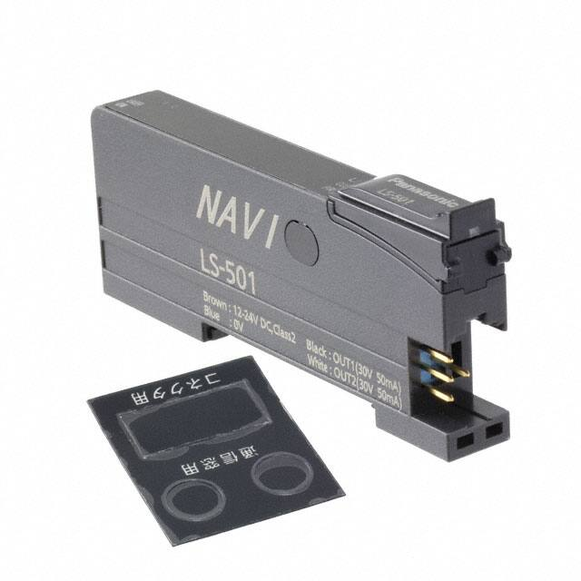


 工商网监
湘ICP备2023018690号
工商网监
湘ICP备2023018690号

