1111
FIBER
SENSORS
Ultra-compact Laser Collimated Beam Sensor
HL-T1 SERIES
Related Information
■■General terms and conditions.............. F-3
■■Glossary of terms / General precautions...... P.1587 / P.1595
■■Selection guide............................. P.1021~
■■About laser beam.......................... P.1593~
LASER
SENSORS
PHOTOELECTRIC
SENSORS
Conforming to
FDA regulations
(HL-T□F only)
MICRO
PHOTOELECTRIC
SENSORS
AREA
SENSORS
SAFETY LIGHT
CURTAINS /
SAFETY COMPONENTS
PRESSURE /
FLOW
SENSORS
INDUCTIVE
PROXIMITY
SENSORS
PARTICULAR
USE SENSORS
SENSOR
OPTIONS
SIMPLE
WIRE-SAVING
UNITS
WIRE-SAVING
SYSTEMS
MEASUREMENT
SENSORS
STATIC
CONTROL
DEVICES
LASER
MARKERS
PLC
HUMAN MACHINE
INTERFACES
ENERGY
MANAGEMENT
SOLUTIONS
FA COMPONENTS
MACHINE VISION
SYSTEMS
UV CURING
SYSTEMS
panasonic.net/id/pidsx/global
Ultra-compact sensor head A high-functionality
intelligent controller
Ultra-compact sensor head
Resolution of 4 µm 0.157 mil
The ultra-compact size and yet the high level of performance.
These sensors save space.
A high resolution of 4 μm 0.157 mil (at an average
64 cycles) allows high-precision positioning and size
judgment.
HL-T1001A(F)
HL-T1005A(F)
HL-T1010A(F)
Emitter
15mm 0.591 in
20 mm 0.787 in
15 mm
0.591 in
42 mm
1.654 in
20 mm
0.7487 in
19 mm 0.748 in
20 mm
0.787 in
15 mm 0.591 in
Other Products
HL-T1
LD
LA
Distinguishing size of
electronic components
Emitter
34 mm
1.339 in
15 mm 0.591 in
Selection
Guide
Laser
Displacement
Magnetic
Displacement
Contact
Displacement
Collimated
Beam Sensors
Metal-sheet
Double-feed Detection
Digital Panel
Controller
This product is classified as a
Class 1 Laser Product in IEC /
JIS standards and a Class II
Laser Product in FDA regulations.
Do not look at the laser beam
through optical system such as
a lens.
Receiver
25 mm
0.984 in
20 mm
0.787 in
Receiver
BASIC PERFORMANCE
Long sensing range
Long sensing range of 500 mm 19.685 in
[HL-T1005A(F), HL-T1010A(F)] and 2 m 6.562 ft
[HL-T1001A(F)] are available.
High-precision judgment even from
minute differences in light intensity
The sensors are sensitive Distinguishing opacity of glass
to minute differences in
light intensity, so that
they can judge even
the opacity of glass.
In addition, the amount
of light received can be
displayed as a percentage
to allow you to determine
permeation rates.
Minimum sensing object
diameter ø8 µm ø0.315 mil
HL-T1001A(F)
The laser with a beam
diameter of ø1 mm
ø0.039 in can sense
extremely small objects
with dimensions in
micrometers such as
bonding wires.
Adoption of a Class 1 laser
The adoption of a Class 1 laser (IEC / JIS) eliminates the
need for safety countermeasures, so that these sensors
can be used in photoelectric sensor applications with
confidence.
�Ultra-compact Laser Collimated Beam Sensor
HL-T1 SERIES
APPLICATIONS
Checking the positioning of chip components
1112
FIBER
SENSORS
Detecting defective lead frame seating
Sensing wafer position in wafer cassette
LASER
SENSORS
PHOTOELECTRIC
SENSORS
MICRO
PHOTOELECTRIC
SENSORS
AREA
SENSORS
SAFETY LIGHT
CURTAINS /
SAFETY COMPONENTS
PRESSURE /
FLOW
SENSORS
INDUCTIVE
PROXIMITY
SENSORS
PARTICULAR
USE SENSORS
FUNCTIONS
Fully equipped with convenient functionality
Analog output is switchable between current / voltage
A wide range of convenient features has been incorporated
into the unit’s compact body: standard received light setting
/ auto scaling setting / measurement processing (various
timer and hold functions) / differentiation / monitor focus
function. These features make the unit useful for a wide
variety of applications.
The analog output can be switched between either of
two different outputs; current (4 to 20 mA) / voltage
(±4 V). With the monitor focus function, the output can
be adjusted over the range from –5 V to +5 V, or from
0 V to +5 V, facilitating connectivity with a variety of
output devices.
Positioning
teaching
The actual value measured at the time when teaching
is performed is utilized as the threshold value.
Best suited for high-precision positioning.
2-point
teaching
In this teaching method, an intermediate level between
the first and the second teaching levels is utilized as
the threshold value. Minute differences, such as
changes as small as the thickness of a sheet of paper
between the sensing objects, can be detected when
this teaching method is utilized.
Automatic
teaching
With this teaching method, a series of periodic arbitrarily
measurements are taken automatically and an
intermediate value, between the maximum and minimum
values obtained by this measurement, is utilized as the
threshold value. The threshold value is therefore set in
relation to the sensing object. Best suited for
applications in which teaching must be performed
without stopping the current flow of operations.
The linear output is fully adjustable over the following
range (current: 4 to 20 mA / voltage: ±4 V). The usage
of the monitor focus function together with selectable
current / voltage switching for the linear output allows for
compatibility with a variety of output devices.
(Examples)
STATIC
CONTROL
DEVICES
LASER
MARKERS
PLC
HUMAN MACHINE
INTERFACES
MACHINE VISION
SYSTEMS
–4
UV CURING
SYSTEMS
+5
+1
0
5.0
0.197
Sensor display value (mm in)
In the event that
5 mm 0.197 in: +1 V
0 mm 0 in: +5 V
+5
+1
0
5.0
0.197
Sensor display value (mm in)
The linear output must be set by determining output
values (maximum; current: 0 to 23.5 mA / voltage: ±5.5 V)
at two different points, for the arbitrary display value.
MAINTENANCE
Self-check for laser diode deterioration
The intelligent controller performs self-checking for laser
diode deterioration. If the controller detects significant
deterioration (end of diode life), an error will be displayed
on the main digital display panel. This function enables
users to prepare in advance for potential laser diode
malfunctions.
MEASUREMENT
SENSORS
FA COMPONENTS
In the event that
5 mm 0.197 in: +5 V
0 mm 0 in: +1 V
Linear output voltage (V)
indicator
WIRE-SAVING
SYSTEMS
0
5.0
0.197
Sensor display value (mm in)
Detection resolution can be easily confirmed
The current resolution can be easily confirmed by setting
the controller to indicate resolution display mode.
By displaying the resolution, the marginal increment can
be easily determined for the threshold value setting,
helping to accurately determine whether sensing can be
performed.
Resolution
SIMPLE
WIRE-SAVING
UNITS
ENERGY
MANAGEMENT
SOLUTIONS
+4
Linear output voltage (V)
3 types of teaching functions are available: positioning
teaching / 2-point teaching / automatic teaching, thus
enabling a variety of applications to be accommodated
for many different types of production sites.
Monitor focus function
Linear output voltage (V)
3 types of teaching functions are now available
SENSOR
OPTIONS
Error display
Selection
Guide
Laser
Displacement
Magnetic
Displacement
Contact
Displacement
Collimated
Beam Sensors
Metal-sheet
Double-feed Detection
Digital Panel
Controller
Other Products
HL-T1
LD
LA
�1113
FIBER
SENSORS
LASER
SENSORS
PHOTOELECTRIC
SENSORS
Ultra-compact Laser Collimated Beam Sensor
HL-T1 SERIES
OPERABILITY
OPTIONS
Superior operability has been achieved
Calculations for 2 sensors are possible
All settings can be easily performed by using the four-way
keys and viewing the digital displays.
The calculation unit (optional) just needs to be connected
between the two controllers to enable calculations (addition
and subtraction) to be carried out for two sensors. No digital
panel controller is needed either.
MICRO
PHOTOELECTRIC
SENSORS
Large dual digital display
After power up, the measured value (red) and the
threshold value (yellow) are displayed
(letter height 7 mm 0.276 in)
AREA
SENSORS
Sheet width measurement
Judgment output indicators
SAFETY LIGHT
CURTAINS /
SAFETY
COMPONENTS
HIGH (Orange) / PASS (Green) / LOW
(Yellow) 3-color display
PRESSURE /
FLOW
SENSORS
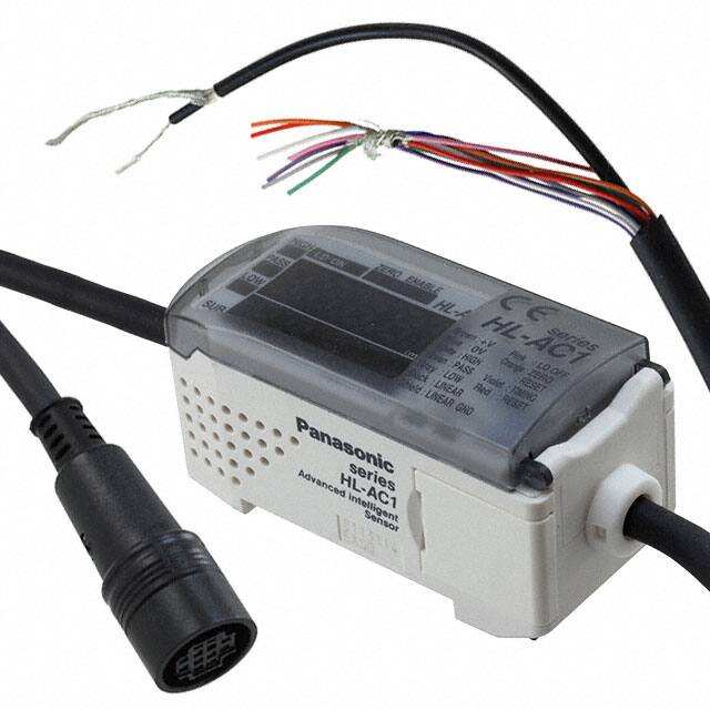
Calculation unit
HL-AC1-CL
INDUCTIVE
PROXIMITY
SENSORS
PARTICULAR
USE
SENSORS
SENSOR
OPTIONS
STATIC
CONTROL
DEVICES
LASER
MARKERS
PLC
HUMAN
MACHINE
INTERFACES
ENERGY
MANAGEMENT
SOLUTIONS
FA
COMPONENTS
MACHINE
VISION
SYSTEMS
UV
CURING
SYSTEMS
Selection
Guide
Laser
Displacement
Magnetic
Displacement
Contact
Displacement
Collimated
Beam
Sensors
Metal-sheet
Double-feed
Detection
Digital Panel
Controller
Other
Products
HL-T1
LD
LA
Sensor heads
Type
Appearance
Beam diameter ø1 mm
ø0.039 in type
MEASUREMENT
SENSORS
ORDER GUIDE
Sensing width 5 mm
0.197 in type
WIRE-SAVING
SYSTEMS
Easy operation with four-way keys
Sensing width 10 mm
0.394 in type
SIMPLE
WIRE-SAVING
UNITS
Sensing range
2 m 6.562 ft
500 mm 19.685 in
500 mm 19.685 in
Sensing width
Min. sensing
object
ø1 mm ø0.039 in
ø1 to ø2.5 mm
ø0.039 to ø0.098 in
at 500 to 2,000 mm
19.685 to 78.740 in
sensing range
ø8 µm ø0.315 mil
opaque object
ø50 µm ø1.969 mil
opaque object at
500 to 2,000 mm
19.685 to 78.740 in
sensing range
5 mm 0.197 in
10 mm 0.394 in
Conforming
standards / regulations
Model No.
IEC / JIS
HL-T1001A
FDA /
IEC / JIS
HL-T1001F
IEC / JIS
HL-T1005A
FDA /
IEC / JIS
HL-T1005F
IEC / JIS
HL-T1010A
FDA /
IEC / JIS
HL-T1010F
ø0.05 mm ø0.002 in
opaque object
ø0.1 mm ø0.004 in
opaque object
Note: The model No. with “P” shown on the label affixed to the product is the emitter, “D” shown on the label is the receiver.
Accessories
• MS-HLT1-1
Sensor mounting bracket
for HL-T1001A(F) /
HL-T1005A(F)
(Note)
Two M3 (length 20 mm 0.787 in)
screws with washers are attached.
Note: 2 sets are required to mount
the emitter/receiver.
• MS-LA3-1
Sensor mounting bracket
for HL-T1010A(F)
(Note)
Two M3 (length 25 mm 0.984 in)
screws with washers are attached.
• CN-HLT1-1
(Sensor head to controller connection cable)
�Ultra-compact Laser Collimated Beam Sensor
HL-T1 SERIES
1114
ORDER GUIDE
FIBER
SENSORS
LASER
SENSORS
Controllers
Type
Appearance
Model No.
PHOTOELECTRIC
SENSORS
Output
NPN output
MICRO
PHOTOELECTRIC
SENSORS
HL-AC1
AREA
SENSORS
NPN open-collector transistor
(Judgment output)
Current/voltage output
(Linear output)
SAFETY LIGHT
CURTAINS /
SAFETY
COMPONENTS
PNP output
PRESSURE /
FLOW
SENSORS
HL-AC1P
INDUCTIVE
PROXIMITY
SENSORS
PNP open-collector transistor
(Judgment output)
Current/voltage output
(Linear output)
PARTICULAR
USE
SENSORS
SENSOR
OPTIONS
SIMPLE
WIRE-SAVING
UNITS
Calculation unit
WIRE-SAVING
SYSTEMS
Appearance
Model No.
MEASUREMENT
SENSORS
STATIC
CONTROL
DEVICES
HL-AC1-CL
LASER
MARKERS
PLC
HUMAN
MACHINE
INTERFACES
OPTIONS
Designation
Side-view
attachment
ENERGY
MANAGEMENT
SOLUTIONS
Model No.
Description
HL-T1SV1
For HL-T1001A(F) /
T1005A(F) (1 pc.)
HL-T1SV2
For HL-T1010A(F)
(1 pc.)
Side-view attachment
• HL-T1SV1
• HL-T1SV2
MACHINE
VISION
SYSTEMS
The beam axis can be bent to a right
angle making universal mounting
possible.
UV
CURING
SYSTEMS
Controller
MS-HLAC1-1 Use when mounting the controller with screws.
mounting bracket
HL-T1CCJ4
Length: 4 m 13.123 ft
Net weight: 162 g approx.
HL-T1CCJ8
Length: 8 m 26.247 ft
Net weight: 330 g approx.
Extension cable
Extension cable for use between the controller
and its cable linking it with the sensor head.
Cabtyre cable with connectors on both ends
Cable outer diameter: ø5.2 mm ø0.205 in
Connector outer diameter:
ø15.5 mm ø0.610 in max.
FA
COMPONENTS
Selection
Guide
Mounted on both sides
Mounted on one side only
Controller mounting bracket
• MS-HLAC1-1
Laser
Displacement
Magnetic
Displacement
Contact
Displacement
Collimated
Beam
Sensors
Metal-sheet
Double-feed
Detection
Digital Panel
Controller
Other
Products
HL-T1
LD
LA
Extension cable
• HL-T1CCJ4
• HL-T1CCJ8
�1115
Sensor heads
Type Beam diameter ø1 mm ø0.039 in type
SAFETY LIGHT
CURTAINS /
SAFETY
COMPONENTS
PRESSURE /
FLOW
SENSORS
INDUCTIVE
PROXIMITY
SENSORS
PARTICULAR
USE
SENSORS
SENSOR
OPTIONS
SIMPLE
WIRE-SAVING
UNITS
WIRE-SAVING
SYSTEMS
MEASUREMENT
SENSORS
STATIC
CONTROL
DEVICES
Item
ENERGY
MANAGEMENT
SOLUTIONS
FA
COMPONENTS
FDA conformed type
HL-T1001F
Other
Products
HL-T1
LD
LA
500 mm 19.685 in
10 mm 0.394 in
Min. sensing object
ø50 µm ø1.969 mil
opaque object
ø0.05 mm ø0.002 in opaque object
ø0.1 mm ø0.004 in opaque object
Repeatability
(During the state in which light is half blocked)
4 µm 0.157 mil
(Note 2)
–
4 µm 0.157 mil (Note 2)
Linear output resolution
(Note 3)
4 µm 0.157 mil
(Note 2, 4)
–
4 µm 0.157 mil (Note 2)
Emission indicator
Green LED (lights up during laser emission)
Interference prevention function
Two units of sensors can be mounted close together. (When the controller interference prevention function is used)
Pollution degree
Ambient temperature
3 (industrial environment)
0 to +50 °C +32 to +122 °F (No dew condensation allowed), Storage: –25 to +70 °C –13 to +158 °F
Ambient humidity
Ambient illuminance
Voltage withstandability
35 to 85 % RH, Storage: 35 to 85 % RH
Incandescent light: 10,000 ℓx or less at the light-receiving face
1,000 V AC for one min. between all supply terminals connected together and enclosure
Insulation resistance
100 MΩ, or more, with 250 V DC megger between all supply terminals connected together and enclosure
Vibration resistance
10 to 500 Hz frequency, 1.5 mm 0.059 in double amplitude in X, Y and Z directions for two hours each
Shock resistance
IEC / JIS conformed type
FDA conformed type
Material
300 m/s2 acceleration (30 G approx.) in X, Y and Z directions three times each
Red semiconductor laser Class 1 (IEC / JIS)
Red semiconductor laser Class 1 (IEC / JIS)
modulated, max. output: 0.2 mW, peak
emission wavelength: 650 nm 0.026 mil
modulated, max. output: 0.35 mW,
peak emission wavelength: 650 nm 0.026 mil
Red semiconductor laser Class II (FDA)
Red semiconductor laser Class II (FDA)
modulated, max. output: 0.2 mW, peak
emission wavelength: 650 nm 0.026 mil
(IEC / JIS: Class 1)
modulated, max. output: 0.35 mW,
peak emission wavelength: 650 nm 0.026 mil
(IEC / JIS: Class 1)
Enclosure: Polyetherimide, Case cover: Polycarbonate, Front cover: Glass
0.09mm2 3-core shielded cable with connector, 0.5 m 1.640 ft long
Cable extension
Extension up to total 10 m 32.808 ft is possible, with the optional cable.
Emitter: 15 g approx., Receiver: 15 g approx.
Emitter: 30 g approx., Receiver: 20 g approx.
MS-HLT1-1(Sensor head mounting bracket): �One set of two brackets for both
the emitter and the receiver
CN-HLT1-1(Sensor head to controller connection cable): 1 cable
Laser beam alignment sticker: 2 pcs.
Label set (FDA conformed type only): 1 set
MS-LA3-1 (Sensor head mounting bracket):
One set of two brackets for both the emitter and the receiver
CN-HLT1-1 (Sensor head to controller connection cable): 1 cable
Laser beam alignment sticker: 2 pcs.
Label set (FDA conformed type only): 1 set
Notes: 1) Where measurement conditions have not been specified precisely, the conditions used were an ambient temperature of +20 °C +68 °F.
2) In case of an average sampling rate of 64 times.
3) Value calculated with the linear output allowance factor (±3 σ) when connected to the controller included in the calculation of the detection width.
4) This value was obtained by converting the range of linear output fluctuation (±3 σ) into a sensing width, assuming that the smallest sensing object
blocks the beam at the approximate center of the beam diameter of ø1 mm ø0.039 in.
Calculation unit
Model No.
Item
CE marking directive compliance
HL-AC1-CL
EMC Directive, RoHS Directive
Connected controller
HL-AC1, HL-AC1P
Current consumption
12 mA or less (supplied from the controller)
Connecting method
Connection indicator
Environmental resistance
Digital Panel
Controller
HL-AC1, HL-AC1P
ø8 µm ø0.315 mil
opaque object
Accessories
Contact
Displacement
HL-T1010F
5 mm 0.197 in
Net weight
Collimated
Beam
Sensors
Metal-sheet
Double-feed
Detection
HL-T1005F
EMC Directive, RoHS Directive
ø1 to ø2.5 mm ø0.039 to ø0.098 in
UV
CURING
SYSTEMS
Magnetic
Displacement
HL-T1010A
ø1 mm ø0.039 in
Cable
Laser
Displacement
Sensing width 10 mm 0.394 in type
HL-T1005A
Sensing width
MACHINE
VISION
SYSTEMS
Selection
Guide
Sensing width 5 mm 0.197 in type
0 to 500 mm 0 to 19.685 in 500 to 2,000 mm 19.685 to 78.74 in
Sensing range
Emitting element
HUMAN
MACHINE
INTERFACES
HL-T1001A
Applicable controller
LASER
MARKERS
PLC
IEC / JIS conformed type
CE marking directive compliance
Environmental resistance
AREA
SENSORS
Model No.
PHOTOELECTRIC
SENSORS
MICRO
PHOTOELECTRIC
SENSORS
HL-T1 SERIES
SPECIFICATIONS
FIBER
SENSORS
LASER
SENSORS
Ultra-compact Laser Collimated Beam Sensor
Ambient temperature
Ambient humidity
Voltage withstandablity
Connector
Orange LED (lights up when connected to the controller)
0 to +50 °C +32 to +122 °F (No dew condensation allowed), Storage: –15 to +60 °C +5 to +140 °F
35 to 85 % RH, Storage: 35 to 85 % RH
1,000 V AC for one min. between all supply terminals connected together and enclosure
Insulation resistance
100 MΩ, or more, with 500 V DC megger between all supply terminals connected together and enclosure
Vibration resistance
10 to 150 Hz frequency, 0.7 mm 0.028 in double amplitude in X, Y and Z directions for 80 min.
Shock resistance
300 m/s2 acceleration (30 G approx.) in X, Y and Z directions three times each
Material
Enclosure: ABS, Indicator part: Acrylic
Weight
Net weight: 50 g approx.
Note: Where measurement conditions have not been specified precisely, the conditions used were an ambient temperature of +20 °C +68 °F.
�Ultra-compact Laser Collimated Beam Sensor
HL-T1 SERIES
1116
SPECIFICATIONS
FIBER
SENSORS
LASER
SENSORS
Controllers
Type
Item
NPN output
HL-AC1
Model No.
CE marking directive compliance
HL-AC1P
HL-T1001A/T1001F, HL-T1005A/T1005F, HL-T1010A/T1010F
150 μs
Temperature characteristics
PRESSURE /
FLOW
SENSORS
±0.2 % F.S./°C (Note 3)
INDUCTIVE
PROXIMITY
SENSORS
1 / 2 / 4 / 8 / 16 / 32 / 64 / 128 / 256 / 512 / 1,024 / 2,048 / 4,096
NPN open-collector transistor
• Maximum sink current: 50 mA
• Applied voltage: 30 V DC or less (between judgment output and 0 V)
• Residual voltage: 1.2 V or less (at 50 mA sink current)
PNP open-collector transistor
• Maximum source current: 50 mA
• Applied voltage: 30 V DC or less (between judgment output and +V)
• Residual voltage: 2 V or less (at 50 mA source current)
SENSOR
OPTIONS
DC-12 or DC-13
Number of outputs
HIGH / PASS / LOW 3 values output
SIMPLE
WIRE-SAVING
UNITS
HIGH: ON when measured value > HIGH threshold value
PASS: ON when HIGH threshold value ≥ measured value ≥ LOW threshold value
LOW: ON when LOW threshold value > measured value
WIRE-SAVING
SYSTEMS
Short-circuit protection
Incorporated
Laser OFF input
0 V connection: Laser emission halt
Open: Laser emission
• Applied voltage: 30 V DC or less (leak current: 0.1 mA or less)
+V connection: Laser emission halt
Open: Laser emission
• Applied voltage: 30 V DC or less (leak current: 0.1 mA or less)
Zero reset input
0 V connection: Zero reset operates
Open: Zero reset ineffective
• Applied voltage: 30 V DC or less (leak current: 0.1 mA or less)
+V connection: Zero reset operates
Open: Zero reset ineffective
• Applied voltage: 30 V DC or less (leak current: 0.1 mA or less)
Timing input
0 V connection: Effective
Open: Ineffective
• Applied voltage: 30 V DC or less (leak current: 0.1 mA or less)
+V connection: Effective
Open: Ineffective
• Applied voltage: 30 V DC or less (leak current: 0.1 mA or less)
Reset input
0 V connection: Effective
Open: Ineffective
• Applied voltage: 30 V DC or less (leak current: 0.1 mA or less)
+V connection: Effective
Open: Ineffective
• Applied voltage: 30 V DC or less (leak current: 0.1 mA or less)
Laser emitting (LD ON)
Indicators
PARTICULAR
USE
SENSORS
Utilization category
Output operation
Judgment outputs
Green LED (lights up during laser emission)
HIGH: Orange LED (lights up when measured value > HIGH threshold value)
PASS: Green LED (lights up when HIGH threshold value ≥ measured value ≥ LOW threshold value)
LOW: Yellow LED (lights up when LOW threshold value > measured value)
Enable (ENABLE)
Green LED (lights up during normal operation)
Zero reset (ZERO)
Green LED (lights up when the zero reset function is enabled)
Main digital display
Sub-digital display
Main functions
Environmental resistance
AREA
SENSORS
SAFETY LIGHT
CURTAINS /
SAFETY
COMPONENTS
Current / voltage output switchable (Note 2)
• During current output: 4 to 20 mA/F.S., Maximum load resistance: 300 Ω
• During voltage output: ±4 V/F.S., Output impedance 100 Ω
(In the monitor focus function, it can also be set at ±5 V, 0 to 5 V, etc.)
Settable average sampling rate (Note 4)
Judgment outputs
(HIGH, PASS, LOW)
MICRO
PHOTOELECTRIC
SENSORS
12 to 24 V DC ±10 % Ripple P-P 10 % or less / 190 mA or less (when connected to the sensor head)
Measuring cycle
Linear output
PHOTOELECTRIC
SENSORS
EMC Directive, RoHS Directive
Applicable sensor head
Supply voltage / Current consumption
PNP output
Pollution degree
Ambient temperature
Ambient humidity
Voltage withstandability
5 digit red LED display
5 digit yellow LED display
• Measured value
display
• Setting value, light
amount value
resolution display
• Standard received light
setting
• Automatic scaling
• Scaling
RUN mode: Either the resolution or laser beam reception amount will be displayed.
THR mode: The threshold value will be displayed., Reverse mode: The display orientation will be reversed.
• Display reverse
• ECO display
• Display digits limitation
• Sample hold
• Peak hold
• Bottom hold
• Peak to peak hold
• Self peak hold
• Self bottom hold
• Zero reset
• Initial reset
• ON-delay timer
• OFF-delay timer
• One-shot timer
• Differentiation
• Sensitivity selection
• Threshold value direct
setting
• Positioning teaching
• 2-point teaching
• Automatic teaching
• Hysteresis width variability
• Monitor focus
• Non-measuring time
setting
• (A – B) calculation
(Note 5)
• (A + B) calculation
(Note 5)
• Mutual interference
prevention (Note 5)
• Laser deterioration
detection
• Key lock
• Zero reset memory
3 (industrial environment)
0 to +50 °C +32 to +122 °F (No dew condensation allowed), Storage: –25 to +65 °C –13 to +149 °F
10 to 150 Hz frequency, 0.7 mm 0.028 in double amplitude in X, Y and Z directions for 80 min.
I/O cable extension
Weight
PLC
HUMAN
MACHINE
INTERFACES
ENERGY
MANAGEMENT
SOLUTIONS
FA
COMPONENTS
MACHINE
VISION
SYSTEMS
Selection
Guide
Laser
Displacement
Magnetic
Displacement
Contact
Displacement
Collimated
Beam
Sensors
Metal-sheet
Double-feed
Detection
Digital Panel
Controller
Other
Products
35 to 85 % RH, Storage: 35 to 85 % RH
1,000 V AC for one min. between all supply terminals connected together and enclosure
Vibration resistance
I/O cable
LASER
MARKERS
RUN mode: Either the measured value (mm) or the hold value will be displayed.
Reverse mode: The display orientation will be reversed.
20 MΩ, or more, with 500 V DC megger between all supply terminals connected together and enclosure
Material
STATIC
CONTROL
DEVICES
UV
CURING
SYSTEMS
Insulation resistance
Shock resistance
MEASUREMENT
SENSORS
300 m/s2 acceleration (30 G approx.) in X, Y and Z directions three times each
Enclosure: Polybutylene terephthalate, Transparent cover: Polycarbonate
0.09 mm2 10-core composite cable, 2 m 6.562 ft long
Extension up to total 10 m 32.808 ft is possible, with 0.09 mm2 or more, cable. (Note 6)
Net weight: 140 g approx.
Notes: 1) Where measurement conditions have not been specified precisely, the conditions used were an ambient temperature of +20 °C +68 °F.
2) Switching between current and voltage is accomplished by a switch on the bottom of the controller.
3) This is a typical value when the sensor head is connected.
4) The judgment output and linear output and linear output response time is calculated by (Measuring cycle) × (Set average sampling rate + 1).
5) The calculation unit is necessary.
6) If the extension cable is longer than 10 m 32.808 ft, then it will not qualify for CE marking.
HL-T1
LD
LA
�1117
HL-AC1
D
50 mA max.
(Gray) LOW judgment output
ZD2
Tr3
Main circuit
ZD3 (Blue) GND (0 V)
SENSOR
OPTIONS
100Ω
WIRE-SAVING
SYSTEMS
UV
CURING
SYSTEMS
*1
(Orange / Violet) Zero reset input
*1
*1
(Red) Reset input
*1
(Orange / Violet) Zero reset input
(Red) Reset input
Current output
4 to 20 mA
(Black) Linear output
Current output:
Load 300 Ω or less
Voltage output:
10 kΩ or more
100Ω
Symbols … D: Reverse supply polarity protection diode
ZD1, ZD2, ZD3: Surge absorption zener diode
Tr1, Tr2, Tr3: PNP output transistor
Non-voltage contact or PNP open-collector transistor
or
or
• LD-OFF input, Timing input, Zero reset input, Reset input
Low (0 to 1.5 V): Effective
High (+V or open): Ineffective
• LD-OFF input, Timing input, Zero reset input, Reset input
Low (0 V or open): Ineffective
High [ +V to ( +V –1.5 V)]: Effective
SENSING CHARACTERISTICS (TYPICAL)
HL-T1005A HL-T1005F
HL-T1001A HL-T1001F
Correlation between transverse
deviation and output voltage
Correlation between transverse
deviation and output voltage
HL-T1
LD
4
Vertical direction
Horizontal direction
2
The graph depicts the correlation between
transverse deviation and output voltage when
the full-scale setting ranges from 0 V (light
beam is interrupted) to 5 V (light beam is fully
incident), using the Monitor Focus function.
0
4
2
0
2
4
0.157
0.079
0.079
0.157
(Up) Left
Center
Right (Down)
Deviation ℓ (mm in)
Digital Panel
Controller
Other
Products
6
Correlation between interrupted
beam width and output voltage
8
Linear output voltage (V)
LA
6
8
Horizontal direction
Vertical direction
500 mm 19.685 in
500 mm 19.685 in
Receiver
Receiver
Emitter
Emitter
ℓ
ℓ
Vertical direction
4
2
Horizontal direction
The graph depicts the correlation
between transverse deviation
and output voltage when the
full-scale setting ranges from 0 V
(light beam is interrupted) to 5 V
(light beam is fully incident),
using the Monitor Focus function.
0
10
5
0
5
10
0.394
0.197
0.197
0.394
(Up) Left
Center
Right (Down)
Deviation ℓ (mm in)
6
8
Horizontal direction
Vertical direction
500 mm 19.685 in
500 mm 19.685 in
Receiver
Receiver
Emitter
Emitter
ℓ
ℓ
4 Vertical direction
Horizontal direction
2
The graph depicts the
correlation between
transverse deviation and
output voltage when the
full-scale setting ranges
from 0 V (light beam is
interrupted) to 5 V (light
beam is fully incident),
using the Monitor Focus
function.
0
10
5
0
5
10
0.394
0.197
0.197
0.394
(Up) Left
Center
Right (Down)
Deviation ℓ (mm in)
HL-T1010A HL-T1010F
Correlation between transverse
deviation and output voltage
Correlation between interrupted
beam width and output voltage
8
Horizontal direction
Vertical direction
2 m 6.562 ft
2 m 6.562 ft
Receiver
Receiver
Emitter
Emitter
ℓ
ℓ
Linear output voltage (V)
Contact
Displacement
Collimated
Beam
Sensors
Metal-sheet
Double-feed
Detection
Users’ circuit
* 1
250 mm 9.843 in Sensing object
+ Receiver
ℓ
Emitter
Linear output voltage (V)
Magnetic
Displacement
Current output:
300 Ω or less
Voltage
Load
Voltage output:
(Shield)
Linear
GND
output ±4 V
10 kΩ or more
Internal circuit
Users’ circuit
Non-voltage contact or NPN open-collector transistor
Linear output voltage (V)
Laser
Displacement
12 to 24 V DC
±10 %
(Gray) LOW judgment output
Load
(Blue) GND (0 V)
ZD3
*1
(Violet) Timing input
8
Selection
Guide
–
*1
*1
* 1
FA
COMPONENTS
MACHINE
VISION
SYSTEMS
(Green) PASS judgment output
Load
50 mA max.
ZD2
6
–
500 mm 19.685 in
4
2
0
–10
–5
0
5
–0.394 –0.197
0.197
Screeing edge position ℓ (mm in)
10
0.394
250 mm 9.843 in Sensing object
ℓ
Receiver
+
Emitter
Linear output voltage (V)
ENERGY
MANAGEMENT
SOLUTIONS
Tr3
Symbols … D: Reverse supply polarity protection diode
ZD1, ZD2, ZD3: Surge absorption zener diode
Tr1, Tr2, Tr3: NPN output transistor
PLC
HUMAN
MACHINE
INTERFACES
ZD1
(Violet) Timing input
*1
Voltage
output ±4 V (Shield) Linear GND
50 mA max.
(White) HIGH judgment output
Load
50 mA max.
+
(Pink) LD-OFF input
(Pink) LD-OFF input
Internal circuit
12 to 24 V DC
±10 %
50 mA max.
Current output
4 to 20 mA
(Black) Linear output
SIMPLE
WIRE-SAVING
UNITS
–
Tr2
Main circuit
ZD1
Tr2
Tr1 D
Load
50 mA max.
Load
+
(Green) PASS judgment output
PARTICULAR
USE
SENSORS
LASER
MARKERS
(Brown) +V
(White) HIGH
Load
judgment output
Tr1
SAFETY LIGHT
CURTAINS /
SAFETY
COMPONENTS
STATIC
CONTROL
DEVICES
Color code
Color code
AREA
SENSORS
MEASUREMENT
SENSORS
PNP output type
(Brown) +V
MICRO
PHOTOELECTRIC
SENSORS
INDUCTIVE
PROXIMITY
SENSORS
HL-AC1P
NPN output type
PHOTOELECTRIC
SENSORS
PRESSURE /
FLOW
SENSORS
HL-T1 SERIES
I/O CIRCUIT DIAGRAMS
FIBER
SENSORS
LASER
SENSORS
Ultra-compact Laser Collimated Beam Sensor
6
–
500 mm
19.685 in
4
2
0
–10
–5
0
5
–0.394 –0.197
0.197
Screeing edge position ℓ (mm in)
10
0.394
�Ultra-compact Laser Collimated Beam Sensor
PRECAUTIONS FOR PROPER USE
• Never use this product as a sensing device
for personnel protection.
• In case of using sensing devices for
personnel protection, use products which
meet laws and standards, such as OSHA,
ANSI or IEC etc., for personnel protection
applicable in each region or country.
Function
Zero reset
function
• This product is classified as a Class 1 Laser
Product in IEC / JIS regulations and a Class
II Laser Product in FDA regulations. Do not
look at the laser beam through optical
system such as a lens.
• The following label is attached to the
product. Handle the product according to the
instruction given on the warning label.
The English warning label based
on FDA regulations is pasted on
the FDA conformed type.
Safety standards for laser beam products
• A laser beam can harm human being’s eyes, skin, etc.,
because of its high energy density. IEC has classified
laser products according to the degree of hazard and the
stipulated safety requirements.
The HL-T1 series is classified as Class 1 laser.
Classification by IEC 60825-1
Description
Lasers that are safe under reasonably foreseeable conditions of operation,
including the use of optical instruments for intrabeam viewing.
Safe use of laser products
• For the purpose of preventing users from suffering
injuries by laser products, IEC 60825-1 “Safety of laser
products”. Kindly check the standards before use.
(Refer to p.1593~ for information about laser beam.)
Standard
received light
setting
Scaling function
Details
The following tasks can be done by executing zero
reset.
• The display value can be set at “0”.
• The linear output when the display reads “0” is
made the center output value of the 2 points set
by monitor focus. (In the default state, the current
output is 12 mA and the voltage output is 0 V.)
The auto scaling function selects whether to display
the laser beam reception amount in the main-digital
display in “mm” units or in “%” units, and determines
whether the amount of laser beam received or the
amount of laser beam interrupted is displayed. With
the set standard laser beam reception amount as the
reference value, the current laser beam reception
amount (laser beam interrupted amount) is scaled
automatically and is displayed as well as being
output.
This function registers and stores the current laser
beam reception amount in memory as the standard
laser beam reception amount. The laser beam
reception amount during full laser beam entry
becomes the 100 % laser beam reception amount’s
full scale (F.S.). If this function is used, the display
and the linear output are set on the full scale (F.S.)
automatically. It can also be used to correct the laser
beam reception amount when there is a change in
the laser beam reception amount due to dirt, etc. on
the front glass.
The scaling function is a function that changes the
display value to the desired amount with respect to
the setting value. At the desired distance, the display
value can be input and changed.
Hysteresis width
setting function
This function sets the hysteresis to the desired value.
Monitor focus
function
With this function, the linear output range and
inclination, etc. with respect to the display value can
be specified. Setting is done by determining the 2
output values with respect to the desired display
values.
Differential
function
This function makes the amount of change in the
measured value an output value. Use this function
when measuring if you are paying attention to
changes in measured values, as when counting the
number of workpieces, etc.
Display reverse
function
The digital display’s direction can be selected. The
forward direction or the reverse direction to match
the direction of installation on the equipment can be
selected.
ECO display
function
This function makes the display dark and saves
electric power.
Display digits
limitation function
This determines the number of display digits in the
main-digital and sub-digital displays. If the number of
digits is limited, the digits are turned off beginning
with the lowest order digit.
Zero reset memory
function
This selects whether or not to save the zero reset
level in memory when the power is turned OFF. If
you desire to reproduce the zero reset level from the
previous operating session when you turn the power
ON again, then enable this function. If this function is
enabled, the zero reset level data are written into the
EEPROM each time.
Key lock
function
FIBER
SENSORS
LASER
SENSORS
Functions
Auto scaling
function
Class 1
1118
Refer to p.1595 for general precautions and p.1593~ for information about laser beam.
• This catalog is a guide to select a suitable product. Be
sure to read instruction manual attached to the product
prior to its use.
Classification
HL-T1 SERIES
The controller’s key input can be disabled. Once the
key input is disabled, the controller will not accept
any key inputs until the key lock is released. Use this
function to avoid changing the setting by mistake.
Connection
• This product is made to satisfy the specifications when the
sensor head is combined with the controller. In any other
combination, not only may it not satisfy the specifications,
but could be the cause of breakdown. So by all means,
use it so that there is a combination of the sensor head
and the controller.
PHOTOELECTRIC
SENSORS
MICRO
PHOTOELECTRIC
SENSORS
AREA
SENSORS
SAFETY LIGHT
CURTAINS /
SAFETY
COMPONENTS
PRESSURE /
FLOW
SENSORS
INDUCTIVE
PROXIMITY
SENSORS
PARTICULAR
USE
SENSORS
SENSOR
OPTIONS
SIMPLE
WIRE-SAVING
UNITS
WIRE-SAVING
SYSTEMS
MEASUREMENT
SENSORS
STATIC
CONTROL
DEVICES
LASER
MARKERS
PLC
HUMAN
MACHINE
INTERFACES
ENERGY
MANAGEMENT
SOLUTIONS
FA
COMPONENTS
MACHINE
VISION
SYSTEMS
UV
CURING
SYSTEMS
Selection
Guide
Laser
Displacement
Magnetic
Displacement
Contact
Displacement
Collimated
Beam
Sensors
Metal-sheet
Double-feed
Detection
Digital Panel
Controller
Other
Products
HL-T1
LD
LA
�1119
FIBER
SENSORS
LASER
SENSORS
Ultra-compact Laser Collimated Beam Sensor
HL-T1 SERIES
PRECAUTIONS FOR PROPER USE
Functional description
②
PHOTOELECTRIC
SENSORS
①
Refer to p.1595 for general precautions and p.1593~ for information about laser beam.
⑥
⑤
③ ⑫
⑨ ⑪
MICRO
PHOTOELECTRIC
SENSORS
AREA
SENSORS
SAFETY LIGHT
CURTAINS /
SAFETY
COMPONENTS
PRESSURE /
FLOW
SENSORS
④
INDUCTIVE
PROXIMITY
SENSORS
Description
PARTICULAR
USE
SENSORS
Laser emitting indicator
(LD ON)
(Green LED)
SENSOR
OPTIONS
WIRE-SAVING
SYSTEMS
MEASUREMENT
SENSORS
STATIC
CONTROL
DEVICES
LASER
MARKERS
PLC
HUMAN
MACHINE
INTERFACES
FA
COMPONENTS
MACHINE
VISION
SYSTEMS
UV
CURING
SYSTEMS
⑬
Function
Lights up when the sensor head is emitting laser beam.
When in the RUN mode, it displays the measured value (mm/%).
During measurement hold, it displays the hold value (mm/%).
In Reverse mode, the top and bottom are displayed in reverse.
Sub-digital display
(5 digit yellow LED)
When in the RUN mode, it displays the threshold value, voltage / current value, light reception
amount or resolution. When in the THR mode, it displays the respective threshold values. In
reverse mode, the top and bottom are displayed in reverse.
Enable indicator
(ENABLE)
(Green LED)
Lights up when operation is normal. Goes off when operation is abnormal
(if the sensor head is not connected when the power is turned on).
Zero reset indicator
(ZERO)
(Green LED)
Lights up when the zero reset function is enabled.
Mode selection switch
The following 3 modes can be selected.
• RUN mode: Measuring mode
• THR mode: The threshold values are set in this mode.
• FUN mode: Each of the settings are set in this mode.
Threshold value select
switch
When in the THR / RUN mode, this switches the set threshold value (HIGH / LOW).
UP key
Selection
Guide
Laser
Displacement
Magnetic
Displacement
Contact
Displacement
Collimated
Beam
Sensors
Metal-sheet
Double-feed
Detection
Other
Products
• RUN mode: Timing input
• THR mode: Changes the threshold value (forward direction)
• FUN mode: Changes the function setting value (forward direction)
DOWN key
• RUN mode: �Press for 3 sec. or more: Standard light reception amount setting input
• THR mode: Changes the threshold value (reverse direction)
• FUN mode: Changes the function setting value (reverse direction)
RIGHT key
• RUN mode: �Changes the contents of the sub-digital display (forward direction)
• THR mode: Changes the threshold value digit (forward direction)
• FUN mode: Sets function selection (forward direction)
LEFT key
• RUN mode: �Changes the contents of the sub-digital display (reverse direction)
• THR mode: Changes the threshold value digit (reverse direction)
• FUN mode: Sets function selection (reverse direction)
ENT key
Digital Panel
Controller
LA
⑩
Main digital display
(5 digit red LED)
ENERGY
MANAGEMENT
SOLUTIONS
LD
⑦
Judgment output indicators HIGH: Orange LED (lights up when measured value HIGH threshold value)
(HIGH / PASS / LOW)
PASS: Green LED (�lights up when HIGH threshold value measured value LOW threshold value)
(Orange / Green / Yellow LED) LOW: Yellow LED (lights up when LOW threshold value measured value)
SIMPLE
WIRE-SAVING
UNITS
HL-T1
⑧
• RUN mode: �Pressing for 1 sec. or more, executes zero reset.�Pressing together with the RIGHT
key for 3 sec. or more, cancels zero reset.
• THR mode: �When threshold value is blinking, the threshold value is set. When the threshold
value lights up, teaching is executed.
• FUN mode: �When the set value is blinking, the value is set.
�When the setting is being initialized, pressing for a long time executes initialization.
Others
• This product outputs the judgment of the laser light analog
quantity. Since there is variation in the light intensity between
the center and the edges of the detection area, and the
emitter side and the receiver side, the “display value” does
not equal “the actual dimensions”, so caution is necessary.
Use the displayed dimensional value as a criterion.
• If the object being measured has a mirror surface or is
a transparent body, it may be impossible to measure it
accurately, so please exercise caution.
• Absolutely do not attempt to disassemble this product.
�Ultra-compact Laser Collimated Beam Sensor
DIMENSIONS (Unit: mm in)
HL-T1 SERIES
The CAD data can be downloaded from our website.
HL-T1001A(F) HL-T1005A(F)
ø2.6 ø0.102 cable,
0.5 m 1.640 ft long (Gray)
Sensor head
2-ø3.2 ø0.126
2.8
0.110
34
1.339 16
0.630
0.2 0.008
(1.5) (0.059)
2-ø3.2 ø0.126
ø2.6 ø0.102 cable, 0.5 m 1.640 ft long (Black)
Manufactured by
J.S.T. Mfg. Co., Ltd.
2.8
XARR-04VF*
0.110
19
0.748
5 0.197
15
9
0.354 0.591
Manufactured by
J.S.T. Mfg. Co., Ltd.
XARR-04VF*
1120
(36.5)
(1.437)
(6.9)
(0.272)
Certification / identification label (Note 1)
(50 µm 1.969 mil polyester film)
15
9
0.591 0.354
* The sensor heads that were produced before January 2006 use the connector shown below.
Please note that the new connector and previous connector are incompatible.
Manufactured by Molex
51029-0410
Light beam shielding plate (Note 1)
Sensor head
2-ø3.2 ø0.126
ø2.6 ø0.102 cable,
0.5 m 1.640 ft long (Gray)
14
20
0.551 0.787
Manufactured by
J.S.T. Mfg. Co., Ltd. (36.5)
XARR-04VF*
(1.437)
22
0.866
(1.5)
(0.059)
10
0.394
25
0.984
2-ø3.2 ø0.126
ø2.6 ø0.102 cable, 0.5 m 1.640 ft long (Black)
2.8
Manufactured by
0.110
J.S.T. Mfg. Co., Ltd.
XARR-04VF*
* The sensor heads that were produced before January 2006 use the connector shown below.
Please note that the new connector and previous connector are incompatible.
MEASUREMENT
SENSORS
STATIC
CONTROL
DEVICES
LASER
MARKERS
PLC
ENERGY
MANAGEMENT
SOLUTIONS
FA
COMPONENTS
(10)
(0.394)
Manufactured by Molex
51029-0410
Light beam shielding plate (Note)
MACHINE
VISION
SYSTEMS
UV
CURING
SYSTEMS
Beam axis
20
0.787
20
0.787
Emitter
Receiver
Selection
Guide
Note: IEC / JIS conforming products do not contain light beam shielding
plate, or certification/identification label.
HL-AC1 HL-AC1P
Controller
Laser
Displacement
HL-AC1-CL
Calculation unit (Optional)
Mounting drawing with a mounting bracket MS-HLAC1-1 (Optional)
Connector for calculation unit
connection (on each side)
(3.6)
(0.142)
PRESSURE /
FLOW
SENSORS
HUMAN
MACHINE
INTERFACES
14
20
0.787 0.551
Certification / identification label (Note)
(50 μm 1.969 mil polyester film)
Emission indicator
(Green)
SAFETY LIGHT
CURTAINS /
SAFETY
COMPONENTS
WIRE-SAVING
SYSTEMS
HL-T1010A HL-T1010F
0.2
0.008
(6.9)(0.272)
AREA
SENSORS
SIMPLE
WIRE-SAVING
UNITS
Receiver
Notes: 1) IEC / JIS conforming products do not contain light beam shielding plate,
or certification / identification label.
2) The receiver of HL-T1001A(F) does not incorporate a slit.
42
1.654
MICRO
PHOTOELECTRIC
SENSORS
SENSOR
OPTIONS
15
0.591
Emitter
2.8
0.110
PHOTOELECTRIC
SENSORS
PARTICULAR
USE
SENSORS
Beam axis (Note 2)
15
0.591
LASER
SENSORS
INDUCTIVE
PROXIMITY
SENSORS
(10)
(0.394)
Emission indicator (Green)
FIBER
SENSORS
32.2 1.268
30 1.181
64.3
2.531
Linking connector
24.9
0.980
Magnetic
Displacement
Contact
Displacement
Collimated
Beam
Sensors
Metal-sheet
Double-feed
Detection
Digital Panel
Controller
Other
Products
Connection indicator (Orange)
4.3
0.169
34.3
1.350
13.2
0.520
3.9
0.154
22.4
16
0.882 0.630
13
36.8
0.512
1.449
2-ø3.2 ø0.126
150 5.906 approx.
ø5.1 ø0.201 cable
3.4
0.134
15.8
0.622
ø5.2 ø0.205 cable,
2 m 6.562 ft long
Suitable for 35 mm 1.378 in
width DIN rail
5.4
0.213
3.4 0.134
32.2
1.268 16.1
0.634
Connector for
sensor head connection
22.4 16
0.882 0.630
5.4 0.213
12 0.472
8 0.315
HL-T1
15.1
0.594
57 2.244
54.9 2.161
LD
LA
30 26
1.181 1.024
5
3.4 0.197
0.134
36.7
1.445
Suitable for 35 mm 1.378 in
width DIN rail
�1121
FIBER
SENSORS
LASER
SENSORS
PHOTOELECTRIC
SENSORS
Ultra-compact Laser Collimated Beam Sensor
DIMENSIONS (Unit: mm in)
MS-HLT1-1
AREA
SENSORS
1.1
0.043
5
0.197
PARTICULAR
USE
SENSORS
SIMPLE
WIRE-SAVING
UNITS
STATIC
CONTROL
DEVICES
LASER
MARKERS
t 1.2
t 0.047
17
0.669
12.5
(34.6) 14.5 0.492 3.2
0.126
(1.362) 0.571
10
0.394
9
0.354
7
0.276
3.2
0.126
5
5
0.197
0.197
3.4
0.134
17
0.669
24.5
0.965
MS-LA3-1
1
Assembly dimensions
2
20
0.787
14
0.551
2-ø3.2 ø0.126
13 6 0.236
0.512
14
0.551
MACHINE
VISION
SYSTEMS
14
0.551
3
0.118
2-ø3.2 ø0.126
UV
CURING
SYSTEMS
6
0.236
2.6
0.102
3.4
0.134
3.4
0.134
2.6 0.102
Mounting drawing with HL-T1010A’s receiver
2-ø3.2 ø0.126
2-M3 × 0.5 0.020
t 1.6
t 0.063
10
0.394
2.6
0.102
Laser
Displacement
Material: Cold rolled carbon steel (SPCC) (Uni-chrome plated)
Magnetic
Displacement
Two M3 (length 25 mm 0.984 in) screws with washers are attached.
MS-HLAC1-1
23
0.906
33
1.229
Controller mounting bracket (Optional)
34.8
1.370
22
0.866
16
0.630
Other
Products
2.5
0.098
7.3
0.287
3
0.118
3.4
0.134
26.8
1.055
16
0.630
14
0.551
10
0.394
3.4 0.134
2.6 0.102
23
0.906
13
0.512
Contact
Displacement
Digital Panel
Controller
3 0.118
3.4
0.134
3
0.118
10
0.394
t 1.6
t 0.063
16
0.630
2.6
0.102
14
0.551
(45.1)
23
(1.776) 0.906
3.4
0.134
13
0.512
6 0.236
23
0.906
20
0.787
14
0.551
2.6 0.102
3.4 0.134
14
0.551
23
0.906
LA
13.1
0.516
t 1.2
t 0.047
Sensor head mounting bracket for HL-T1010A(F) [Accessory for HL-T1010A(F)]
FA
COMPONENTS
LD
3.4 0.134
1.6 0.063
9 0.354
5 0.197
Two M3 (length 20 mm 0.787 in) screws with washers are attached.
ENERGY
MANAGEMENT
SOLUTIONS
HL-T1
3.4 0.134
3 0.118
17
9.5 0.669
0.374
Material: Cold rolled carbon steel (SPCC) (Uni-chrome plated)
HUMAN
MACHINE
INTERFACES
Collimated
Beam
Sensors
Metal-sheet
Double-feed
Detection
1.6 0.063
9
0.354
2-ø3.2 ø0.126
1.1 0.043
5
0.197
ø3.2 ø0.126
PLC
Selection
Guide
Mounting drawing with HL-T1005A’s receiver
t 1.6
t 0.063
13.1
0.516
9
0.354
3.4 0.134
17
0.669
6
0.236
2-M3 × 0.5 0.020
5
0.197
5 0.197
5 0.197
INDUCTIVE
PROXIMITY
SENSORS
Assembly dimensions
15
0.591
9
0.354
9
0.354
3.4
0.134
PRESSURE /
FLOW
SENSORS
MEASUREMENT
SENSORS
2
7
5
0.276 0.197
3.2 0.126
SAFETY LIGHT
CURTAINS /
SAFETY
COMPONENTS
WIRE-SAVING
SYSTEMS
The CAD data can be downloaded from our website.
Sensor head mounting bracket for HL-T1001A(F) / HL-T1005A(F) [Accessory for HL-T1001A(F) / HL-T1005A(F)]
3.4
0.134
1.1
9
ø3.2 ø0.126 0.043
0.354
1
MICRO
PHOTOELECTRIC
SENSORS
SENSOR
OPTIONS
HL-T1 SERIES
CN-HLT1-1
20
0.787
t 1.6
t 0.063
Sensor head to controller connection cable (Accessory for sensor head)
+200
2-ø3.2 ø0.126
46
1.811
3
0.118
ø15
ø0.591
Manufactured by Hirose
Electric Co.,Ltd. RP17-13P-12PC
Black
ø2.6 ø0.102 × 2
Manufactured by J.S.T. Mfg. Co., Ltd. XAP-04V-1*
3
0.118
5.4
0.213
5.4
0.213
32.2 27.2
1.268 1.071
1,500 0
59.055 +7.874
0
Gray
5.3
0.209
* The sensor heads that were produced
before January 2006 use the connector
shown below.
Please note that the new connector and
previous connector are incompatible.
27.2
1.071
3.4
0.134
t 1.0
t 0.039
Manufactured by
Molex 51030-0430
�Ultra-compact Laser Collimated Beam Sensor
DIMENSIONS (Unit: mm in)
HL-T1 SERIES
1122
The CAD data can be downloaded from our website.
HL-T1SV1
Side-view attachment for HL-T1001A(F) / HL-T1005A(F) (Optional)
Assembly dimensions
Mounting drawing with HL-T1005A’s receiver
2.7
0.106
2-ø2.2 ø0.087
Beam axis
Beam axis
7.5
0.295
15
0.591
2.2
0.087
15
0.591
19
0.748
SENSOR
OPTIONS
SIMPLE
WIRE-SAVING
UNITS
HL-T1SV2
Side-view attachment for HL-T1010A(F) (Optional)
Assembly dimensions
Mounting drawing with HL-T1010A’s receiver
2.8
0.110
21
0.827
STATIC
CONTROL
DEVICES
HUMAN
MACHINE
INTERFACES
25
0.984
Beam axis
ENERGY
MANAGEMENT
SOLUTIONS
FA
COMPONENTS
20
0.787
11
0.433
21
0.827
MEASUREMENT
SENSORS
PLC
(46)
(1.811)
Beam axis
WIRE-SAVING
SYSTEMS
LASER
MARKERS
20
0.787
20
0.787
2.2
0.087
PRESSURE /
FLOW
SENSORS
PARTICULAR
USE
SENSORS
12.5
0.492
Two M2 (length 6 mm 0.236 in) screws with washers are attached.
20 15.6
0.787 0.614
MICRO
PHOTOELECTRIC
SENSORS
INDUCTIVE
PROXIMITY
SENSORS
Material: Polyetherimide (Enclosure), Glass (Front cover)
2-ø2.2 ø0.087
PHOTOELECTRIC
SENSORS
SAFETY LIGHT
CURTAINS /
SAFETY
COMPONENTS
(34)
(1.339)
15
0.591
15
10.6
0.591 0.417
LASER
SENSORS
AREA
SENSORS
15
0.591
15
0.591
FIBER
SENSORS
MACHINE
VISION
SYSTEMS
21
0.827
UV
CURING
SYSTEMS
Material: Polyetherimide (Enclosure), Glass (Front cover)
Two M2 (length 6 mm 0.236 in) screws with washers are attached.
Selection
Guide
Laser
Displacement
Magnetic
Displacement
Contact
Displacement
Collimated
Beam
Sensors
Metal-sheet
Double-feed
Detection
Digital Panel
Controller
Other
Products
HL-T1
LD
LA
�


 工商网监
湘ICP备2023018690号
工商网监
湘ICP备2023018690号
