5 mm Low profile,
2 Form C and 2 A (surfacemount type) relays
TQ RELAYS
FEATURES
1. Flat compact size
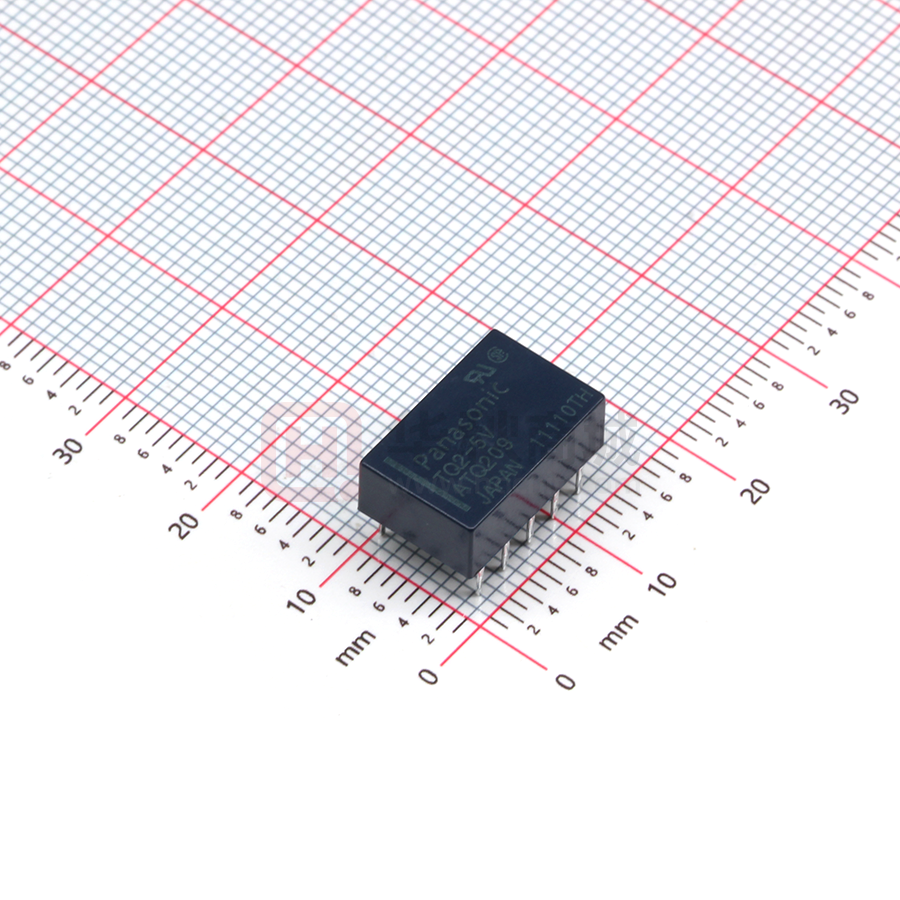
14.0 (L) × 9.0 (W) × 5.0 (H) mm
.551 (L) × .354 (W) × .197 (H) inch
2. Nominal operating power:
High sensitivity of 140mW (2 Form
C single side stable type)
3. Suitable for SMD automatic
insertion (SA type)
With a height of 5.6 mm .220 inch, the
relays meet JIS C 0806 specifications.
4. DIL terminal array enables use of IC
sockets
5. Low thermal electromotive force
(approx. 5 μV)
[approx. 2 μV (surface-mount type)]
6. Latching types also available
7. Self-clinching terminal also
available
RoHS compliant
8. A range of surface-mount types is
also available
SA: Low-profile surface-mount
terminal type
SL: High connection reliability surfacemount terminal type
SS: Space saving surface-mount
terminal type
9. M.B.B. contact types available
TYPICAL APPLICATIONS
1. Telephone-related equipment
2. Communications
3. Measurement equipment
4. OA equipment
5. Industrial machines
ORDERING INFORMATION
TQ 2
Contact arrangement
2: 2 Form C
Terminal shape
Nil: Standard PC board terminal
H: Self-clinching terminal
SA: SA type
SL: SL type
SS: SS type
Operating function
Nil: Single side stable
L: 1 coil latching
L2: 2 coil latching
MBB function
Nil: Standard (B.B.M.) type
2M: 2M.B.B. type
Nominal coil voltage (DC)*
1.5 (SMD only), 3, 4.5, 5, 6, 9, 12, 24, 48V
Packing style
Nil: Tube packing
X: Tape and reel (picked from 1/2/3/4/5-pin side)
Z: Tape and reel packing (picked from the 6/7/8/9/10-pin side)
Notes: 1. *48 V coil type: Single side stable only
2. In case of 5 V transistor drive circuit, it is recommended to use 4.5 V type relay.
–1–
ASCTB14E 201407-T
�TQ
TYPES
■ Standard PC board terminal and self-clinching terminal
1. Standard (B.B.M.) type
1) Standard PC board terminal
Contact
arrangement
Nominal coil
voltage
2 Form C
3 V DC
4.5 V DC
5 V DC
6 V DC
9 V DC
12 V DC
24 V DC
48 V DC
Single side stable
Part No.
TQ2-3V
TQ2-4.5V
TQ2-5V
TQ2-6V
TQ2-9V
TQ2-12V
TQ2-24V
TQ2-48V
1 coil latching
Part No.
TQ2-L-3V
TQ2-L-4.5V
TQ2-L-5V
TQ2-L-6V
TQ2-L-9V
TQ2-L-12V
TQ2-L-24V
—
2 coil latching
Part No.
TQ2-L2-3V
TQ2-L2-4.5V
TQ2-L2-5V
TQ2-L2-6V
TQ2-L2-9V
TQ2-L2-12V
TQ2-L2-24V
—
1 coil latching
Part No.
TQ2H-L-3V
TQ2H-L-4.5V
TQ2H-L-5V
TQ2H-L-6V
TQ2H-L-9V
TQ2H-L-12V
TQ2H-L-24V
—
2 coil latching
Part No.
TQ2H-L2-3V
TQ2H-L2-4.5V
TQ2H-L2-5V
TQ2H-L2-6V
TQ2H-L2-9V
TQ2H-L2-12V
TQ2H-L2-24V
—
Standard packing (2 Form C): Tube: 50 pcs.; Case: 1,000 pcs.
2) Self-clinching terminal
Contact
arrangement
Nominal coil
voltage
2 Form C
3 V DC
4.5 V DC
5 V DC
6 V DC
9 V DC
12 V DC
24 V DC
48 V DC
Single side stable
Part No.
TQ2H-3V
TQ2H-4.5V
TQ2H-5V
TQ2H-6V
TQ2H-9V
TQ2H-12V
TQ2H-24V
TQ2H-48V
Note: Types (“-3” to the end of part No.) designed to withstand strong vibration caused, for example, by the use of terminal cutters, can also be ordered.
However, please contact us if you need parts for use in low level load.
2. M.B.B. type
1) Standard PC board terminal
Contact arrangement
Nominal coil voltage
2 Form C
3 V DC
4.5 V DC
5 V DC
6 V DC
9 V DC
12 V DC
24 V DC
Single side stable
Part No.
TQ2-2M-3V
TQ2-2M-4.5V
TQ2-2M-5V
TQ2-2M-6V
TQ2-2M-9V
TQ2-2M-12V
TQ2-2M-24V
Standard packing: Tube: 50 pcs.; Case: 1,000 pcs.
2) Self-clinching terminal
Contact arrangement
Nominal coil voltage
2 Form C
3 V DC
4.5 V DC
5 V DC
6 V DC
9 V DC
12 V DC
24 V DC
Single side stable
Part No.
TQ2H-2M-3V
TQ2H-2M-4.5V
TQ2H-2M-5V
TQ2H-2M-6V
TQ2H-2M-9V
TQ2H-2M-12V
TQ2H-2M-24V
Standard packing: Tube: 50 pcs.; Case: 1,000 pcs.
Notes: 1. Latching types are available by request. Please consult us for details.
2. UL/CSA approved (UL file No.:E 43149, CSA file No.: LR26550)
3. Types (“-1” to the end of part No.) designed to withstand strong vibration caused, for example, by the use of terminal cutters, can also be ordered.
However, please contact us if you need parts for use in low level load and low thermal power.
–2–
ASCTB14E 201407-T
�TQ
■ Surface-mount terminal
1) Tube packing
Contact
arrangement
Nominal coil
voltage
2c
1.5 V DC
3 V DC
4.5 V DC
5 V DC
6 V DC
9 V DC
12 V DC
24 V DC
48 V DC
Single side stable
Part No.
TQ2S�-1.5V
TQ2S�-3V
TQ2S�-4.5V
TQ2S�-5V
TQ2S�-6V
TQ2S�-9V
TQ2S�-12V
TQ2S�-24V
TQ2S�-48V
1 coil latching
Part No.
TQ2S�-L-1.5V
TQ2S�-L-3V
TQ2S�-L-4.5V
TQ2S�-L-5V
TQ2S�-L-6V
TQ2S�-L-9V
TQ2S�-L-12V
TQ2S�-L-24V
—
2 coil latching
Part No.
TQ2S�-L2-1.5V
TQ2S�-L2-3V
TQ2S�-L2-4.5V
TQ2S�-L2-5V
TQ2S�-L2-6V
TQ2S�-L2-9V
TQ2S�-L2-12V
TQ2S�-L2-24V
—
�: For each surface-mounted terminal identification, input the following letter. SA type: A, SL type: L, SS type: S
Standard packing: Tube: 50 pcs.; Case: 1,000 pcs.
2) Tape and reel packing
Contact
arrangement
Nominal coil
voltage
2 Form C
1.5 V DC
3 V DC
4.5 V DC
5 V DC
6 V DC
9 V DC
12 V DC
24 V DC
48 V DC
Single side stable
Part No.
TQ2S�-1.5V-Z
TQ2S�-3V-Z
TQ2S�-4.5V-Z
TQ2S�-5V-Z
TQ2S�-6V-Z
TQ2S�-9V-Z
TQ2S�-12V-Z
TQ2S�-24V-Z
TQ2S�-48V-Z
1 coil latching
Part No.
TQ2S�-L-1.5V-Z
TQ2S�-L-3V-Z
TQ2S�-L-4.5V-Z
TQ2S�-L-5V-Z
TQ2S�-L-6V-Z
TQ2S�-L-9V-Z
TQ2S�-L-12V-Z
TQ2S�-L-24V-Z
—
2 coil latching
Part No.
TQ2S�-L2-1.5V-Z
TQ2S�-L2-3V-Z
TQ2S�-L2-4.5V-Z
TQ2S�-L2-5V-Z
TQ2S�-L2-6V-Z
TQ2S�-L2-9V-Z
TQ2S�-L2-12V-Z
TQ2S�-L2-24V-Z
—
�: For each surface-mounted terminal identification, input the following letter. SA type: A, SL type: L, SS type: S
Standard packing: Tape and reel: 500 pcs.; Case: 1,000 pcs.
Note: Tape and reel packing symbol “-Z” is not marked on the relay. “X” type tape and reel packing (picked from 1/2/3/4-pin side) is also available.
RATING
■ Standard PC board terminal and self-clinching terminal
1. Coil data
[Standard (B.B.M.) type]
1) Single side stable (2 Form C)
Nominal coil
voltage
3
Drop-out voltage
(at 20°C 68°F)
V DC
4.5 V DC
5 V DC
6 V DC
9 V DC
12 V DC
24 V DC
48
Pick-up voltage
(at 20°C 68°F)
Nominal operating
current
[±10%] (at 20°C 68°F)
46.7 mA
75%V or less of
nominal voltage*
(Initial)
10%V or more of
nominal voltage*
(Initial)
V DC
31.1
28.1
23.3
15.5
11.7
8.3
mA
mA
mA
mA
mA
mA
6.25 mA
Coil resistance
[±10%] (at 20°C 68°F)
Nominal operating
power
Max. applied voltage
(at 20°C 68°F)
140 mW
150%V of
nominal voltage
64.3 Ω
144.6 Ω
178 Ω
257 Ω
579 Ω
1,028 Ω
2,880 Ω
7,680
Ω
200 mW
300 mW
120%V of
nominal voltage
Nominal operating
power
Max. applied voltage
(at 20°C 68°F)
100 mW
150%V of
nominal voltage
2) 1 coil latching (2 Form C)
Nominal coil
voltage
3
Set voltage
(at 20°C 68°F)
Reset voltage
(at 20°C 68°F)
V DC
4.5 V DC
5 V DC
6 V DC
9 V DC
12 V DC
24 V DC
75%V or less of
nominal voltage*
(Initial)
75%V or less of
nominal voltage*
(Initial)
Nominal operating
current
[±10%] (at 20°C 68°F)
33.3 mA
22.2 mA
20 mA
16.7 mA
11.1 mA
8.3 mA
6.3 mA
–3–
Coil resistance
[±10%] (at 20°C 68°F)
90
Ω
202.5 Ω
250 Ω
360 Ω
810 Ω
1,440 Ω
3,840 Ω
150 mW
ASCTB14E 201407-T
�TQ
3) 2 coil latching (2 Form C)
Nominal coil
voltage
3
Set voltage
(at 20°C 68°F)
Reset voltage
(at 20°C 68°F)
Nominal operating
current
[±10%] (at 20°C 68°F)
Set coil
Reset coil
V DC
66.7 mA
66.7 mA
4.5 V DC
5 V DC
6 V DC
9 V DC
12 V DC
44.4 mA
40 mA
33.3 mA
22.2 mA
16.7 mA
44.4 mA
40 mA
33.3 mA
22.2 mA
16.7 mA
12.5 mA
12.5 mA
24
75%V or less of
nominal voltage*
(Initial)
75%V or less of
nominal voltage*
(Initial)
V DC
Coil resistance
[±10%] (at 20°C 68°F)
Set coil
45
101.2 Ω
125 Ω
180 Ω
405 Ω
720 Ω
1,920
Reset coil
Ω
Ω
45
Max. applied voltage
(at 20°C 68°F)
Set coil
Reset coil
200 mW
200 mW
150%V of
nominal voltage
300 mW
300 mW
120%V of
nominal voltage
Ω
101.2 Ω
125 Ω
180 Ω
405 Ω
720 Ω
1,920
Nominal operating
power
Ω
[M.B.B. type]
Nominal coil
voltage
3
Drop-out voltage
(at 20°C 68°F)
Pick-up voltage
(at 20°C 68°F)
V DC
4.5 V DC
5 V DC
6 V DC
9 V DC
12 V DC
24 V DC
80%V or less of
nominal voltage*
(Initial)
10%V or more of
nominal voltage*
(Initial)
Nominal operating
current
[±10%] (at 20°C 68°F)
66.7 mA
Coil resistance
[±10%] (at 20°C 68°F)
Nominal operating
power
Max. applied voltage
(at 20°C 68°F)
200 mW
150%V of
nominal voltage
45 Ω
101 Ω
125 Ω
180 Ω
405 Ω
720 Ω
2,880 Ω
44.4 mA
40 mA
33.3 mA
22.2 mA
16.7 mA
8.3 mA
*Pulse drive (JIS C 5442-1986)
2. Specifications
Characteristics
Contact
Rating
Item
Arrangement
Initial contact resistance, max.
Contact material
Nominal switching capacity
Max. switching power
Max. switching voltage
Max. switching current
Min. switching capacity (Reference value)*1
Specifications
2 Form C, 2 Form D (M.B.B.)
Max. 50mΩ (By voltage drop 6 V DC 1A)
Ag+Au clad
1 A 30 V DC, 0.5 A 125 V AC (resistive load)
30 W (DC), 62.5 V A (AC) (resistive load)
110 V DC, 125 V AC
1A
10μA 10mV DC
Single side stable
Nominal
operating power 1 coil latching
2 coil latching
Standard (B.B.M) type: 140 mW (3 to 12 V DC), 200 mW (24 V DC), 300 mW (48 V DC)
M.B.B. type: 200 mW
100 mW (3 to 12 V DC), 150 mW (24 V DC)
200 mW (3 to 12 V DC), 300 mW (24 V DC)
Insulation resistance (Initial)
Min. 1,000MΩ (at 500V DC)
Measurement at same location as “Initial breakdown voltage” section.
Between open contacts
Electrical
characteristics
Breakdown
voltage (Initial)
Between contact and coil
Between contact sets
Temperature rise (at 20°C 68°F)
Operate time [Set time] (at 20°C 68°F)
Release time [Reset time] (at 20°C 68°F)
Mechanical
characteristics
Expected life
Conditions
Shock
resistance
Functional
Destructive
Functional
Destructive
Mechanical (at 180 cpm)
Vibration
resistance
Electrical (at 20 cpm)
Conditions for operation, transport and
storage*2
Max. operating speed (at rated load)
Unit weight
Standard (B.B.M) type: 750 Vrms for 1min. (Detection current: 10 mA),
M.B.B. type: 300 Vrms for 1 min. (Detection current: 10 mA)
1,000 Vrms for 1min. (Detection current: 10 mA)
1,000 Vrms for 1min. (Detection current: 10 mA)
Max. 50°C (By resistive method, nominal coil voltage applied to the coil; contact carrying current: 1A.)
Max. 3 ms [Max. 3 ms] (Nominal coil voltage applied to the coil, excluding contact bounce time.)
Max. 3 ms [Max. 3 ms] (Nominal coil voltage applied to the coil, excluding contact bounce time.)
(without diode)
Min. 490 m/s2 (Half-wave pulse of sine wave: 11 ms; detection time: 10μs.)
Min. 980 m/s2 (Half-wave pulse of sine wave: 6 ms.)
10 to 55 Hz at double amplitude of 3 mm (Detection time: 10μs.)
10 to 55 Hz at double amplitude of 5 mm
Standard (B.B.M) type: Min. 108, M.B.B. type: Min. 107
Standard (B.B.M) type: Min. 2×10⁵ (1 A 30 V DC resistive), Min. 105 (0.5 A 125 V AC resistive)
M.B.B. type: Min. 105 (1 A 30 V DC resistive)
Standard (B.B.M) type:
Ambient temperature: –40°C to +70°C –40°F to +158°F;
Humidity: 5 to 85% R.H. (Not freezing and condensing at low temperature)
M.B.B. type:
Ambient temperature: –40°C to +50°C –40°F to +122°F;
Humidity: 5 to 85% R.H. (Not freezing and condensing at low temperature)
20 cpm
Approx. 1.5 g .053 oz
Notes: *1 This value can change due to the switching frequency, environmental conditions, and desired reliability level, therefore it is recommended to check this with the
actual load. TX/TX-S/TX-D relay AgPd contact type are available for low level load switching (10V DC, 10mA max. level).
*2 Refer to “AMBIENT ENVIRONMENT” in GENERAL APPLICATION GUIDELINES.
–4–
ASCTB14E 201407-T
�TQ
■ Surface-mount terminal
1. Coil data
1) Single side stable
Nominal operating
current
(at 20°C 68°F)
Coil resistance
[±10%] (at 20°C 68°F)
1.5 V DC
93.8 mA
16
3 V DC
4.5 V DC
5 V DC
6 V DC
9 V DC
12 V DC
24 V DC
46.7 mA
31 mA
28.1 mA
23.3 mA
15.5 mA
11.7 mA
8.3 mA
64.3 Ω
145 Ω
178 Ω
257 Ω
579 Ω
1,028 Ω
2,880 Ω
Nominal coil
voltage
48
Pick-up voltage
(at 20°C 68°F)
75%V or less of
nominal voltage*
(Initial)
Drop-out voltage
(at 20°C 68°F)
10%V or more of
nominal voltage*
(Initial)
V DC
6.3 mA
7,680
Nominal operating
power
Max. applied voltage
(at 20°C 68°F)
140 mW
150%V of
nominal voltage
Ω
Ω
200 mW
300 mW
120%V of
nominal voltage
Nominal operating
power
Max. applied voltage
(at 20°C 68°F)
70 mW
150%V of
nominal voltage
2) 1 coil latching
1.5 V DC
Nominal operating
current
(at 20°C 68°F)
46.9 mA
3 V DC
4.5 V DC
5 V DC
6 V DC
9 V DC
12 V DC
23.3 mA
15.6 mA
14 mA
11.7 mA
7.8 mA
5.8 mA
Nominal coil
voltage
24
Set voltage
(at 20°C 68°F)
75%V or less of
nominal voltage*
(Initial)
Reset voltage
(at 20°C 68°F)
75%V or less of
nominal voltage*
(Initial)
V DC
4.2 mA
Coil resistance
[±10%] (at 20°C 68°F)
32
Ω
128.6 Ω
289.3 Ω
357 Ω
514 Ω
1,157 Ω
2,057 Ω
5,760
Ω
100 mW
3) 2 coil latching
Nominal coil
voltage
1.5 V DC
3 V DC
4.5 V DC
5 V DC
6 V DC
9 V DC
12 V DC
24 V DC
Set voltage
(at 20°C 68°F)
75%V or less of
nominal voltage*
(Initial)
Reset voltage
(at 20°C 68°F)
75%V or less of
nominal voltage*
(Initial)
Nominal operating
current
(at 20°C 68°F)
Set coil
Reset coil
93.8 mA
93.8 mA
46.7 mA
31 mA
28.1 mA
23.3 mA
15.5 mA
11.7 mA
8.3 mA
46.7 mA
31 mA
28.1 mA
23.3 mA
15.5 mA
11.7 mA
8.3 mA
Coil resistance
[±10%] (at 20°C 68°F)
Set coil
16 Ω
Reset coil
16 Ω
64.3 Ω
145 Ω
178 Ω
257 Ω
579 Ω
1,028 Ω
2,880 Ω
64.3 Ω
145 Ω
178 Ω
257 Ω
579 Ω
1,028 Ω
2,880 Ω
Nominal operating
power
Set coil
Reset coil
140 mW
140 mW
200 mW
200 mW
Max. applied voltage
(at 20°C 68°F)
150%V of
nominal voltage
*Pulse drive (JIS C 5442-1986)
–5–
ASCTB14E 201407-T
�TQ
2. Specifications
Characteristics
Contact
Rating
Item
Arrangement
Initial contact resistance, max.
Contact material
Nominal switching capacity
Max. switching power
Max. switching voltage
Max. switching current
Min. switching capacity (Reference value)*1
Nominal operating
power
Single side stable
1 coil latching
2 coil latching
Insulation resistance (Initial)
Electrical
characteristics
1,000 Vrms for 1 min. (Detection current: 10 mA)
1,500 Vrms for 1 min. (Detection current: 10 mA)
1,500 Vrms for 1 min. (Detection current: 10 mA)
Surge breakdown
voltage (Initial)
Between open contacts
Between contacts and coil
1,500 V (10×160μs) (FCC Part 68)
2,500 V (2×10μs) (Bellcore)
Max. 50°C
(By resistive method, nominal coil voltage applied to the coil; contact carrying current: 2A.)
Max. 4 ms [Max. 4 ms] (Nominal coil voltage applied to the coil, excluding contact bounce
time.)
Max. 4 ms [Max. 4 ms] (Nominal coil voltage applied to the coil, excluding contact bounce
time.) (without diode)
Min. 750 m/s2 (Half-wave pulse of sine wave: 6 ms; detection time: 10μs.)
Min. 1,000 m/s2 (Half-wave pulse of sine wave: 6 ms.)
10 to 55 Hz at double amplitude of 3.3 mm (Detection time: 10μs.)
10 to 55 Hz at double amplitude of 5 mm
Min. 108 (at 180 cpm)
Min. 105 (2 A 30 V DC resistive), Min. 2×10⁵ (1 A 30 V DC resistive),
Min. 105 (0.5 A 125 V AC resistive) (at 20 cpm)
Ambient temperature:
–40°C to +85°C –40°F to +185°F, Max. –40°C to +70°C (2A) Max. –40°F to +158°F (2A);
Humidity: 5 to 85% R.H. (Not freezing and condensing at low temperature)
20 cpm
Approx. 2 g .071 oz
Release time [Reset time] (at 20°C 68°F)
Functional
Destructive
Functional
Vibration resistance
Destructive
Mechanical
Shock resistance
Conditions
Electrical
Conditions for operation, transport and storage*2
Max. operating speed (at rated load)
Unit weight
140 mW (1.5 to 12 V DC), 200 mW (24 V DC), 300 mW (48 V DC)
70 mW (1.5 to 12 V DC), 100 mW (24 V DC)
140 mW (1.5 to 12 V DC), 200 mW (24 V DC)
Min. 1,000MΩ (at 500V DC)
Measurement at same location as “Initial breakdown voltage” section.
Between open contacts
Between contact and coil
Between contact sets
Operate time [Set time] (at 20°C 68°F)
Expected life
10μA 10mV DC
Breakdown voltage
(Initial)
Temperature rise (at 20°C 68°F)
Mechanical
characteristics
Specifications
2 Form C
Max. 75 mΩ (By voltage drop 6 V DC 1A)
AgNi type+Au clad
2 A 30 V DC, 0.5 A 125 V AC (resistive load)
60 W (DC), 62.5 VA (AC) (resistive load)
220 V DC, 125 V AC
2A
Notes: *1 This value can change due to the switching frequency, environmental conditions, and desired reliability level, therefore it is recommended to check this with the
actual load. (TX/TX-S/TX-D relay AgPd contact type are available for low level load switching [10V DC, 10mA max. level])
*2 Refer to “AMBIENT ENVIRONMENT” in GENERAL APPLICATION GUIDELINES.
–6–
ASCTB14E 201407-T
�TQ
REFERENCE DATA
■ Standard PC board terminal and self-clinching terminal
1. Maximum switching capacity
2. Life curve
3. Mechanical life
1.0
0.5
0.4
0.3
Ratio against the rated voltage, %V
DC load (cosϕ=1)
AC load (cosϕ=1)
No. of operations, ×104
Switching current, A
Tested sample: TQ2-12V, 10 pcs.
30 V DC resistive load
100
125 V AC resistive load
10
0.2
30
0
100
200
Switching voltage,V
100
90
80
Pick-up voltage
Max.
Min.
70
60
50
40
Drop-out voltage
30
Max.
20
Min.
10
0
0.5
1.0
Switching current, A
10
100
1,000
10,000
No. of operations, ×104
4.-(1) Electrical life (DC load)
4.-(2) Electrical life (AC load)
Tested sample: TQ2-12V, 6 pcs.
Condition: 1 A 30 V DC resistive load, 20 cpm
Tested sample: TQ2-12V, 6 pcs.
Condition: 0.5 A 125 V AC resistive load, 20 cpm
Change of contact resistance
100
90
90
Pick-up voltage
Max.
70
Min.
60
50
40
Drop-out voltage
Max.
30
20
Min.
80
70
60
50
Max.
40
Min.
30
20
10
10
0
5
10
15
No. of operations, ×104
20
Change of contact resistance
0
5
10
15
No. of operations, ×104
50
40
Max.
30
Min.
Max.
Min.
60
50
40
Drop-out voltage
Max.
30
Min.
20
10
0
5
No. of operations, ×104
10
Tested sample: TQ2-12V, 5 pcs.
Temperature rise, C°
60
Pick-up voltage
70
6. Ambient temperature characteristics
70
70
80
Tested sample: TQ2-12V
Measured portion: Inside the coil
Ambient temperature: 30°C 86°F
90
80
20
90
5. Coil temperature rise (2C)
100
Contact resistance, mΩ
100
Variation ratio,%
80
Change of pick-up and drop-out voltage
Ratio against the rated voltage, %V
100
Contact resistance, mΩ
Ratio against the rated voltage, %V
Change of pick-up and drop-out voltage
Nominal coil voltage
3 to 12 V DC type
24 V DC type
60
1A
50
40
30
Drop-out
20 voltage
x
x
10
40
1A
0A
-40 -20
0
20 40
30
-10
20
Pick-up voltage
60 80
Ambient
temperature,°C
-20
20
10
10
0
5
No. of operations, ×104
0
10
7.-(1) High-frequency characteristics
(Isolation)
-30
-40
100 110 120 130 140 150
Coil applied voltage, %V
7.-(2) High-frequency characteristics
(Insertion loss)
8. Malfunctional shock (single side stable)
Tested sample: TQ2-12V, 6 pcs.
,
Insertion loss, dB
Isolation, dB
,Z XX
100
50
Z
Y,
Y
Z
980m/s2
980m/s2
,
Z
980m/s2
,
X
0.8
980m/s2
,
Y
0.2
1,000
980m/s2
1.0
0.4
100
Frequency, MHz
Deenergized
condition
Energized condition
X
0.6
10
Y
980m/s2
0
10
100
Frequency, MHz
–7–
1,000
ASCTB14E 201407-T
�TQ
9.-(1) Influence of adjacent mounting
9.-(2) Influence of adjacent mounting
10. Contact reliability
(1 mA 5 V DC resistive load)
10
ON
Pick-up voltage
Rate of change, % Rate of change, %
Rate of change, % Rate of change, %
Tested sample: TQ2-12V
Condition: Detection level 10 W
ON
0
–10
ON
OFF OFF
10
Drop-out voltage
0
OFF
–10
0
10
Pick-up voltage
ON
70.0
50.0
30.0
0
–10
ON
10
10.0
5.0
OFF
Drop-out voltage
2.0
1.0
0.5
0
OFF
–10
5
.197
Inter-relay distance
, mm inch
m=2.15
μ=2.7×10⁷
95% reliability limit =
7.6×10⁶
(Weibull probability paper)
0.2
0.1
1.0
OFF
0
5
.197
Inter-relay distance
ON
F(t), %
99.9
99.0
95.0
10
100
No. of operations, ×106
, mm inch
11. Actual load test (35 mA 48 V DC wire spring relay load)
Change of pick-up and drop-out voltage
220Ω
57 V
DC
220Ω
100
90
90
80
Pick-up voltage
70
Max.
Min.
60
50
40
30
Drop-out voltage
Max.
Min.
20
10
12. 0.1 A 53 V DC resistive load test
Change of pick-up and drop-out voltage
80
70
60
50
40
Max.
30
Min.
20
10
0
Wire spring relay Circuit diagram
10
20
30
40
No. of operations, ×104
50
0
10
20
30
40
No. of operations, ×104
50
Change of contact resistance
100
100
90
80
Pick-up voltage
Max.
Min.
70
60
50
40
30
Drop-out voltage
20
Max.
Min.
10
0
500
1,000
1,500
Contact resistance, mΩ
Ratio against the rated voltage, %V
100
Ratio against the rated voltage, %V
20Hz
Change of contact resistance
Contact resistance, mΩ
Circuit
90
80
70
60
Max.
50
40
30
Min.
20
10
2,000
0
500
No. of operations, ×104
1,000
1,500
2,000
No. of operations, ×104
13. Distribution of M.B.B. time
Tested sample: TQ2-2M-5V, 85 pcs.
50
40
30
20
26
19
15
21
Terminal Nos. 2-3-4: ON
−
x:
105.6 μs
3σn-1: 163.8 μs
Min.: 23 μs
Max.: 243 μs
Terminal Nos. 7-8-9: ON
−
x:
115.6 μs
3σn-1: 167.3 μs
30
Min.: 35 μs
Max.: 254 μs
19
60
41
40
35
31
30
27
20
17
12
11
10
Terminal Nos. 2-3-4: OFF
−
x:
71.6 μs
3σn-1: 127.1 μs
Min.: 17 μs
Max.: 187 μs
Terminal Nos. 7-8-9: OFF
−
x:
80.7 μs
3σn-1: 156.7 μs
Min.: 29 μs
Max.: 298 μs
50
10
6
10
200
250
300
350 μs max.
100 150
~
150
2
50
~
100
1
10
~
~
50
0
7
4
~
~
300 μs min.
200 250
300 μs min.
50
100
150
200
250
300
350 μs max.
~
~
4
200 250
~
100 150
~
50
~
10
~
0
~
2
–8–
~
60
ASCTB14E 201407-T
�TQ
■ Surface-mount terminal
1. Maximum switching capacity
2. Life curve
3. Mechanical life (mounting by IRS method)
Ratio against the rated voltage, %V
Tested sample: TQ2SA-12V, 10 pcs.
No. of operations, × 104
Switching current, A
3.0
2.0
100
DC resistive load
1.0
AC resistive load
0.5
0.4
0.3
50
30
125V AC
resistive load
30V DC
resistive load
20
10
0.2
100
90
80
Pick-up voltage
70
Max.
60
Min.
50
40
Drop-out voltage
30
Max.
20
Min.
10
0
50
100
200 300
Contact voltage, V
0
1.0
2.0
Switching current, A
4.-(1) Electrical life (2 A 30 V DC resistive load)
Tested sample: TQ2SA-12V, 6 pcs.
Operating speed: 20 cpm
Change of pick-up and drop-out voltage
(mounting by IRS method)
90
Pick-up voltage
Max.
Min.
60
50
40
Drop-out voltage
30
Max.
20
IRS 1
2
70
60
50
Max.
40
Min.
30
0
50
Max.
40
Min.
30
IRS 1
2
Coil voltage
DC 12V type
DC 48V type
0A
50
2A
40
0A
30
4
5
6
7
8
0
9 10
No. of operations, ×104
7. Ambient temperature characteristics
0
8.-(1) High-frequency characteristics
(Isolation)
IRS 1
2
3 4 5 6 7 8 9 10
No. of operations, ×104
Operate time
Release time
4
Max.
Min.
3
2
Max.
Min.
70
80
90
100 110 120
Coil applied voltage, %V
8.-(2) High-frequency characteristics
(Insertion loss)
40
20
Pick-up voltage
x
Drop-out voltage
20 40 60 80
Ambient
temperature, °C
–20
Isolation, dB
–40 –20
Rate of change, %
Tested sample: TQ2SA-12V, 5 pcs.
Min.
0
100 110 120 130 140 150
Coil applied voltage, %V
Insertion loass, dB
3
Max.
20
1
10
2
Drop-out voltage
30
5
2A
20
10
IRS 1
40
0
3 4 5 6 7 8 9 10
No. of operations, ×104
20
0
Min.
50
Tested sample: TQ2SA-12V, 6 pcs.
60
Max.
60
6. Operate/release time
Temperature rise, °C
60
Pick-up voltage
70
10
70
70
80
Tested sample: TQ2SA-12V, 6 pcs.
Point measured: Inside the coil
Ambient temperature: 25°C 77°F
90
80
90
5. Coil temperature rise
100
Contact resistance, mΩ
80
10
3 4 5 6 7 8 9 10
No. of operations, ×104
Change of contact resistance
(mounting by IRS method)
100
20
Min.
10
0
Contact resistance, mΩ
100
90
Ratio against the rated voltage, %V
100
70
10
100
1,000 10,000
4
No. of operations, ×10
Tested sample: TQ2SA-12V, 6 pcs
Operating speed: 20 cpm
Change of pick-up and drop-out voltage
(mounting by IRS method)
Change of contact resistance
(mounting by IRS method)
80
IRS 1
4.-(2) Electrical life (0.5 A 125 V AC resistive load)
Ratio against the rated voltage, %V
20 30
Operate and release time, ms
0
100
50
1.0
0.8
0.6
0.4
0.2
–40
10
100
Frequency, MHz
–9–
1,000
10
100
Frequency, MHz
1,000
ASCTB14E 201407-T
�TQ
10.-(1) Influence of adjacent mounting
10.-(2) Influence of adjacent mounting
Tested sample: TQ2SA-12V, 6 pcs
Tested sample: TQ2SA-12V, 5 pcs.
Tested sample: TQ2SA-12V, 6 pcs.
Deenergized
condition
Energized
condition
X
1000m/s2
Z'
1000m/s 2
1000m/s 2
Z
1000m/s 2
X'
1000m/s 2
Y'
10
ON
ON
Pick-up voltage
0
ON
–10
Rate of change, %
X'
Y
1000m/s 2
Rate of change, %
Z X
Rate of change, %
Z'
Y
Y'
Rate of change, %
9. Malfunctional shock (single side stable)
OFF OFF
10
Drop-out voltage
0
OFF
–10
0
ON
10
Pick-up voltage
0
ON
–10
ON
OFF
10
Drop-out voltage
0
OFF
–10
0
1
2 3
4 5
6
.039 .079 .118 .157 .197 .236
Inter-relay distance , mm inch
OFF
1
2 3
4 5
6
.039 .079 .118 .157 .197 .236
Inter-relay distance , mm inch
11. Pulse dialing test
458 Ω
0.08
μF
48 V DC
0.08
μF
TQ-SMD
3 relay
2
–
458 Ω
Wire spring relay
Change of contact resistance
(mounting by IRS method)
100
100
90
90
Contact resistance, mΩ
+
Change of pick-up and drop-out voltage
(mounting by IRS method)
Ratio against the rated voltage, %V
(35 mA 48 V DC wire spring relay load)
Tested sample: TQ2SA-12V, 6 pcs.
Circuit
80
Pick-up voltage
70
Max.
60
Min.
50
40
Drop-out voltage
30
Max.
20
Min.
IRS
10
20
30
40
No. of operations, ×104
50
40
Max.
30
Min.
0
50
CAD Data
External dimensions
14
.551
IRS
10
20
30
40
No. of operations, ×104
50
mark can be downloaded from: http://industrial.panasonic.com/ac/e/
PC board pattern (Bottom view)
Standard PC board terminal
(4.75)
(.187)
60
10
The CAD data of the products with a
DIMENSIONS (mm inch)
1. Standard PC board terminal and Self-clinching terminal
CAD Data
70
20
10
0
80
2.54
.100
9
.354
10.16
.400
10-1.0 dia.
10-.039 dia.
5 +0.4
−0.2
.197 +.016
−.008
2.54
.100 7.62
.300
3.5
.138
0.25
.010
2.54
.100
0.5
.020
7.62
.300
0.25
.010
Tolerance: ±0.1 ±.004
Schematic (Bottom view)
Self-clinching terminal
(4.75)
(.187)
14
.551
Single side stable
9
.354
5 +0.4
−0.2
.197 +.016
−.008
+
3.5
.138
0.25
.010
2.54
.100
0.5
.020
7.62
.300
General tolerance: ±0.3 ±.012
1
2
3
4
5
−
0.25
.010
1-coil latching
−
1
2
3
4
2-coil latching
5
8
7
6
2
3
4
10 9
8
7
6
10 9
5
−
−
+
+
10 9
1
+
8
7
6
Direction indication
Direction indication
Direction indication
(Deenergized condition)
(Reset condition)
(Reset condition)
–10–
ASCTB14E 201407-T
�TQ
2. Surface-mount terminal
CAD Data
External dimensions (General tolerance: ±0.3 ±.012)
Type
14
.551
Suggested mounting pad (Top view) (Tolerance: ±0.1 ±.004)
1
.039
9
.354
5.6
.220
SA type
2.54
.100
14
.551
9.56
.376
1
.039
9
.354
Max.7.5
.295
SL type
0.25
.010
4.9
.193
14
.551
9.56
.376
1
.039
9
.354
Max.7.5
.295
SS type
0.25
.010
4.9
.193
2.54
.100
1.84
.072
8.46
.333
7.62
.300
9.3±0.5
.366±.020
0.5
.020
2.54
.100
2.54
.100
2.94
.116
7.62
.300
11.5±0.5
.453±.020
0.5
.020
2.54
.100
2.54
.100
2.94
.116
7.62
.300
11.5±0.5
.453±.020
0.2
.008
0.5
.020
0.25
.010
4.9
.193
Schematic (Top view)
Single side stable
−
10 9
8
7
1-coil latching
6
+
+
10 9
8
7
2-coil latching
6
10 9
2
3
4
5
7
1
2
3
4
5
1
6
−
−
+
−
1
8
+
2
3
4
5
Direction indication
Direction indication
Direction indication
(Deenergized condition)
(Reset condition)
(Reset condition)
NOTES
1. Packing style
1) The relay is packed in a tube with the
relay orientation mark on the left side, as
shown in the figure below.
Orientation (indicates PIN No.1) stripe
(ii) SL, SS type
mm inch
0.4
.016
Relay polarity bar
2.0
(Z type)
1.5 +0.1
0 dia. .079
.059 +.004
dia.
0
16.0
.630
TQ-SMD relays
Note) *SS type
Stopper (green)
2) Tape and reel packing (surface-mount
terminal type)
(1) Tape dimensions
(i) SA type
mm inch
0.4
.016
Relay polarity bar
2.0
(Z type)
1.5 +0.1
0 dia. .079
.059 +.004
dia.
0
4.0
.157
TQ-SMD relays
16.0
.630
12.3
24.0 ±0.3
.484 .945 ±.012
(10.1
.398)*
Tape coming out direction
(2) Dimensions of plastic reel
mm inch
A
C
B
21 dia.
.827 dia.
2.0
.079
1.75
.069
14.6
.575
80 ±1 dia.
3.150 ±.039 dia.
11.5
.453
6.3 ±0.2
.248 ±.008
.575
11.5
.453
7.8 ±0.2
.307 ±.008
Stopper (gray)
1.75
4.0
.069
.157 14.6
2. Automatic insertion
To maintain the internal function of the
relay, the chucking pressure should not
exceed the values below.
Chucking pressure in the direction A:
9.8 N {1 kgf} or less
Chucking pressure in the direction B:
9.8 N {1 kgf} or less
Chucking pressure in the direction C:
9.8 N {1 kgf} or less
330 ±2 dia.
12.992 ±.079 dia.
12.3
24.0 ±0.3
.484 .945
±.012
13 dia.
.512 dia.
Tape coming out direction
–11–
Please chuck the
portion.
Avoid chucking the center of the relay.
In addition, excessive chucking pressure
to the pinpoint of the relay should be
avoided.
For general cautions for use,
please refer to the “Cautions for
use of Signal Relays” or “General
Application Guidelines”.
ASCTB14E 201407-T
�


 工商网监
湘ICP备2023018690号
工商网监
湘ICP备2023018690号

