2, 000 V AC
breakdown voltage,
2 Form C and 2 A relays
RoHS compliant
TX RELAYS
FEATURES
TYPICAL APPLICATIONS
1. 2,000 V breakdown voltage between
contact and coil
2. Outstanding surge resistance.
1,500 V 10×160μ sec. (FCC part 68)
(open contacts)
2,500 V 2×10μ sec. (Telcordia)
(contact and coil)
3. Nominal operating power: High
sensitivity of 140mW
4. High contact capacity: 2 A 30 V DC
5. Compact size
15.0 (L) × 7.4 (W) × 8.2 (H) mm
.591 (L) × .291 (W) × .323 (H) inch
6. High contact reliability
High contact reliability is achieved by
the use of gold-clad twin crossbar
contacts, low-gas formation materials,
mold sealing the coil section, and by
controlling organic gas in the coil.
*We also offer a range of products
with AgPd contacts suitable for use
in low level load analog circuits
(Max. 10V DC 10 mA).
1. Communications (xDSL,
Transmission)
2. Measurement
3. Security
4. Home appliances, and audio/visual
equipment
5. Medical equipment
ORDERING INFORMATION
TX 2
Contact arrangement
2: 2 Form C
Surface-mount availability
Nil: Standard PC board terminal type
SA: SA type
Operating function
Nil: Single side stable
LT: 2 coil latching
Terminal shape
Nil: Standard PC board terminal or surface-mount terminal
Nominal coil voltage (DC)*
3, 4.5, 5, 6, 9, 12, 24V
Contact material
Nil: Standard contact (Ag+Au clad)
1: AgPd contact (low level load); AgPd+Au clad (stationary), AgPd (movable)
Packing style
Nil: Tube packing
X: Tape and reel (picked from 1/3/4/5-pin side)
Z: Tape and reel packing (picked from the 8/9/10/12-pin side)
Note: In case of 5 V transistor drive circuit, it is recommended to use 4.5 V type relay.
–1–
ASCTB18E 201407-T
�TX
TYPES
1. Standard PC board terminal
Contact
arrangement
Nominal coil
voltage
2 Form C
3 V DC
4.5 V DC
5 V DC
6 V DC
9 V DC
12 V DC
24 V DC
Single side stable
Part No.
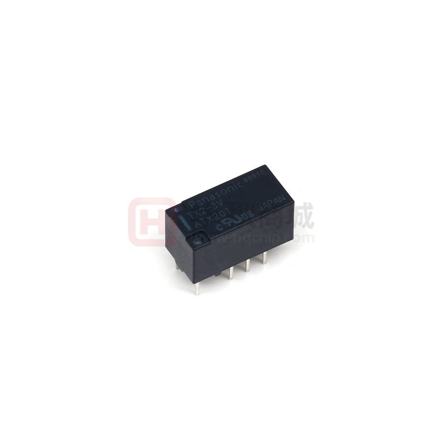
TX2-3V
TX2-4.5V
TX2-5V
TX2-6V
TX2-9V
TX2-12V
TX2-24V
2 coil latching
Part No.
TX2-LT-3V
TX2-LT-4.5V
TX2-LT-5V
TX2-LT-6V
TX2-LT-9V
TX2-LT-12V
TX2-LT-24V
Standard packing: Tube: 40 pcs.; Case: 1,000 pcs.
Note: Please add “-1” to the end of the part number for AgPd contacts (low level load).
2. Surface-mount terminal
1) Tube packing
Contact
arrangement
Nominal coil
voltage
2 Form C
3 V DC
4.5 V DC
5 V DC
6 V DC
9 V DC
12 V DC
24 V DC
Single side stable
Part No.
TX2SA-3V
TX2SA-4.5V
TX2SA-5V
TX2SA-6V
TX2SA-9V
TX2SA-12V
TX2SA-24V
2 coil latching
Part No.
TX2SA-LT-3V
TX2SA-LT-4.5V
TX2SA-LT-5V
TX2SA-LT-6V
TX2SA-LT-9V
TX2SA-LT-12V
TX2SA-LT-24V
Standard packing: Tube: 40 pcs.; Case: 1,000 pcs.
Note: Please add “-1” to the end of the part number for AgPd contacts (low level load).
2) Tape and reel packing
Contact
arrangement
Nominal coil
voltage
2 Form C
3 V DC
4.5 V DC
5 V DC
6 V DC
9 V DC
12 V DC
24 V DC
Single side stable
Part No.
TX2SA-3V-Z
TX2SA-4.5V-Z
TX2SA-5V-Z
TX2SA-6V-Z
TX2SA-9V-Z
TX2SA-12V-Z
TX2SA-24V-Z
2 coil latching
Part No.
TX2SA-LT-3V-Z
TX2SA-LT-4.5V-Z
TX2SA-LT-5V-Z
TX2SA-LT-6V-Z
TX2SA-LT-9V-Z
TX2SA-LT-12V-Z
TX2SA-LT-24V-Z
Standard packing: Tape and reel: 500 pcs.; Case: 1,000 pcs.
Notes: 1. Tape and reel packing symbol “-Z” is not marked on the relay. “X” type tape and reel packing (picked from 1/2/3/4-pin side) is also available.
2. Please add “-1” to the end of the part number for AgPd contacts (low level load).
RATING
1. Coil data
1) Single side stable
Nominal coil
voltage
3
Pick-up voltage
(at 20°C 68°F)
Drop-out voltage
(at 20°C 68°F)
V DC
4.5 V DC
5 V DC
6 V DC
9 V DC
12 V DC
24 V DC
75%V or less of
nominal voltage*
(Initial)
10%V or more of
nominal voltage*
(Initial)
Nominal operating
current
[±10%] (at 20°C 68°F)
46.7 mA
31 mA
28.1 mA
23.3 mA
15.5 mA
11.7 mA
5.8 mA
Coil resistance
[±10%] (at 20°C 68°F)
Nominal operating
power
Max. applied voltage
(at 20°C 68°F)
140 mW
150%V of
nominal voltage
64.3 Ω
145
178
257
579
1,028
4,114
Ω
Ω
Ω
Ω
Ω
Ω
2) 2 coil latching
Nominal coil
voltage
3
Set voltage
(at 20°C 68°F)
Reset voltage
(at 20°C 68°F)
V DC
4.5 V DC
5 V DC
6 V DC
9 V DC
12 V DC
24 V DC
75%V or less of
nominal voltage*
(Initial)
75%V or less of
nominal voltage*
(Initial)
Nominal operating
current
[±10%] (at 20°C 68°F)
Set coil
Reset coil
66.7 mA
66.7 mA
44.5 mA
40 mA
33.3 mA
22.2 mA
16.7 mA
8.3 mA
44.5 mA
40 mA
33.3 mA
22.2 mA
16.7 mA
8.3 mA
Coil resistance
[±10%] (at 20°C 68°F)
Set coil
45 Ω
Reset coil
45 Ω
101.2 Ω
125 Ω
180 Ω
405 Ω
720 Ω
2,880 Ω
101.2 Ω
125 Ω
180 Ω
405 Ω
720 Ω
2,880 Ω
Nominal operating
power
Set coil
Reset coil
200 mW
200 mW
Max. applied voltage
(at 20°C 68°F
150%V of
nominal voltage
*Pulse drive (JIS C 5442-1986)
–2–
ASCTB18E 201407-T
�TX
2. Specifications
Characteristics
Contact
Item
Arrangement
Initial contact resistance, max.
Contact material
Nominal switching capacity
Max. switching power
Max. switching voltage
Max. switching current
Min. switching capacity (Reference value)*1
Single side stable
Nominal operating
power
2 coil latching
Insulation resistance (Initial)
Between open contacts
Breakdown voltage
Between contact and coil
(Initial)
Between contact sets
Between open contacts
Surge breakdown
voltage (Initial)
Between contacts and coil
Rating
Electrical
characteristics
Temperature rise (at 20°C 68°F)
Operate time [Set time] (at 20°C 68°F)
Release time [Reset time] (at 20°C 68°F)
Functional
Destructive
Functional
Vibration resistance
Destructive
Mechanical
Electrical (Standard contact)
Shock resistance
Mechanical
characteristics
Expected life
Conditions for operation, transport and storage*2
Conditions
Max. operating speed (at rated load)
Unit weight
Specifications
2 Form C
Max. 100 mΩ (By voltage drop 6 V DC 1A)
Standard contact: Ag+Au clad,
AgPd contact (low level load): AgPd+Au clad (stationary), AgPd (movable)
Standard contact: 2 A 30 V DC, AgPd contact: 1 A 30 V DC (resistive load)
Standard contact: 60 W (DC), AgPd contact: 30 W (DC) (resistive load)
220V DC
Standard contact: 2 A, AgPd contact: 1 A
10μA 10mV DC
140 mW (3 to 24 V DC)
200 mW (3 to 24 V DC)
Min. 1,000MΩ (at 500V DC) Measurement at same location as “Initial breakdown voltage” section.
1,000 Vrms for 1min. (Detection current: 10mA)
2,000 Vrms for 1min. (Detection current: 10mA)
1,000 Vrms for 1min. (Detection current: 10mA)
1,500 V (10×160μs) (FCC Part 68)
2,500 V (2×10μs) (Telcordia)
Max. 50°C
(By resistive method, nominal coil voltage applied to the coil; contact carrying current: 2A.)
Max. 4 ms [Max. 4 ms] (Nominal coil voltage applied to the coil, excluding contact bounce time.)
Max. 4 ms [Max. 4 ms] (Nominal coil voltage applied to the coil, excluding contact bounce time.)
(without diode)
Min. 750 m/s2 (Half-wave pulse of sine wave: 6 ms; detection time: 10μs.)
Min. 1,000 m/s2 (Half-wave pulse of sine wave: 6 ms.)
10 to 55 Hz at double amplitude of 3.3 mm (Detection time: 10μs.)
10 to 55 Hz at double amplitude of 5 mm
Min. 108 (at 180 cpm)
Min. 105 (2 A 30 V DC resistive), 5×10⁵ (1 A 30 V DC resistive) (at 20 cpm)
Ambient temperature: –40°C to +85°C (up to 24 V coil) –40°F to +185°F (up to 24 V coil)
[–40°C to +70°C (48 V coil) –40°F to +158°F (48 V coil)];
Humidity: 5 to 85% R.H. (Not freezing and condensing at low temperature)
20 cpm
Approx. 2 g .071 oz
Notes: *1 This value can change due to the switching frequency, environmental conditions, and desired reliability level, therefore it is recommended to check this with the
actual load. (AgPd contact type is available for low level load switching [10V DC, 10mA max. level])
*2 Refer to “AMBIENT ENVIRONMENT” in GENERAL APPLICATION GUIDELINES.
REFERENCE DATA
1. Maximum switching capacity
2. Life curve
3. Mechanical life
Ratio against the rated voltage, %V
Tested sample: TX2-5V, 10 pcs.
Operating speed: 180 cpm
2.0
100
No. of operations ×104
Switching current, A
3.0
DC resistive load
1.0
0.5
0.4
0.3
50
30V DC
resistive load
30
20
10
0.2
100
90
80
Pick-up voltage
70
Max.
60
Min.
50
40
30
Drop-out voltage
20
Max.
Min.
10
0
20 30
0
50
100
200 300
Contact voltage, V
0
1.0
2.0
Switching current, A
10
100
1,000
No. of operations, ×104
10,000
4. Electrical life (2A 30V DC resistive load)
5. Coil temperature rise
Tested sample: TX2-5V, 6 pcs.
Operating speed: 20 cpm
Tested sample: TX2-5V, 6 pcs.
Point measured: Inside the coil
Ambient temperature: 25°C 77°F, 85°C 185°F
Change of contact resistance
100
90
90
80
Pick-up voltage
70
Max.
60
Min.
50
40
Drop-out voltage
30
Max.
20
80
70
60
50
40
Max.
30
Min.
+25°C +77°F
+85°C +185°F
60
50
40
30
2A
2A
20
0A
0A
20
Min.
10
0
70
Temperature rise, °C
100
Contact resistance, mΩ
Ratio against the rated voltage, %V
Change of pick-up and drop-out voltage
1
2
3
4 5 6 7 8 9
No. of operations, ×104
10
10
10
0
1
2
3
4 5 6 7 8 9
No. of operations, ×104
–3–
10
0
100 110
120 130 140 150
Coil applied voltage, %
ASCTB18E 201407-T
�TX
6-(2). Operate and release time (without diode)
7. Ambient temperature characteristics
Tested sample: TX2-5V, 10 pcs.
Tested sample: TX2-5V, 10 pcs.
Tested sample: TX2-5V, 5 pcs.
5
Operate and release time, ms
4
Max.
Min.
3
Max.
Min.
2
Operate and release time, ms
5
Operate time
Release time
Rate of change, %
6-(1). Operate and release time (with diode)
Operate time
Release time
4
Max.
Min.
3
–40 –20
2
1
0
0
20
Drop-out
voltage x
x
Pick-up voltage
20 40 60 80
Ambient temperature, °C
–20
Max.
Min.
1
0
40
–40
70
80
90
100 110 120
Coil applied voltage, %V
70
80
90
100 110 120
Coil applied voltage, %V
Tested sample: TX2-12V, 2 pcs.
Tested sample: TX2-12V, 2 pcs.
Insertion loss, dB
8-(2). High frequency characteristics
(Insertion loss)
Isolation, dB
8-(1). High frequency characteristics
(Isolation)
100
50
9. Malfunctional shock (single side stable)
Tested sample: TX2-5V, 6 pcs.
Z'
Y
Y'
Z XX'
Deenergized condition
Energized condition
Y
1000m/s 2
X
1000m/s2
Z
1000m/s2
1000m/s 2
Z'
1000m/s2
X'
1.0
0.8
0.6
0.4
1000m/s 2
Y'
0.2
10
100
Frequency, MHz
1,000
10
100
Frequency, MHz
1,000
Tested sample: TX2-12V, 6 pcs.
ON
ON
Pick-up voltage
0
–5
ON
Rate of change, %
Rate of change, %
5
Rate of change, %
10-(2). Influence of adjacent mounting
Tested sample: TX2-12V, 6 pcs.
Rate of change, %
10-(1). Influence of adjacent mounting
OFF OFF
5
Drop-out voltage
0
–5
OFF
0
2
4 6
8 10
.079 .157 .236 .315 .394
Inter-relay distance
ON
5
Pick-up voltage
0
ON
–5
ON
OFF
5
Drop-out voltage
0
OFF
–5
OFF
0
, mm inch
2
4 6
8 10
.079 .157 .236 .315 .394
Inter-relay distance
, mm inch
11. Pulse dialing test
Circuit
+
458 Ω
0.08
μF
48V DC
–
0.08
μF
458 Ω
Wire spring relay
4
TX
3
Ratio against the rated voltage, %V
Change of pick-up and drop-out voltage
Change of contact resistance
100
100
90
90
80
Pick-up voltage
70
Max.
Min.
60
50
40
Drop-out voltage
30
20
Max.
Min.
80
70
60
50
Max.
40
Min.
30
20
10
10
0
Contact resistance, mΩ
Tested sample: TX2-5V, 6 pcs.
(35 mA 48 V DC wire spring relay load)
10
20
30
40
No. of operation, ×104
50
0
10
20
30
40
No. of operations, ×104
50
Note: Data of surface-mount type are the same as those of PC board terminal type.
–4–
ASCTB18E 201407-T
�TX
DIMENSIONS (mm inch)
The CAD data of the products with a
CAD Data
mark can be downloaded from: http://industrial.panasonic.com/ac/e/
1. Standard PC board terminal and Self clinching terminal
Single side stable type
CAD Data
External dimensions
2 coil latching type
External dimensions
Standard PC board terminal
15.00
.591
Standard PC board terminal
7.40
.291
0.50
.020
1.15
.045
5.08
.200
3.50
.138
2.54
.100
0.65
.026
0.50
.020
1.15
.045
0.25
5.08 .010
.200
5.08
.200
2.54
.100
General tolerance: ±0.3 ±.012
PC board pattern
(Bottom view)
Schematic (Bottom view)
Single side stable
10.16
.400
2.54
.100
+
5.08
.200
–
8-1.0 dia.
8-.039 dia.
1
PC board pattern
(Bottom view)
12.7
.500
3 4 5
2.54
.100
10 9 8
10-1.0 dia.
10-.039 dia.
(Deenergized condition)
0.25
5.08 .010
.200
3.50
.138
Schematic (Bottom view)
2 coil latching
+
5.08
.200
12
8.20
.323
General tolerance: ±0.3 ±.012
Direction indication
Tolerance: ±0.1 ±.004
7.40
.291
15.00
.591
0.65
.026 8.20
.323
1
– 12
3 4 5 6
10 9 8 7
+
–
Direction indication
Tolerance: ±0.1 ±.004
(Reset condition)
2. Surface-mount terminal
CAD Data
External dimensions (General tolerance: ±0.3 ±.012)
Single side stable type
2 coil latching type
Type
15
.591
8.2
8.4
.323 .331
SA type
0.5
.020
0.65
.026
5.08
.200
15
.591
7.4
.291
5.08
.200
9.4±0.5
.370±.020
2.54
.100
Suggested mounting pad (Top view) (Tolerance: ±0.1 ±.004)
Single side stable type
2 coil latching type
7.4
.291
8.2
8.4
.323 .331
0.25
.010
0.5
.020
0.65
.026
5.08
.200
2.54
.100
5.08
.200
9.4±0.5
.370±.020
1
3.16 .039
.124
0.25
.010
5.08
.200
2.54
.100
5.08
1 .200
3.16 .039
.124
7.24
.285
2.54
.100
7.24
.285
Schematic (Top view)
Single side stable
–
+
12
10 9 8
1
3
4 5
Direction indication
(Deenergized condition)
2 coil latching
–
+
12
10 9 8 7
1
3
4 5 6
–
+
Direction indication
(Reset condition)
–5–
ASCTB18E 201407-T
�TX
NOTES
1. Packing style
1) The relay is packed in a tube with the
relay orientation mark on the left side, as
shown in the figure below.
Orientation (indicates PIN No.1) stripe
Stopper (gray)
Stopper (green)
2) Tape and reel packing (surface-mount
terminal type)
(1) Tape dimensions
2. Automatic insertion
To maintain the internal function of the
relay, the chucking pressure should not
exceed the values below.
Chucking pressure in the direction A:
4.9 N {500gf} or less
Chucking pressure in the direction B:
9.8 N {1 kgf} or less
Chucking pressure in the direction C:
9.8 N {1 kgf} or less
A
C
B
mm inch
1.5
Relay polarity bar .059
(Z type)
+0.1
0
+.004
0
dia.
dia. 2.0
.079
1.75
.069
4.0
.157
0.4
.016
C
A
Relays
B
11.5
.453
D
16.0 10.0 .394
.630
15.5
.610
24.0 ±0.3
±0.2
.945 ±.012 9.2±.008
.362
Tape coming out direction
Please chuck the
portion.
Avoid chucking the center of the relay.
In addition, excessive chucking pressure
to the pinpoint of the relay should be
avoided.
(2) Dimensions of plastic reel
mm inch
2.0
.079
13 dia.
.512 dia.
21 dia.
.827 dia.
For general cautions for use,
please refer to the “Cautions for
use of Signal Relays” or “General
Application Guidelines”.
380 dia.
14.961 dia.
80 dia.
3.150 dia.
–6–
ASCTB18E 201407-T
�


 工商网监
湘ICP备2023018690号
工商网监
湘ICP备2023018690号
