NJM2360
DC/DC CONVERTER CONTROL IC
■ GENERAL DESCRIPTION
The NJM2360 is a DC to DC converter control IC. Due to the
internalization of a high current output switch, 1.5A switching
operations are available. The NJM2360 is designed to be
incorporated in step-up, step-down and inverting applications with a
minimum number of external components. Output current is limited
by an external resistor.
■ PACKAGE OUTLINE
NJM2360D
NJM2360M
■ FEATURES
• Output Switch Current 1.5A(MAX)
• Operating Voltage
2.5V* to 40V
• Internal Over Current Limit Circuit
• Supply Voltage
V+
2.5V* to 40V
• Output Voltage
VOR
1.25V to 40V
• Oscillator Frequency fOSC
100Hz to 100kHz
• Package Outline
DIP8, DMP8
*Ta =25°C. At low temperature, the minimum voltage is 3.0V.
■ PIN CONFIGURATION
NJM2360D
NJM2360M
■ BLOCK DIAGRAM
Ver.2007-06-08
-1-
�NJM2360
■ ABSOLUTE MAXIMUM RATINGS
PARAMETER
(Ta = 25ºC)
SYMBOL
RATINGS
UNIT
Supply Voltage
V+
40
V
Comparator Input Voltage Range
VIR
-0.3 to V+
V
Power Dissipation
PD
(DIP8) 700
(DMP8) 600
Switch Current
ISW
1.5
A
Operating Temperature Range
Topr
-40 to + 85
ºC
Storage Temperature Range
Tstg
-40 to +125
ºC
(note1)
mW
mW
(note 1) At on PC board
■ ELECTRICAL CHARACTERISTICS
● DC Characteristics (V+ = 5V, Ta = 25ºC)
PARAMETER
SYMBOL
TEST CONDITION
MIN.
TYP.
MAX.
UNIT
-
2.4
3.5
mA
ICC
+
5V ≤ V ≤ 40V, CT = 0.001µF
+
SI = V , INVIN > Vth, ES = GND
Ichg
5V ≤ V+ ≤ 40V
20
35
50
µA
Discharge Current
Idischg
+
150
200
250
µA
Voltage Swing
VOSC
-
0.5
-
VP-P
-
6
-
-
250
300
350
mV
Operating Current
Oscillator
Charge Current
5V ≤ V ≤ 40V
+
Discharge to Charge Current Ratio
Idischg/Ichg
SI = V
Peak Current Sense Voltage
VIPK(sense)
Ichg = Idischg
Saturation Voltage 1
VCE(sat) 1
Darlington Connection (CS = CD)
ISW = 1.0A
-
1.0
1.3
V
Saturation Voltage 2
VCE(sat) 2
ISW = 1.0A, IC(driver) = 50mA
(Forced β ・=・ 20)
-
0.5
0.7
V
35
120
-
-
-
10
-
nA
1.18
1.25
1.32
V
-
40
400
nA
Output Switch (Note 2)
DC Current Gain
hFE
ISW = 1.0A, VCE = 5.0V
Collector Off-State Current
IC(off)
VCE = 40V
Comparator
Threshold Voltage
Vth
Input Bias Current
IIB
VIN = 0V
Note 2 : Output switch tests are performed under pulsed conditions to minimize power dissipation.
-2-
Ver.2007-06-08
�NJM2360
■ TYPICAL APPLICATION
1. Step-Up Converter
*D1 : SBD (EK14)
2. Step-Down Converter
*D1 : SBD (EK14)
Ver.2007-06-08
-3-
�NJM2360
■ TYPICAL APPLICATIONS
3. Step-Up Converter (High Current)
4. Step-Down Converter (High Current)
5. Inverting Converter
*D1 : SBD (EK14)
-4-
Ver.2007-06-08
�NJM2360
Fig. 1 Block Diagram
Fig. 2 Timing Chart
■ POWER DISSIPATION VS. TEMPERATURE
Ver.2007-06-08
-5-
�NJM2360
■ TYPICAL CHARACTERISTICS
Oscillator Frequency vs. Timing Capacitor
Switching Time vs. Timing Capacitor
Operating Current vs. Operating Voltage
Switch Saturatin Voltage 2
vs. Collector Current (β・=・20)
Switch Saturation Voltage 1
vs. Collector Current (Darlington)
Saturation Voltage 1 vs. Temperature
-6-
Ver.2007-06-08
�NJM2360
■ TYPICAL CHARACTERISTICS
Saturation Voltage 2 vs. Temperature
Operating Current vs. Temperature
Discharge to Charge Current Ratio
vs. Temperature
Threshold Voltage vs. Temperature
Ver.2007-06-08
-7-
�NJM2360
■ TYPICAL CHARACTERISTICS (Application)
1. Step-Up Converter
Output Voltage vs. Input Voltage
Output Voltage vs. Output Current
2. Step-Down Converter
Output Voltage vs. Input Voltage
Output Voltage vs. Output Current
[CAUTION]
The specifications on this databook are only
given for information , without any guarantee
as regards either mistakes or omissions. The
application circuits in this databook are
described only to show representative usages
of the product and not intended for the
guarantee or permission of any right including
the industrial rights.
-8-
Ver.2007-06-08
�
很抱歉,暂时无法提供与“NJM2360M-TE1”相匹配的价格&库存,您可以联系我们找货
免费人工找货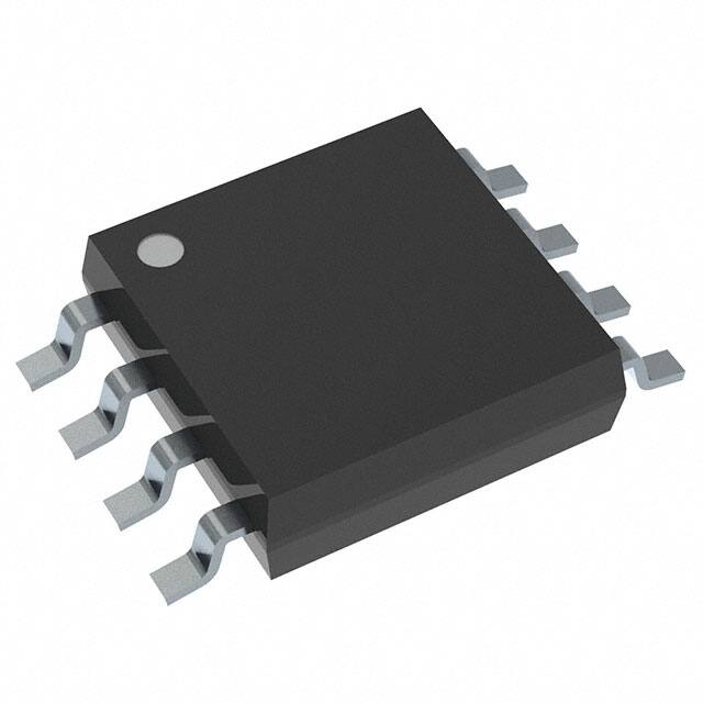


 工商网监
湘ICP备2023018690号
工商网监
湘ICP备2023018690号
