NJM2863/64
Ultra Low Noise Low Dropout Voltage Regulator
! GENERAL DESCRIPTION
The NJM2863/64 is a low dropout voltage regulator designed for
VCO Applications.
Advanced Bipolar technology achieves ultra low noise, high ripple
rejection and low quiescent current.
! PACKAGE OUTLINE
NJM2863F/64F
! FEATURES
" High Ripple Rejection
75dB typ. (f=1kHz,Vo=3V Version)
" Output capacitor with 1.0µF ceramic capacitor
" Output Noise Voltage
Vno=19µVrms typ. (Cp=0.01µF, Co=1.0µF(Ceramic))
Vno=12µVrms typ. (Cp=0.1µF, Co=10µF(Tantalum))
" Output Current
Io(max.)=100mA
" High Precision Output
Vo±1.0%
" Low Dropout Voltage
0.10V typ. (Io=60mA)
" ON/OFF Control
(Active High)
" Internal Short Circuit Current Limit
" Internal Thermal Overload Protection
" Bipolar Technology
" Package Outline
SOT-23-5
! PIN CONFIGURATION
5
4
5
1.CONTROL
2.GND
3.NOISE BYPASS
4.VOUT
1 2 3
5.VIN
NJM2863F
4
1 2 3
1.VIN
2.GND
3.CONTROL
4.NOISE BYPASS
5.VOUT
NJM2864F
! EQUIVALENT CIRCUIT
VOUT
VIN
Control
Thermal
Protection
Bandgap
Reference
Noise
Bypass
GND
Ver.2006-02-20
-1-
�NJM2863/64
! OUTPUT VOLTAGE RANK LIST
Device Name
VOUT
2.1V
NJM286×F21
2.5V
NJM286×F25
2.7V
NJM286×F27
2.8V
NJM286×F28
2.85V
NJM286×F285
Device Name
NJM286×F29
NJM286×F03
NJM286×F33
NJM286×F05
VOUT
2.9V
3.0V
3.3V
5.0V
! ABSOLUTE MAXIMUM RATINGS
PARAMETER
SYMBOL
Input Voltage
VIN
Control Voltage
VCONT
(Ta=25°C)
RATINGS
UNIT
+14
V
+14(*1)
V
350(*2)
Power Dissipation
PD
SOT-23-5
mW
200(*3)
Operating Temperature
Topr
−40 ∼ +85
°C
Storage Temperature
Tstg
−40 ∼ +125
°C
(*1): When input voltage is less than +14V, the absolute maximum control voltage is equal to the input voltage.
(*2): Mounted on glass epoxy board based on EIA/JEDEC. (114.3x76.2x1.6mm: 2Layers)
(*3): Device itself.
! ELECTRICAL CHARACTERISTICS (VIN=Vo+1V, CIN=0.1µF, Co=1.0µF, Cp=0.01µF, Ta=25°C)
PARAMETER
SYMBOL
TEST CONDITION
MIN. TYP.
Output Voltage
Vo
Io=30mA
-1.0%
−
Quiescent Current
IQ
Io=0mA, except Icont
120
−
Quiescent Current
VCONT=0V
IQ(OFF)
−
−
at Control OFF
Output Current
Io
Vo-0.3V
100
130
Line Regulation
∆Vo/∆VIN VIN=Vo+1V ∼ Vo+6V, Io=30mA
−
−
Load Regulation
∆Vo/∆Io Io=0 ∼ 100mA
−
−
Io=60mA
0.10
Dropout Voltage
∆VI−O
−
ein=200mVrms,f=1kHz, Io=10mA,
Ripple Rejection
RR
75
−
Vo=3V Version
Average Temperature
Coefficient of Output
∆Vo/∆Ta Ta=0∼85°C, Io=10mA
± 50
−
Voltage
f=10Hz∼80kHz, Io=10mA, Cp=0.01µF,
Output Noise Voltage1
VNO1
19
−
Co=1.0µF (Ceramic), Vo=3V Version
f=10Hz∼80kHz, Io=10mA, Cp=0.1µF,
Output Noise Voltage2
VNO2
12
Co=10µF (Tantalum), Vo=3V Version
Control Voltage for
1.6
VCONT(ON)
−
ON-state
Control Voltage for
VCONT(OFF)
−
−
OFF-state
The above specification is a common specification for all output voltages.
Therefore, it may be different from the individual specification for a specific output voltage.
-2-
MAX.
+1.0%
180
UNIT
V
µA
100
nA
−
0.10
0.03
0.18
mA
%/V
%/mA
V
−
dB
−
ppm/°C
−
µVrms
µVrms
−
V
0.6
V
Ver.2006-02-20
�NJM2863/64
! TEST CIRCUIT
A
IIN
VIN
VOUT
1.0µF
(ceramic)
VIN
0.1µF
A
V VCONT
Ver.2006-02-20
ICONT
NJM2863/64
IOUT V VOUT
NOISE
CONTROL BYPASS
GND
Cp=0.01µF
-3-
�NJM2863/64
! TYPICAL APPLICATION
1 In the case where ON/OFF Control is not required:
VIN
VIN
VOUT
VOUT
1.0µF
0.1µF
NJM2863/64
R
(0∼300kΩ)
NOISE
CONTROL BYPASS
Cp=0.01µF
GND
Connect control terminal to VIN terminal
2 In use of ON/OFF CONTROL:
VIN
VIN
VOUT
VOUT
1.0µF
NJM2863/64
0.1µF
R
NOISE
CONTROL BYPASS
GND
Cp=0.01µF
State of control terminal:
•“H”→ output is enabled.
•“L” or “open” → output is disabled.
%Noise bypass Capacitance Cp
Noise bypass capacitance Cp reduces noise generated by band-gap reference circuit. Noise level and ripple
rejection will be improved when larger Cp is used. Use of smaller Cp value may cause oscillation.
Use the Cp value of 0.01µF greater to avoid the problem.
%In the case of using a resistance "R" between VIN and control.
The current flow into the control terminal while the IC is ON state (ICONT) can be reduced when a pull up resistance
"R" is inserted between VIN and the control terminal.
The minimum control voltage for ON state (VCONT (ON)) is increased due to the voltage drop caused by ICONT and the
resistance "R". The ICONT is temperature dependence as shown in the "Control Current vs. Temperature"
characteristics. Therefore, the resistance "R" should be carefully selected to ensure the control voltage exceeds the
VCONT (ON) over the required temperature range.
-4-
Ver.2006-02-20
�NJM2863/64
! POWER DISSIPATION vs. AMBIENT TEMPERATURE
NJM2863/64F Power Dissipation
(Topr=-40~+85℃,Tj=125℃,PD=200mW(Ta≦25℃))
Power Dissipation PD(mW)
500
On Board(114.3×76.2×1.6mm, FR-4)
400
300
Device itself
200
100
0
-50
-25
0
25
50
75
100
Ambient Temperature Ta(℃)
Ver.2006-02-20
-5-
�NJM2863/64
! ELECTRICAL CHARACTERISTICS
NJM2863/64_3.0V
Output Voltage v.s. Input Voltage
3.2
NJM2863/64_3.0V
Output Voltage vs. Output Current
4
o
@:Ta=25 C
Co=1.0µF(Ceramic)
Cp=0.01µF
3.5
3
Output Voltage :Vo [V]
Output Voltage :Vo [V]
3.1
Io=0A
3
2.9
Io=30mA
2.5
2
1.5
1
o
@:Ta=25 C
V IN=4V
Co=1.0µF(Ceramic)
Cp=0.01µF
2.8
Io=100mA
0.5
2.7
0
2.7
2.8
2.9
3
3.1
3.2
3.3
3.4
0
50
Input Voltage :Vin [V]
NJM2863/64_3.0V
Ground Pin Current vs. Output Voltage
20
150
200
NJM2863/64_3.0V
Dropout Voltage vs. Output Current
0.3
o
@:Ta=25oC
V IN=4V
Co=1.0µF(Ceramic)
Cp=0.01µF
@:Ta=25 C
Co=1.0µF(Ceramic)
Cp=0.01µF
0.25
15
Dropout Voltage :dVi-o [V]
Ground Pin Current :Ignd [mA]
100
Output Current :Io [mA]
10
5
0.2
0.15
0.1
0.05
0
0
0
20
40
60
80
100
120
0
20
Output Current :Io [mA]
NJM2863/64_3.0V
Control Current v.s. Control Voltage
30
40
60
80
100
120
Output Current :Io [mA]
NJM2863/64_3.0V
Output Voltage v.s. Control Voltage
4
o
@:Ta=25 C
V IN=4.0V
Co=1.0µF(Ceramic)
Cp=0.01µF
Io=30mA
Output Voltage :Vo [V]
Control Current :Icont [ µ A]
25
o
@:Ta=25 C
V IN=4.0V
Co=1.0µF(Ceramic)
Cp=0.01µF
Io=30mA
3.5
20
15
Rc=50kΩ
Rc=0Ω
10
3
Rc=0Ω
2.5
Rc=50kΩ
2
Rc=100kΩ
1.5
1
5
0.5
Rc=100kΩ
0
0
0
0.5
1
1.5
2
2.5
3
Control Voltage :Vcont [V]
-6-
3.5
4
0
0.5
1
1.5
2
2.5
3
Control Voltage :Vcont [V]
Ver.2006-02-20
�NJM2863/64
! ELECTRICAL CHARACTERISTICS
NJM2863_3.0V
Load Regulation vs. Output Current
NJM2863_3.0V
Peak Output Current vs. Input Voltage
0
o
@:Ta=25 C
Co=1.0uF(Ceramic)
Cp=0.01uF
200
Peak Output Current :Io MAX [mA]
Load Regulation :dVo/dIo [mV]
-10
-20
-30
-40
@:Ta=25 oC
VIN=4V
Co=1.0uF(Ceramic)
Cp=0.01uF
-50
150
100
50
0
0
50
100
150
4
6
Output Current :Io [mA]
NJM2863_3.0V
Quiescent Current v.s. Input Voltage
2000
@:Ta=25oC
Output is open.
Co=1.0uF(Ceramic)
Cp=0.01uF
including Icont
12
1000
500
0
200
150
100
50
0
0
5
10
1p
15
10p
100p
1000p
0.01µ
0.1µ
Noise Bypass Capacitor : Cp(F)
Input Voltage :Vin [V]
NJM2863/64_3.0V
Output Noise Voltage vs. Output Current
100
14
@:Ta=25 oC
V IN=4V
Co=1 µF(Ceramic)
Io=10mA
250
Output Noise Voltage : Vn( µ
µVrms)
Quiescent Current : Iq [µ A]
10
NJM2863/64_3.0V
Output Noise Voltage vs. Noise Bypass Capacitor
300
1500
8
Input Voltage :Vin [V]
NJM2863/64_3.0V
Ripple Rejection Ratio v.s. Frequency
90
o
80
Io=10mA
80
Ripple Rejection Ratio :RR [dB]
Output Noise Voltage :Vn [ µ Vrms]
@:Ta=25 C
V IN=4.0V
LPF:80kHz
60
40
Co=1.0µF(Ceramic)
Cp=0.01µF
20
70
Io=30mA
60
50
40
@:Ta=25 oC
V IN=4.0V
ein=200mVrms
Co=1.0 µF(Ceramic)
Cp=0.01µF
30
0
0.001
Co=10µF(Tantalum)
Cp=0.1µF
0.01
0.1
1
Output Current :Io [mA]
Ver.2006-02-20
10
20
100
10
100
1k
10k
100k
Frequency :f [Hz]
-7-
�NJM2863/64
! ELECTRICAL CHARACTERISTICS
NJM2863/64_3.0V
Ripple Rejection vs. Output Current
100
NJM2863/64_3.0V
Equivalent Series Resistance vs. Output Current
100
o
f=1kHz
Ripple Rejection : RR (dB)
80
70
60
50
f=10kHz
40
@:Ta=25o C
V IN=4V
ein=200mVrms
Co=1.0 µF(Ceramic)
Cp=0.01µF
30
20
0.001
0.01
0.1
1
10
@:Ta=25 C
V IN=4V
Co=1.0µF(Ceramic)
Cp=0.01µF
Equivalent Series Resistance :ESR [ohm]
90
100
10
STABLE REGION
1
0.1
0.02
0.001
Output Current : Io(mA)
0.01
0.1
1
NJM2863/64_3.0V
Dropout Voltage v.s. Temperature
100
NJM2863_3.0V
Output Voltage v.s. Tem perature
0.3
3.1
@:Io=60mA
Co=1.0µF(Ceramic)
Cp=0.01µF
@:V IN=4.0V
Io=30mA
Co=1.0µF(Ceramic)
Cp=0.01µF
0.25
3.05
Output Voltage :Vo [V]
Dropout Voltage :dVi-o [V]
10
Output Current :Io [mA]
0.2
0.15
0.1
3
2.95
0.05
0
2.9
-50
0
50
100
150
-50
0
o
100
150
Temperature :Ta [ C]
NJM2863/64_3.0V
Control Voltage v.s. Temperature
NJM2863/64_3.0V
Control Current v.s. Temperature
2
10
@:VIN=4.0V
Output is open.
Co=1.0µF(Ceramic)
Cp=0.01µF
@:VIN=4V
Output is open.
Co=1.0uF(Ceramic)
Cp=0.01uF
V CONT=1.6V
8
1.5
Control Current : ICONT (µ
µ A)
Control Voltage :Vcont-off [V]
50
o
Temperature :Ta [ C]
1
0.5
6
4
2
0
0
-50
0
50
100
o
Temperature :Ta [ C]
-8-
150
-50
0
50
100
150
o
Temperature Ta ( C)
Ver.2006-02-20
�NJM2863/64
! ELECTRICAL CHARACTERISTICS
NJM2863_3.0V
Short Circuit Current v.s. Temperature
NJM2863_3.0V
Quiescent Current v.s. Temperature
200
300
Short Circuit Current :Isc [mA]
250
Quiescent Current : Iq [µ A]
@:V IN=4.0V
Output is short to ground.
Co=1.0µF(Ceramic)
Cp=0.01µF
@:VIN=4.0V
Output is open.
Co=1.0µF(Ceramic)
Cp=0.01µF
200
150
100
150
100
50
50
0
0
-50
0
50
100
-50
150
0
100
150
Temperature :Ta [ C]
NJM2863_3.0V
Line Regulation v.s. Temperature
NJM2863_3.0V
Load Regulation v.s. Temperature
0.2
0.03
@:V IN=4.0-9.0V
Io=30mA
Co=1.0µF(Ceramic)
Cp=0.01µF
0.1
0
-0.1
-0.2
-50
@:V IN=4.0V
Io=0-60mA
Co=1.0µF(Ceramic)
Cp=0.01µF
0.025
Load Regulation :dVo/dIo [%/mA]
Line Regulation :dVo/dVin [%/V]
50
o
o
Temperature :Ta [ C]
0.02
0.015
0.01
0.005
0
0
50
100
150
o
-50
0
50
100
150
o
Temperature :Ta [ C]
Temperature :Ta [ C]
NJM2863_3.0V
Output Voltage v.s. Tem perature
3.5
3
Output Voltage :Vo [V]
2.5
2
1.5
1
@:VIN=4.0V
Io=30mA
Co=1.0µF(Ceramic)
Cp=0.01µF
0.5
0
-50
0
50
100
150
200
o
Temperature :Ta [ C]
Ver.2006-02-20
-9-
�NJM2863/64
! ELECTRICAL CHARACTERISTICS
NJM2863_3V
ON/OFF Transient Response
NJM2863_3V
ON/OFF Transient Response without Load
6
15
7
10
6
5
5
15
10
Control Voltage
4
0
Output Voltage
3
-5
2
-10
@:Ta=25oC
VIN=4V
Co=1µF
Cp=0.01µF
Io=0mA
1
0
-1
0
1
2
3
Time : t [S]
4
Output Voltage : Vo [V]
Output Voltage : Vo [V]
5
Control Voltage : Vo [V]
Control Voltage
5
4
0
Output Voltage
3
-5
2
-10
o
-15
1
-20
0
-25
-1
@:Ta=25 C
VIN=4V
Co=1µF
Cp=0.01µF
Io=30mA
-15
-20
-25
0
5
Control Voltage : Vo [V]
7
4
8
12
Time : t [mS]
16
20
NJM2863_3V
Load Transient Response
NJM2863_3V
Line Transient Response
3.1
7
3.1
3.08
6
3.08
150
100
3.04
4
3.02
3
3
2
Output Voltage
2.98
3.06
50
3.04
0
-50
3.02
Output Voltage
-100
3
1
2.98
2.96
0
2.96
2.94
0
40
80
120
Time : t [ µS]
160
-1
200
-150
o
@:Ta=25 C
VIN=4V
Co=1µF(Ceramic)
Cp=0.01µF
o
@:Ta=25 C
Co=1µF
Cp=0.01µF
Io=30mA
Output Current : Io [mA]
5
Input Voltage
Output Voltage : Vo [V]
Output Voltage : Vo [V]
3.06
Input Voltage : V IN [V]
Output Current
-200
2.94
0
40
80
120
Time : t [ µS]
160
-250
200
[CAUTION]
The specifications on this databook are only
given for information , without any guarantee
as regards either mistakes or omissions. The
application circuits in this databook are
described only to show representative usages
of the product and not intended for the
guarantee or permission of any right including
the industrial rights.
- 10 -
Ver.2006-02-20
�
很抱歉,暂时无法提供与“NJM2863F05-TE1”相匹配的价格&库存,您可以联系我们找货
免费人工找货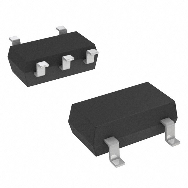


 工商网监
湘ICP备2023018690号
工商网监
湘ICP备2023018690号
