Series JB
Toggles
Illuminated Low Profile Process Sealed Tactiles
Rockers
General Specifications
Electrical Capacity (Resistive Load)
Low/Logic Level: 50mA @ 24V DC maximum for Standard Operating Force models 125mA @ 24V DC maximum for High Operating Force models
Pushbuttons
Other Ratings
Contact Resistance: Insulation Resistance: Dielectric Strength: Mechanical Life: Electrical Life: Nominal Operating Force: Total Travel:
Programmable Illuminated PB
Standard Operating Force
High Operating Force
50 milliohms maximum 50 milliohms maximum 500 megohms minimum @ 250V DC 500 megohms minimum @ 250V DC 250V AC minimum for 1 minute minimum 250V AC minimum for 1 minute minimum 5,000,000 operations minimum 1,000,000 operations minimum 5,000,000 operations minimum 1,000,000 operations minimum 1.76N for JB15L 2.65N for JB15HL & JB15HB .010” (.254mm) .012” (.300mm)
Keylocks
Materials & Finishes
Actuator: Case: Seal: Base: Movable Contacts: Stationary Contacts: Terminals:
Polyacetal for Short; Glass fiber reinforced PBT for Extended Glass fiber reinforced polyamide (UL94V-0) Nitrile butadiene rubber Glass fiber reinforced PBT (UL94V-0) Beryllium copper with silver plating Brass with silver plating Brass with silver plating
Slides
Rotaries
Environmental Data
Tactiles
J
Operating Temperature Range: Humidity: Vibration: Shock:
–25°C through +70°C (–13°F through +158°F) 90 ~ 95% humidity for 240 hours @ 40°C (104°F) 10 ~ 55Hz with peak-to-peak amplitude of 1.5mm traversing the frequency range & returning in 1 minute; 3 right angled directions for 2 hours 50G (490m/s2) acceleration (tested in 6 right angled directions, with 5 shocks in each direction)
Tilt
PCB Processing
Soldering: Cleaning:
Wave Soldering recommended. See Profile A in Supplement section. Manual Soldering: See Profile A in Supplement section. Automated cleaning. See Cleaning specifications in Supplement section.
Touch
Standards & Certifications
Flammability Standards:
UL94V-0 rated case & base The JB Series tactiles have not been tested for UL recognition or CSA certification. These switches are designed for use in a low-voltage, low-current, logic-level circuit. When used as intended in a logic-level circuit, the results do not produce hazardous energy.
Supplement
Accessories
Indicators
J28
www.nkk.com
�Illuminated Low Profile Process Sealed Tactiles
Series JB
Toggles
Choice of dimensions from PCB to top of cap adds to design flexibility. Bright, full-face illumination with red, green, or yellow LEDs for attractive, functional panel layouts. Higher operating force type provides more pronounced operating feel. Dome contact gives crisp tactile feedback to positively indicate circuit transfer and assures high reliability and long life of up to 5,000,000 operations. Rubber seal construction prevents contact contamination and allows automated soldering and cleaning. Slanted terminals provide a spring type action which ensures secure mounting and prevents dislodging during wave soldering. Molded-in terminals are part of the sealed construction which allows automated soldering and cleaning. Terminal spacing conforms to standard .100” (2.54mm) PCB grid.
Actual Size
Common Bus Matrix
These single pole, single throw switches can be used in a keyboard matrix and, using strapped terminals, achieve a common bus electrical configuration on a single-sided PC board.
5
1 2
X-Y Matrix
These single pole, single throw switches can be arranged on a single-sided PC board matrix with strapped terminals to achieve an X-Y type electrical interconnection.
1 2 3
J
9
3
13
Keys (Switches)
Keys (Switches)
4
7 8
6 11 8 12
2
7 8
9
9
A
0
B
A
0
B
1 2 7
7
= ON
5 4 3
Red = PCB Trace
Black = Switch Circuit
www.nkk.com J29
Supplement
Accessories
3
6
Indicators
4
5
6
10
1 2 3 4 5 6 7 8 9 0 A B
P C Te r m i n a t i o n s 1 2 3 4 5 6 7 8 9 10 11 12 13
1
4 5 6
P C Te r m i na t i ons 1 234 567 1 2 3 4 5 6 7 8 9 0 A B = ON
Touch
Tilt
Tactiles
Slides
Rotaries
Keylocks
Programmable Illuminated PB
Pushbuttons
Rockers
Distinctive Characteristics
�Series JB
Toggles
Illuminated Low Profile Process Sealed Tactiles
TYPICAL SWITCH ORDERING EXAMPLE
JB
Pole & Circuit
15 SPST OFF (ON) ( ) = Momentary
15
L
P
Terminals
C
JC
Cap Types & Colors
Flat Cap Colors B C E F Translucent White Red Yellow Green
Programmable Illuminated PB
Pushbuttons
Rockers
Actuators
L B Short Extended (H operating force only)
P
Straight PC
LED Colors Operating Force
No Code H Standard (L actuator only) High C E F Red Yellow Green
Flat Cap Lens/Diffuser Colors JB JC JE JF Clear/White Clear/Red Clear/Yellow Clear/Green
Rotaries
Keylocks
For JC, JE & JF, diffuser color must match LED color Framed Cap Button/Frame Colors DESCRIPTION FOR TYPICAL ORDERING EXAMPLE BB BC BE Flat Cap with Clear Lens and Red Diffuser Standard Operating Force Straight PC Terminals BF BH White/White White/Red White/Yellow White/Green White/Gray
Slides
JB15LPC-JC
Tactiles
J
Red LED Short Actuator SPST OFF-(ON) Circuit
Touch
Tilt
POLE & CIRCUIT
Indicators
Actuator Position ( ) = Momentary Pole & Throw SPST Normal Model JB15 OFF (ON) Down
Switch Throw & Schematic
LED Schematic Notes: Terminal numbers are shown on switch. LED circuit is isolated & requires external power source.
Accessories
1
3
(+) (-)
SPST
2
4
Supplement
J30
www.nkk.com
�Illuminated Low Profile Process Sealed Tactiles
OPERATING FORCE No Code
Standard Nominal Operating Force
1.76N Available with short actuator only (code L)
Series JB
High Nominal Operating Force
2.65N Available with both short and extended actuators
Toggles
(11.2) .441 (12.7) .500 (3.1) .122 (12.7) Typ .500 (12.7) .500 (3.1) .122
3+
ACTUATORS L
Short Actuator
(4.9) .193 (12.7) Typ .500
(3.0) .118
Custom keyboards can be designed with caps installed through a panel cutout (illustration with cap AT4060).
B
Extended Actuator
(3.3) .130 (8.4) .331 (3.2) .126 (14.7) .579
High operating force only
Custom keyboards can be designed with caps installed through a panel cutout (illustration with cap AT4076).
P
Straight PC Terminals
(0.8) Typ .031 (0.3) Typ .012
J
1
(5.08) .200 (3.1) Typ .122
(5.08) Typ .200 (2.54) Typ .100
(10.16) .400
4 2
Further details in Typical Switch Dimensions
C L
(1.0) Dia Typ .039 (5.08) .200
Color Forward Peak Current Continuous Forward Current Forward Voltage Reverse Peak Voltage Current Reduction Rate Above 25°C Ambient Temperature Range I FM IF VF VRM ∆I F
Red 25mA 20mA 2.0V 4V
Yellow 25mA 20mA 2.2V 4V 0.42mA/°C –25°C ~ +70°C
Green 25mA 20mA 2.1V 4V
LED polarity markings are on the bottom of the switch. The electrical specifications shown here are determined at a basic temperature of 25°C. If the source voltage exceeds the rated voltage, a ballast resistor is required. The resistor value can be calculated by using the formula in the Supplement section.
www.nkk.com
J31
Supplement
Accessories
Indicators
LEDs are supplied as an integral part of illuminated devices and are not available separately.
C
E
F
Touch
LED COLORS & SPECIFICATIONS
Tilt
Tactiles
TERMINALS
Slides
Rotaries
Keylocks
Programmable Illuminated PB
Pushbuttons
Rockers
H
�Series JB
Toggles
Illuminated Low Profile Process Sealed Tactiles
SNAP-ON CAPS
AT4135 Flat
Rockers
Cap Color Codes:
B C
Translucent White Red
Material: Polycarbonate
E F
Yellow Green
(7.3) .287
Pushbuttons
Finish: Frosted
(12.0) Sq .472
Programmable Illuminated PB
AT4060 Flat
Lens/Diffuser Color Codes:
(6.3) .248
Framed: AT4076 Button with Frame
Translucent Button/Frame Color Codes:
(6.3) .248
(12.0) Sq .472
(12.3) Sq .484
JB JC JE JF
Clear/Translucent White Clear/Red
Transparent Clear Lens
BB BC BE BF BH
White/White White/Red White/Yellow White/Green White/Gray
Button Finish: Frosted
Keylocks
Translucent Clear Button Translucent White Filter Opaque White or Colored Frame
Clear/Yellow Clear/Green
Translucent White or Colored Diffuser White Frame
Rotaries
Slides
Material: Polycarbonate
Lens Finish: Glossy
Material: Polycarbonate
TYPICAL SWITCH DIMENSIONS
Flat Snap-on Cap
Tactiles
J
(8.5) .335
(0.4) .016
Tilt
Short Actuator
(12.0) Sq .472 (6.3) .248 (7.0) (4.2) .276 .165
(11.5) .453 (3.1) .122
Extended Actuator
(6.3) .248 (7.3) .287 (0.4) .016 (7.4) .291
(11.5) .453 (0.3) Typ .012 (3.1) .122
(10.0) Sq .394 (0.8) Typ .031 (5.08) .200
Touch
JB15LPC-JC
Spring action terminals conform to .100” (2.54mm) PCB spacing
Framed Snap-on Cap
Indicators
(10.0) .394 (0.4) .016
Accessories
(10.0) .394
Short Actuator
(6.3) .248 (7.0) .276 (4.2) .165
(11.5) .453 (3.1) .122
Extended Actuator
(6.3) .248 (7.3) .287 (0.4) .016 (7.4) .291
(11.5) .453
(10.0) Sq .394 (0.8) Typ .031 (5.08) .200
Supplement
(12.3) Sq .484
(0.3) Typ .012 (3.1) .122
JB15HBPC-BC
Spring action terminals conform to .100” (2.54mm) PCB spacing
www.nkk.com
J32
�Illuminated Low Profile Process Sealed Tactiles
LEGENDS
Series JB
Toggles
NKK Switches can provide custom legends for caps. Contact factory for more information.
Suggested Printable Area for Cap, Lens, or Button
Recommended Methods: Laser Etch, Screen Print or Pad Print Epoxy based ink is recommended. Laser Etch or Pad Print Epoxy based ink is recommended.
PW
R
(10.0) Sq .394
(10.48) Sq .412 (12.0) Sq .472
(0.76) Typ .030
(10.48) Sq .412 (12.0) Sq .472
(0.76) Typ .030
(6.94) .273 (8.46) .333
(0.76) Typ .030
Suggested Printable Area for Film Insert
Slides
Lens (20.0) R .787 Film Insert
J
(8.38) Typ .330 (9.9) .390
Translucent White or Colored Diffuser Frame
Film Insert: Clear Polyester 7 mil maximum thickness
Indicators
www.nkk.com
J33
Supplement
Accessories
Touch
Shaded area is printable area.
Tilt
Tactiles
Rotaries
Shaded areas are printable areas.
Keylocks
Programmable Illuminated PB
Pushbuttons
Rockers
N O
P U
O N
�
很抱歉,暂时无法提供与“JB15HLPC-JB”相匹配的价格&库存,您可以联系我们找货
免费人工找货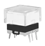


 工商网监
湘ICP备2023018690号
工商网监
湘ICP备2023018690号
