NTE5111A thru NTE5166A
Zener Diode, 5 Watt
5% Tolerance
Features:
D Zener Voltage: 3.3V to 200V
D High Surge Current Capability
Absolute Maximum Ratings:
DC Power Dissipation (TL = +75C, Lead Length = 3/8”), PD . . . . . . . . . . . . . . . . . . . . . . . . . . . . . 5W
Derate Above 75C . . . . . . . . . . . . . . . . . . . . . . . . . . . . . . . . . . . . . . . . . . . . . . . . . . . . . . 40mW/C
Forward Voltage (IF = 1A), VF . . . . . . . . . . . . . . . . . . . . . . . . . . . . . . . . . . . . . . . . . . . . . . . . . . . . . . . 1.2V
Operating Junction Temperature Range, TJ . . . . . . . . . . . . . . . . . . . . . . . . . . . . . . . . . . −55 to +150C
Storage Temperature Range, Tstg . . . . . . . . . . . . . . . . . . . . . . . . . . . . . . . . . . . . . . . . . . −55 to +150C
Electrical Characteristics: (TA = +25C unless otherwise specified)
Max Reverse
Leakage Current
Nominal
Zener
Voltage
VZ @ IZT
(Note 1)
Max Surge
Current
ir
(Note 2)
Max
Voltage
Regulation
VZ
(Note 3)
Test
Current
IZT
Max
Regulator
Current
IZM
ZZT @ IZT
(Note 1)
ZZK @ IZK = 1mA
(Note 1)
IR
Volts
mA
A
Volts
Amps
Volt
mA
NTE5111A
3.3
380
3.0
400
300
1
20
0.85
1440
NTE5112A
3.6
350
2.5
500
150
1
18.7
0.8
1320
NTE5113A
3.9
320
NTE5114A
4.3
290
2
500
50
1
17.6
0.54
1220
2
500
10
1
16.4
0.49
1100
NTE5115A
4.7
260
2
450
5
1
15.3
0.44
1010
NTE5116A
NTE5117A
5.1
240
1.5
400
1
1
14.4
0.39
930
5.6
220
1
400
1
2
13.4
0.25
865
Max Zener Impedance
@ VR
Note 1 Test conditions for zener voltage and impedance are as follows: IZ is applied 40 10ms prior
to reading. Mounting contacts are located 3/8” to 1/2” from the inside edge of mounting clips
to the body of the diode (TA = +25C +8, −2C).
Note 2 Surge current is specified as the maximum allowable peak, non−recurrent square−wave current with a pulse width, PW, of 8.3ms. Mounting contact located as specified in Note 1.
Note 3 Test conditions for voltage regulation are as follows: VZ measurements are made at 10%
and then at 50% of the IZ max value listed in the “Electrical Characteristic” table. The test
current time duration for each VZ measurement is 40 10ms (TA = +25C +8, −2C). Mounting contact located as specified in Note 1.
Rev. 6−22
�Electrical Characteristics (Cont’d): (TA = +25C unless otherwise specified)
Max Reverse
Leakage Current
Nominal
Zener
Voltage
VZ @ IZT
(Note 1)
Max Surge
Current
ir
(Note 2)
Max
Voltage
Regulation
VZ
(Note 3)
Test
Current
IZT
Max
Regulator
Current
IZM
ZZT @ IZT
(Note 1)
ZZK @ IZK = 1mA
(Note 1)
IR
Volts
mA
A
Volts
Amps
Volt
mA
NTE5118A
6.0
200
1
300
1
3
12.7
0.19
790
NTE5119A
6.2
200
1
200
NTE5120A
6.8
175
1
200
1
3
12.4
0.1
765
10
5.2
11.5
0.15
700
NTE5121A
7.5
175
1.5
200
NTE5122A
8.2
150
1.5
200
10
5.7
10.7
0.15
630
10
6.2
10
0.2
580
NTE5123A
8.7
150
2
NTE5124A
9.1
150
2
200
10
6.6
9.5
0.2
545
150
7.5
6.9
9.2
0.22
520
NTE5125A
10
125
NTE5126A
11
125
2
125
5
7.6
8.6
0.22
475
2.5
125
5
8.4
8
0.25
430
NTE5127A
12
100
NTE5128A
13
100
2.5
125
2
9.1
7.5
0.25
395
2.5
100
1
9.9
7
0.25
365
NTE5129A
14
100
2.5
75
1
10.6
6.7
0.25
340
NTE5130A
NTE5131A
15
75
2.5
75
1
11.5
6.3
0.25
315
16
75
2.5
75
1
12.2
6
0.3
295
NTE5132A
17
70
2.5
75
0.5
12.9
5.8
0.35
280
NTE5133A
18
65
2.5
75
0.5
13.7
5.5
0.4
265
NTE5134A
19
65
3
75
0.5
14.4
5.3
0.4
250
NTE5135A
20
65
3
75
0.5
15.2
5.1
0.4
237
NTE5136A
22
50
3.5
75
0.5
16.7
4.7
0.45
216
NTE5137A
24
50
3.5
100
0.5
18.2
4.4
0.55
198
NTE5138A
25
50
4
110
0.5
19
4.3
0.55
190
NTE5139A
27
50
5
120
0.5
20.6
4.1
0.6
176
NTE5140A
28
50
6
130
0.5
21.2
3.9
0.6
170
NTE5141A
30
40
8
140
0.5
22.8
3.7
0.6
158
NTE5142A
33
40
10
150
0.5
25.1
3.5
0.6
144
NTE5143A
36
30
11
160
0.5
27.4
3.3
0.65
132
NTE5144A
39
30
14
170
0.5
29.7
3.1
0.65
122
NTE5145A
43
30
20
190
0.5
32.7
2.8
0.7
110
NTE5146A
47
25
25
210
0.5
35.8
2.7
0.8
100
NTE5147A
51
25
27
230
0.5
38.8
2.5
0.9
93
NTE5148A
56
20
35
280
0.5
42.6
2.3
1
86
NTE5149A
60
20
40
350
0.5
42.5
2.2
1.2
79
NTE5150A
62
20
42
400
0.5
47.1
2.1
1.35
76
NTE5151A
68
20
44
500
0.5
51.7
2
1.5
70
Max Zener Impedance
@ VR
Note 1 Test conditions for zener voltage and impedance are as follows: IZ is applied 40 10ms prior
to reading. Mounting contacts are located 3/8” to 1/2” from the inside edge of mounting clips
to the body of the diode (TA = +25C +8, −2C).
Note 2 Surge current is specified as the maximum allowable peak, non−recurrent square−wave current with a pulse width, PW, of 8.3ms. Mounting contact located as specified in Note 1.
Note 3 Test conditions for voltage regulation are as follows: VZ measurements are made at 10%
and then at 50% of the IZ max value listed in the “Electrical Characteristic” table. The test
current time duration for each VZ measurement is 40 10ms (TA = +25C +8, −2C). Mounting contact located as specified in Note 1.
�Electrical Characteristics (Cont’d): (TA = +25C unless otherwise specified)
Max Reverse
Leakage Current
Nominal
Zener
Voltage
VZ @ IZT
(Note 1)
Max Surge
Current
ir
(Note 2)
Max
Voltage
Regulation
VZ
(Note 3)
Test
Current
IZT
Max
Regulator
Current
IZM
ZZT @ IZT
(Note1)
ZZK @ IZK = 1mA
(Note 1)
IR
Volts
mA
A
Volts
Amps
Volt
mA
NTE5152A
75
20
45
620
NTE5153A
82
15
65
720
0.5
56
1.9
1.6
63
0.5
62.2
1.8
1.8
58
NTE5154A
87
15
75
760
0.5
66
1.7
2
54.5
NTE5155A
91
15
NTE5156A
100
12
75
760
0.5
69.2
1.6
2.2
52.5
90
800
0.5
76
1.5
2.5
47.5
NTE5157A
110
12
125
1000
0.5
83.6
1.4
2.5
43
NTE5158A
120
10
170
1150
0.5
91.2
1.3
2.5
39.5
NTE5159A
130
10
190
1250
0.5
98.8
1.2
2.5
36.6
NTE5160A
140
8
230
1500
0.5
106
1.2
2.5
34
NTE5161A
150
8
330
1500
0.5
114
1.1
3
31.6
NTE5162A
160
8
350
1650
0.5
122
1.1
3
29.4
NTE5163A
170
8
380
1750
0.5
129
1
3
28
NTE5164A
180
5
430
1750
0.5
137
1
4
26.4
NTE5165A
190
5
450
1850
0.5
144
0.9
5
25
NTE5166A
200
5
480
1850
0.5
152
0.9
5
23.6
Max Zener Impedance
@ VR
Note 1 Test conditions for zener voltage and impedance are as follows: IZ is applied 40 10ms prior
to reading. Mounting contacts are located 3/8” to 1/2” from the inside edge of mounting clips
to the body of the diode (TA = +25C +8, −2C).
Note 2 Surge current is specified as the maximum allowable peak, non−recurrent square−wave current with a pulse width, PW, of 8.3ms. Mounting contact located as specified in Note 1.
Note 3 Test conditions for voltage regulation are as follows: VZ measurements are made at 10%
and then at 50% of the IZ max value listed in the “Electrical Characteristic” table. The test
current time duration for each VZ measurement is 40 10ms (TA = +25C +8, −2C). Mounting contact located as specified in Note 1.
1.000 (25.4)
Min
L
D2
D
Color Band Denotes Cathode
DO−15
DO−201
Dim
Min
Max
Min
Max
L
.216 (5.50)
.300 (7.62)
.283 (7.20)
.374 (9.50)
D
.102 (2.60)
.142 (3.60)
.189 (4.80)
.209 (5.30)
D2
.028 (0.71)
.034 (0.864)
.037 (0.94)
.042 (1.07)
�
很抱歉,暂时无法提供与“NTE5117A”相匹配的价格&库存,您可以联系我们找货
免费人工找货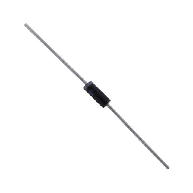


 工商网监
湘ICP备2023018690号
工商网监
湘ICP备2023018690号
