Miniature Rocker Switch
A8L
Miniature Rocker Switch for High
Capacity Switching
• Withstands inrush currents up to 100 A with a
unique switching mechanism.
• Soft touch with firm switching action.
• Easy to mount by snap fitting.
• Contact gap of 3 mm minimum.
• UL and cUL standards approved. Conforms to EN
standards.
RoHS Compliant
Caution
Refer to Precautions
■
List of Models
SPST
Contact Form
Terminals
Color of caps and cases
Without markings
OFF
ON
Marking
on caps
2
1
Solder terminals
Right-angled
PCB terminals
PCB terminals
Left-angled
PCB terminals
Quick-connect
terminals #187
Black
Black
Black
Black
Black
A8L-11-11N1
A8L-11-12N1
A8L-11-13N1
A8L-11-14N1
A8L-11-15N1
A8L-11-11N2
A8L-11-12N2
A8L-11-13N2
A8L-11-14N2
A8L-11-15N2
A8L-11-11N3
A8L-11-12N3
A8L-11-13N3
A8L-11-14N3
A8L-11-15N3
A8L-11-11N6
A8L-11-12N6
A8L-11-13N6
A8L-11-14N6
A8L-11-15N6
Left-angled
PCB terminals
Quick-connect
terminals #187
Quantity
per box
300
DPST
Contact Form
Terminals
Color of caps and cases
Without markings
OFF
ON
Marking
on caps
2
4
1
3
Solder terminals
PCB terminals
Right-angled
PCB terminals
Black
Black
Black
Black
Black
A8L-21-11N1
A8L-21-12N1
A8L-21-13N1
A8L-21-14N1
A8L-21-15N1
A8L-21-11N2
A8L-21-12N2
A8L-21-13N2
A8L-21-14N2
A8L-21-15N2
A8L-21-11N3
A8L-21-12N3
A8L-21-13N3
A8L-21-14N3
A8L-21-15N3
A8L-21-11N6
A8L-21-12N6
A8L-21-13N6
A8L-21-14N6
A8L-21-15N6
Quantity
per box
300
1
�A8L
■
A8L
Ratings
Non-inductive
Rated load
Inductive
Resistive load
Lamp load
Inductive load
Inductive motor load
125 VAC
10 A
10 A
8A
8A
250 VAC
10 A
10 A
8A
8A
Note:
1. The non-inductive lamp load has an inrush current 10 times steady current.
2. The inductive load has a power factor of 0.4 minimum (AC).
3. The motor load has an inrush current 6 times steady current.
The above ratings were tested under the following conditions:
1. Ambient temperature:20±2°C
2. Ambient humidity:65±5%RH
3. Switching frequency:7 times/min
■
Approved Safety Standards
UL, cUL (UL1054/CSA C22.2 No. 55)
10 A, 125 VAC; 10 A, 250 VAC
TÜV (EN61058-1)
10 (8) A, 250 VAC
■
Characteristics
Permissible operating
frequency
Insulation resistance
Dielectric strength
Vibration resistance
Shock resistance
Durability
Mechanical
Electrical
20 operations/min max.
7 operations/min max.
100 MΩ min. (500 VDC)
Between terminals
of the same polarity
Between terminals
of the different
polarity
Between charged
metal parts and the
ground terminal
Malfunction
Malfunction
Destruction
Mechanical
Electrical
2,000 VAC, 50/60 Hz, for 1 min
2,000 VAC, 50/60 Hz, for 1 min
4,000 VAC, 50/60 Hz, for 1 min
10 to 55 Hz, 1.5-mm double amplitude
300 m/s2
500 m/s2
50,000 operations min.
10,000 operations min.
100 A max. (8.3 ms max.)
–20 to +55°C (with no icing or condensation)
45 to 85%RH
Inrush current
Ambient operating temperature
Ambient operating humidity
Note:
■
Consult your OMRON representative for details of performance characteristics with respect to individual standards.
Dimensions
Note:
(Unit: mm)
The following illustrations and drawings are for 2 poles (DPST) models, 1 pole (SPST) models have single side terminals.
Solder Terminals
A8L-11-11N1
A8L-11-11N2
A8L-11-11N3
A8L-11-11N6
■
A8L-21-11N1
A8L-21-11N2
A8L-21-11N3
A8L-21-11N6
21
Operating Characteristics
No. of poles
Operating force(OF)
15
10.8
5.6 2
16.5
13
2 dia.
3.6
8.5
1.4 dia.
4.8
2.3
10
19
Note:
2
0.8
8.75
12.5
Unless otherwise specified, a tolerance of ±0.4 mm applies to all dimensions.
1 (SPST)
2 (DPST)
2.16±1.18 N
3.92±2.45 N
{220±120 gf}
{400±250 gf}
�A8L
A8L
PCB Terminals
A8L-11-12N1
A8L-11-12N2
A8L-11-12N3
A8L-11-12N6
■
21
A8L-21-12N1
A8L-21-12N2
A8L-21-12N3
A8L-21-12N6
Operating Characteristics
No. of poles
Operating force(OF)
15
1 (SPST)
2 (DPST)
2.16±1.18 N
3.92±2.45 N
{220±120 gf}
{400±250 gf}
10.8
5.6 2
16.5
13
4
0.8
1.3
8.75
12.5
10
19
PCB Dimensions
(Bottom View)
Four, 1.8±0.1-dia. holes
8.75±0.1
10±0.1
Right-angled PCB Terminals
A8L-11-13N1
A8L-11-13N2
A8L-11-13N3
A8L-11-13N6
A8L-21-13N1
A8L-21-13N2
A8L-21-13N3
A8L-21-13N6
■
21
Operating Characteristics
No. of poles
Operating force(OF)
15
1 (SPST)
2 (DPST)
2.16±1.18 N
3.92±2.45 N
{220±120 gf}
{400±250 gf}
10.8
5.6 2
16.5
13
2
0.8
PCB Dimensions
(Bottom View)
3.3
12.5
10
19
Four, 1.8±0.1-dia. holes
8
4
8±0.1
10±0.1
Left-angled PCB Terminals
A8L-11-14N1
A8L-11-14N2
A8L-11-14N3
A8L-11-14N6
A8L-21-14N1
A8L-21-14N2
A8L-21-14N3
A8L-21-14N6
■
21
Operating Characteristics
No. of poles
Operating force(OF)
15
1 (SPST)
2 (DPST)
2.16±1.18 N
3.92±2.45 N
{220±120 gf}
{400±250 gf}
10.8
5.6 2
16.5
13
2
8
PCB Dimensions
(Bottom View)
Four, 1.8±0.1-dia. holes
3.3
10
19
0.8
4
12.5
8±0.1
10±0.1
Note:
Unless otherwise specified, a tolerance of ±0.4 mm applies to all dimensions.
3
�A8L
A8L
Quick-connect Terminals #187
A8L-11-15N1
A8L-11-15N2
A8L-11-15N3
A8L-11-15N6
A8L-21-15N1
A8L-21-15N2
A8L-21-15N3
A8L-21-15N6
■
21
Operating Characteristics
No. of poles
Operating force(OF)
15
1 (SPST)
2 (DPST)
2.16±1.18 N
3.92±2.45 N
{220±120 gf}
{400±250 gf}
10.8
5.6 2
16.5
13
1.4±0.1 dia.
hole
8.5
4.8
3±0.1
0.8
10
19
Note:
■
8.75
12.5
Unless otherwise specified, a tolerance of ±0.4 mm applies to all dimensions.
Panel Cutout
Panel Cutout for Angled PCB Terminals
X
(A8L-@@-@3@@, A8L-@@-@4@@)
Y
X
Panel thickness (mm)
0.75 to 1.25
1.26 to 2.5
Note:
X (mm)
Y (mm)
19.2
0
−0.1
12.9
19.4
+0.1
−0.3
12.9 +0.1
0
12.9+0.1
0
17.5±0.3
+0.1
0
Recommended panel material: SPCC
Play R
15±0.3
Panel thickness (mm)
X (mm)
0.75 to 1.25
0
19.2 −0.1
1.26 to 2.5
+0.1
19.4 −0.3
Edge
When processing the panel, be sure that the Play R is on the
switch operation side.
Be sure that the Edge is on the reverse side of panel when
processing.
■ Precautions
Be sure to read the Safety precautions common to all Rocker Switches for correct use.
4
�A8L
A8L
• Application examples provided in this document are for reference only. In actual applications, confirm equipment functions and safety before using the product.
• Consult your OMRON representative before using the product under conditions which are not described in the manual or applying the product to nuclear control systems, railroad
systems, aviation systems, vehicles, combustion systems, medical equipment, amusement machines, safety equipment, and other systems or equipment that may have a serious
influence on lives and property if used improperly. Make sure that the ratings and performance characteristics of the product provide a margin of safety for the system or
equipment, and be sure to provide the system or equipment with double safety mechanisms.
Note: Do not use this document to operate the Unit.
OMRON Corporation
ELECTRONIC AND MECHANICAL COMPONENTS COMPANY
Contact: www.omron.com/ecb
Cat. No. A114-E1-06
1212(0207)(O)
�
很抱歉,暂时无法提供与“A8L-11-15N1”相匹配的价格&库存,您可以联系我们找货
免费人工找货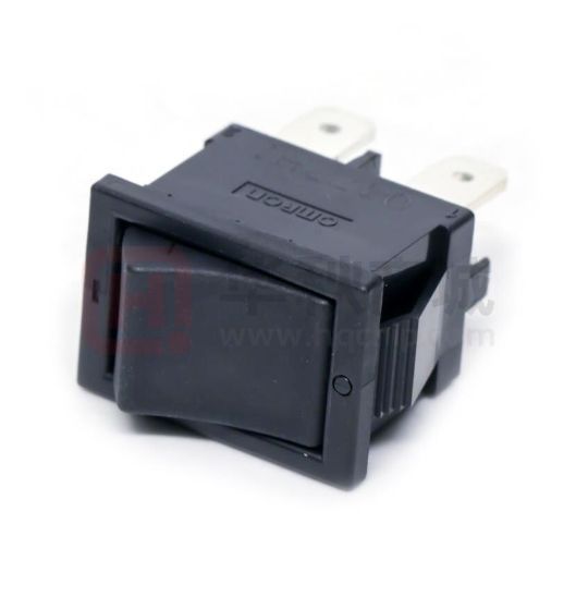


 工商网监
湘ICP备2023018690号
工商网监
湘ICP备2023018690号
