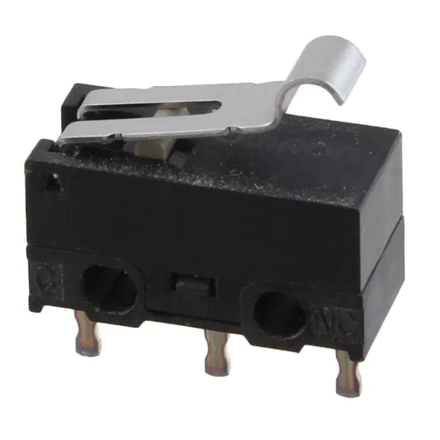
D2F
Ultra Subminiature Basic Switch
Ultra Subminiature Basic
Switch with plenty of
terminal variations
● Incorporating a snapping mechanism made with
two highly precise split springs that ensures long
D
2
F
durability.
● Using insertion molded terminals
that prevents flux penetration.
● In addition to self-clinching PCB, left-angled,
right-angled terminals,
2 types of soldering terminals are available.
● Lineup of 5A type for high load applications.
RoHS Compliant
Model Number Legend
1 @
2 @
3 @
4
D2F - @
1. Ratings
None : 125 VAC 3A
125 VAC 1A (Low operating force)
01 : 30 VDC 0.1A
5 : 250 VAC 5A
2. Maximum Operating Force (OF)
None : 1.47 N {150 gf}
F : 0.74 N {75 gf}
4. Terminals
None : PCB terminals (Straight)
-T : Self-clinching PCB terminals
-A : PCB terminals (Right-angled)
-A1 : PCB terminals (Left-angled)
-D3 : Solder terminals
-D : Compact solder terminals
Note. The given values are for pin plunger models only.
3. Actuator
None : Pin plunger
L
L2
L3
L30
: Hinge lever
: Hinge Roller Lever
: Simulated roller lever (R1.3)
: Simulated roller lever (R2.5)
1
�D2F
Ultra Subminiature Basic Switch
List of Models
Ratings
Maximum Operating Force (OF) *
Actuator
Terminals
Pin plunger
D
2
F
Hinge lever
Hinge roller
lever
Simulated roller
lever (R1.3)
Simulated roller
lever (R2.5)
*
3A
1A
General Purpose
1.47 N {150 gf}
Low Operating Force
0.74 N {75 gf}
0.1 A
General Purpose
1.47 N {150 gf}
5A
Low Operating Force
0.74 N {75 gf}
PCB terminals (Standard)
D2F
D2F-F
D2F-01
D2F-01F
Self-clinching PCB terminals
D2F-T
D2F-F-T
D2F-01-T
D2F-01F-T
PCB terminals (Right-angled)
D2F-A
D2F-F-A
D2F-01-A
D2F-01F-A
PCB terminals (Left-angled)
D2F-A1
D2F-F-A1
D2F-01-A1
D2F-01F-A1
Solder terminals
D2F-D3
D2F-F-D3
D2F-01-D3
D2F-01F-D3
Compact solder terminals
D2F-D
D2F-F-D
D2F-01-D
D2F-01F-D
PCB terminals (Standard)
D2F-L
D2F-FL
D2F-01L
D2F-01FL
Self-clinching PCB terminals
D2F-L-T
D2F-FL-T
D2F-01L-T
D2F-01FL-T
PCB terminals (Right-angled)
D2F-L-A
D2F-FL-A
D2F-01L-A
D2F-01FL-A
PCB terminals (Left-angled)
D2F-L-A1
D2F-FL-A1
D2F-01L-A1
D2F-01FL-A1
Solder terminals
D2F-L-D3
D2F-FL-D3
D2F-01L-D3
D2F-01FL-D3
Compact solder terminals
D2F-L-D
D2F-FL-D
D2F-01L-D
D2F-01FL-D
PCB terminals (Standard)
D2F-L2
D2F-FL2
D2F-01L2
D2F-01FL2
Self-clinching PCB terminals
D2F-L2-T
D2F-FL2-T
D2F-01L2-T
D2F-01FL2-T
PCB terminals (Right-angled)
D2F-L2-A
D2F-FL2-A
D2F-01L2-A
D2F-01FL2-A
PCB terminals (Left-angled)
D2F-L2-A1
D2F-FL2-A1
D2F-01L2-A1
D2F-01FL2-A1
Solder terminals
D2F-L2-D3
D2F-FL2-D3
D2F-01L2-D3
D2F-01FL2-D3
Compact solder terminals
D2F-L2-D
D2F-FL2-D
D2F-01L2-D
D2F-01FL2-D
PCB terminals (Standard)
D2F-L3
D2F-FL3
D2F-01L3
D2F-01FL3
Self-clinching PCB terminals
D2F-L3-T
D2F-FL3-T
D2F-01L3-T
D2F-01FL3-T
PCB terminals (Right-angled)
D2F-L3-A
D2F-FL3-A
D2F-01L3-A
D2F-01FL3-A
PCB terminals (Left-angled)
D2F-L3-A1
D2F-FL3-A1
D2F-01L3-A1
D2F-01FL3-A1
Solder terminals
D2F-L3-D3
D2F-FL3-D3
D2F-01L3-D3
D2F-01FL3-D3
Compact solder terminals
D2F-L3-D
D2F-FL3-D
D2F-01L3-D
D2F-01FL3-D
PCB terminals (Standard)
D2F-L30
D2F-FL30
D2F-01L30
D2F-01FL30
Self-clinching PCB terminals
D2F-L30-T
D2F-FL30-T
D2F-01L30-T
D2F-01FL30-T
PCB terminals (Right-angled)
D2F-L30-A
D2F-FL30-A
D2F-01L30-A
D2F-01FL30-A
PCB terminals (Left-angled)
D2F-L30-A1
D2F-FL30-A1
D2F-01L30-A1
D2F-01FL30-A1
Solder terminals
D2F-L30-D3
D2F-FL30-D3
D2F-01L30-D3
D2F-01FL30-D3
Compact solder terminals
D2F-L30-D
D2F-FL30-D
D2F-01L30-D
D2F-01FL30-D
General Purpose
1.47 N {150 gf}
D2F-5
-
D2F-5L
-
-
D2F-5L3
-
-
OF are value for Pin plunger.
Contact Form
Contact Specifications
●SPDT
Item
Model
D2F models
D2F-5 models
Specifications
Contact
Material
Minimum applicable load (see note) *
NO NC
*
Crossbar
Silver alloy
Gap (standard value)
COM
D2F-01 models
Gold alloy
0.25 mm
100 mA at 5 VDC
1 mA at 5 VDC
Please refer to "Using Micro Loads" in "Precautions" for more information
on the minimum applicable load.
Ratings
Model
D2F models
D2F-01 models
D2F-5 models
Maximum Operating 1.47N (General-purpose) 0.74N (Low Operating Force) 1.47N (General-purpose) 0.74N (Low Operating Force) 1.47N (General-purpose)
Force (OF)
Resistive load
Rated voltage
125 VAC
3A
1A
-
30 VDC
2A
0.5 A
0.1 A
-
-
5A
250 VAC
-
Note. The above rating values apply under the following test conditions.
(1) Ambient temperature: 20±2°C
(2) Ambient humidity: 65±5%
(3) Operating frequency: 30 operations/min
Approved Safety Standard
The items shown in the "List of Models" above are not standard approved models.
Consult your OMRON sales representative for specific models with standard approvals.
UL (UL1054) /CSA (CSA C22.2 No.55)
Rated voltage
2
D2F (General-purpose)
D2F (Low operating force)
125 VAC
Model
3A
1A
D2F-01
-
30 VDC
2A
0.5 A
0.1 A
-
�D2F
Ultra Subminiature Basic Switch
Characteristics
Model
Item
D2F models
D2F-01 models
Pin plunger models: 1 mm to 500 mm/s,
Lever models: 5 mm to 500 mm/s
Permissible operating speed
Pin plunger models: 200 operations/min,
Lever models: 100 operations/min
Mechanical
Permissible operating
frequency
D2F-5 models
0.74 N (Low operating force) 1.47 N (General-purpose) 1.47 N (General-purpose)
Electrical
30 operations/min
Insulation resistance
100 MΩ min. (at 500 VDC with insulation tester)
Contact resistance (initial value)
Dielectric strength
Vibration resistance * 1
100 mΩ max.
50 mΩ max.
600 VAC 50/60 Hz for 1min
Between current-carrying metal
parts and ground
1,500 VAC 50/60 Hz for 1min
Between each terminal and
non-current-carrying metal parts
1,500 VAC 50/60 Hz for 1min
Malfunction
1,000 m/s2 {approx. 100G} max.
300 m/s2 {approx. 30G} max.
Malfunction * 1
Mechanical
Durability * 2
D
2
F
10 to 55 Hz, 1.5-mm double amplitude
Durability
Shock resistance
30 mΩ max.
Between terminals of the same
polarity
1,000,000 operations min. (60 operations/min)
100,000 operations
min.
(30 operations/min)
Electrical
30,000 operations min.
(30 operations/min)
Degree of protection
10,000 operations min.
(30 operations/min)
IEC IP40
-40°C to +85°C (at ambient humidity 60% max.)
(with no icing or condensation)
Ambient operating temperature
Ambient operating humidity
85% max. (for +5°C to +35°C)
Weight
Approx. 0.5 g (pin plunger models)
Note. The data given above are initial values.
*1. The values are at Free Position and Total Travel Position values for pin plunger, and Total Travel Position value for lever.
Close or open circuit of the contact is 1ms max.
*2. For testing conditions, consult your OMRON sales representative.
Terminals/Appearances
(Unit: mm)
●PCB terminals (Straight)
●Self-clinching PCB terminals
5.8±0.15
3-1.2 dia. holes
3.15
6.5±0.1
5.08
5.08
12.8±0.15
1.5
1.5
3.5
3.4
3.15
0.4
0.9
6.5±0.1
5.08
5.08
12.8±0.15
5.8±0.15
●PCB terminals (Right-angled)
5.08±0.1
12.8±0.15
1.6±0.15
1.5
0.9 0.4±0.05
1.25±0.15
5.8±0.15
●PCB terminals (Left-angled)
1.5
1.5
2.6±0.2
3.15
6.5±0.1
5.8±0.15
0.9
3.1±0.2
5.08
5.08
12.8±0.15
●Solder terminals
2.6±0.2
3.15
0.4
1.5
1.5
3.5
3.15
6.5±0.1
5.08
0.9
0.4
5.8±0.15
3.1±0.2
●Compact solder terminals
2
0.5
6.5±0.1
5.08
5.08
12.8±0.15
3.15
1.2
2.2
0.4
5.8±0.15
5.08
3−0.8 dia. holes
6.5±0.1
5.08
5.08
1.6
2.4
0.4
5.8±0.15
12.8±0.15
12.8±0.15
Mounting Holes (Unit: mm)
2-2 dia. mounting holes
6.5±0.15
3
�D2F
Ultra Subminiature Basic Switch
Dimensions (Unit: mm) /Operating Characteristics
The following illustrations and drawings are for D2F models with PCB terminals (straight). Self-clinching, solder, compact solder, and right-angled, left angled terminals
are omitted from the following drawings. Refer to the previous page for these terminals.
When ordering, replace @ with the code for the terminal that you need. See the "List of Models" for available combinations of models.
D
2
F
●Pin Plunger Models
D2F-@
D2F-01@
D2F-F@
D2F-01F@
D2F-5
1.2
12.7
dia.
2.2+0.12
0
2+0.12
dia. holes
0
A
5.7
2.9
PT
5.2
5
Operating
Characteristics
Operating Force
Releasing Force
OP
2+0.12
0
Model
Operating Position
D2F-F@
D2F-01F@
OF Max. 1.47 N {150 gf} 0.74 N {75 gf}
RF Min. 0.20 N {20 gf} 0.05 N {5 gf}
Pretravel
PT Max.
Overtravel
OT Min.
Movement Differential MD Max.
0.4
D2F-@
D2F-01@
D2F-5
OP
0.5 mm
0.25 mm
0.12 mm
0.5 mm
0.25 mm
0.12 mm
5.5±0.3 mm
5.8±0.15
●Hinge Lever Models
D2F-L@
D2F-01L@
D2F-FL@
D2F-01FL@
D2F-5L
12.8
(10.8)
Operating
Characteristics
A
t=0.3 *
3
Operating Force
Releasing Force
FP
Model
OF Max.
RF Min.
Overtravel
OT Min.
Movement Differential MD Max.
OP
Free Position
Operating Position
FP Max.
OP
D2F-L@
D2F-01L@
D2F-5L
D2F-FL@
D2F-01FL@
0.78 N {80 gf}
0.05 N {5 gf}
0.25 N {25 gf}
0.02 N {2 gf}
0.55 mm
0.5 mm
0.55 mm
0.5 mm
10 mm
6.8±1.5 mm
* Stainless-steel lever
●Simulated Roller Lever Models (R1.3)
D2F-L3@
12.7
D2F-01L3@
(7.5)
D2F-FL3@
10
D2F-01FL3@
R1.3
D2F-5L3
Operating
Characteristics
A
t=0.3 *
2.1
3
Operating Force
Releasing Force
Model D2F-L3@
D2F-01L3@
D2F-5L3
OF Max.
RF Min.
Overtravel
OT Min.
Movement Differential MD Max.
FP
OP
Free Position
Operating Position
FP Max.
OP
D2F-FL3@
D2F-01FL3@
0.78 N {80 gf}
0.05 N {5 gf}
0.39 N {40 gf}
0.02 N {2 gf}
0.5 mm
0.45 mm
0.5 mm
0.45 mm
13 mm
8.5±1.2 mm
* Stainless-steel lever
●Simulated Roller Lever Models (R2.5)
D2F-L30@
D2F-01L30@
12.7
D2F-FL30@
D2F-01FL30@
3.3
t=0.3 *
R2.5 A
3
OP
FP
Operating
Characteristics
Operating Force
Releasing Force
Note 1. Unless otherwise specified, a tolerance of ±0.4 mm applies to all dimensions.
Note 2. The operating characteristics are for operation in the A direction ( ).
4
OF Max.
RF Min.
Overtravel
OT Min.
Movement Differential MD Max.
Free Position
Operating Position
* Stainless-steel lever
Model D2F-L30@
D2F-01L30@
FP Max.
OP
D2F-FL30@
D2F-01FL30@
0.54 N {55 gf}
0.04 N {4 gf}
0.3 N {31 gf}
0.02 N {2 gf}
0.5 mm
0.5 mm
0.5 mm
0.5 mm
12.6 mm
9.5±1.0 mm
�D2F
Ultra Subminiature Basic Switch
●Hinge Roller Lever Models
D2F-L2@
D2F-01L2@
D2F-FL2@
D2F-01FL2@
12.8
4
(10)
A
4.8 dia.×2.8 *2
(4.6)
Operating Force
Releasing Force
OF Max.
RF Min.
Overtravel
OT Min.
Movement Differential MD Max.
t=0.3 *1
4
Model D2F-L2@
D2F-01L2@
Operating
Characteristics
FP
Free Position
Operating Position
OP
D2F-FL2@
D2F-01FL2@
0.78 N {80 gf}
0.05 N {5 gf}
0.39 N {40 gf}
0.02 N {2 gf}
0.55 mm
0.5 mm
0.55 mm
0.5 mm
FP Max.
OP
16.5 mm
13±2 mm
D
2
F
*1. Stainless-steel lever
*2. Polyacetal resin roller
Note 1. Unless otherwise specified, a tolerance of ±0.4 mm applies to all dimensions.
Note 2. The operating characteristics are for operation in the A direction ( ).
Precautions
★Please refer to "Basic Switches Common Precautions" for correct use.
Cautions
• Terminal connection
When soldering, make sure that the temperature of the
soldering iron tip is not higher than 300°C, and complete the
soldering within 3 seconds. Do not apply any external force for
1 minute after soldering. Soldering at an excessively high
temperature or soldering for more than 3 seconds may
deteriorate the characteristics of the Switch.
• Connecting to PCB terminal Boards
When using automatic soldering baths, we recommend
soldering at 260°C ±5°C within 5 seconds. Make sure that the
liquid surface of the solder does not flow over the edge of the
board.
When soldering terminals manually, perform soldering within 3
seconds at iron tip temperature not higher than 350°C. Do not
apply any external force for at least 1 minute after soldering.
When applying solder, keep the solder away from the case of
the Switch and do not allow solder or flux to flow into the case.
●Mounting
Use M2 mounting screws with plane washers or spring washers
to securely mount the Switch. Tighten the screws to a torque of
0.08 to 0.1 N·m {0.8 to 1 kgf·cm}.
●Using Micro Loads
Using a model for ordinary loads to open or close the contact of
a micro load circuit may result in faulty contact. Use models that
operate in the following range. However, even when using micro
load models within the following operating range, if inrush
current occurs when the contact is opened or closed, it may
increase the contact wear and so decrease durability. Therefore,
insert a contact protection circuit where necessary. The
minimum applicable load is the N-level reference value. This
value indicates the malfunction reference level for the reliability
level of 60% (λ60).
(JIS C5003)
The equation, λ60=0.5×10⁻⁶/operation, indicates that the
1
estimated malfunction rate is less than
operations
2,000,000
with a reliability level of 60%.
Voltage (V)
●Soldering
Correct Use
30
16.6 mA 100 mA
0.16 mA
24
Operating range
for micro load
models
D2F-01
Operating
range for
general-load
models
D2F
12
5
1 mA
0
0.1
1
10
100
1,000
Current (mA)
5
�D2F
Ultra Subminiature Basic Switch
D
2
F
• Application examples provided in this document are for reference only. In actual applications, confirm equipment functions and safety before using the product.
• Consult your OMRON representative before using the product under conditions which are not described in the manual or applying the product to nuclear control systems, railroad
systems, aviation systems, vehicles, combustion systems, medical equipment, amusement machines, safety equipment, and other systems or equipment that may have a serious
influence on lives and property if used improperly. Make sure that the ratings and performance characteristics of the product provide a margin of safety for the system or
equipment, and be sure to provide the system or equipment with double safety mechanisms.
Note: Do not use this document to operate the Unit.
OMRON Corporation
Electronic and Mechanical Components Company
6
Contact: www.omron.com/ecb
Cat. No. B036-E1-12
0318(0207)(O)
�


 工商网监
湘ICP备2023018690号
工商网监
湘ICP备2023018690号

