E2C
E2C
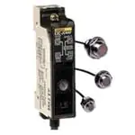
Miniature Inductive Prox
E2C
Cylindrical Inductive Sensors
with Separate Amplifiers Provide
Variable Detecting Capabilities
■ Separate amplifier allows sensor to fit in
space-confined sites, providing easy
access for monitoring and remote
adjustments
■ Detecting distance and differential travel
can be adjusted to meet specific
application requirements
■ Adjustable differential travel to set
switching trigger point available on
some amplifiers
Ordering Information
■ SENSORS
Miniature Sizes
Sensor type
Size
Nominal detecting distance
Part number
Shielded
2.0 mm dia.
0.5 mm (0.02 in)
E2C-CR5B
3.5 mm dia.
0.8 mm (0.03 in)
E2C-CR8A
3.8 mm dia.
0.8 mm (0.03 in)
E2C-CR8B
M5
1 mm (0.04 in)
E2C-X1A
5.4 mm dia.
1 mm (0.04 in)
E2C-C1A
Shielded
M8
1.5 mm (0.06 in)
E2C-X1R5A
M12
2 mm (0.08 in)
E2C-X2A
M18
5 mm (0.20 in)
E2C-X5A
M30
10 mm (0.39 in)
E2C-X10A
Unshielded
40 mm dia.
20 mm (0.79 in)
E2C-C20MA
Standard Sizes
Sensor type
Size
Nominal detecting distance
Part number
■ AMPLIFIERS
Socket-Mount Types
Size
Applicable
sensors
Supply
voltage
Output type
Part number
1/16 DIN
All models
90 to 264 VAC,
50/60 Hz
Transistor
and relay
E2C-AK4A
10 to 30 VDC
Open collector
NPN and PNP
E2C-AM4A
Miniature
E2C-CR8A, E2C-CR8B, E2C-X1A,
E2C-C1A, E2C-X1R5A
10 to 30 VDC
E2C-CR5B
NPN
PNP
NPN
PNP
E2C-GE4A
E2C-GF4A
E2C-GE4B
E2C-GF4B
2
�E2C
E2C
■ AMPLIFIERS
Track-Mount Types
Size
Applicable sensors
Prewired
E2C-CR8A, E2C-X1A, E2C-C1A
E2C-X1R5A, E2C-X2A
10 to 30 VDC,
NPN with alarm output
E2C-JC4AP
Supply voltage
Output type
Part number
Screw terminal
E2C-CR8A, E2C-X1A,
E2C-C1A, E2C-X1R5A
Open collector NPN and PNP
E2C-WH4AF
■ ACCESSORIES
Description
Mounting brackets
for sensors
Sockets for
amplifiers
E2C-AK4A
amplifier
E2C-AM4A
amplifier
E2C-G❑4❑
amplifiers
Panel mounting adapters
for E2C-A❑4A amplifiers
Protective covers
for E2C-A❑4A amplifiers
Mounting track
Fits 3.5 mm and 3.8 mm dia. unthreaded sensor
Fits M8 size threaded sensor
Fits M12 size threaded sensor
Fits M18 size threaded sensor
Fits M30 size threaded sensor
Bottom surface or track mounting, top screw terminals
Panel mounting, bottom solder terminal
Back mounting, for use with Y92F-30 mounting adapter, bottom screw terminals
Bottom surface or track mounting, top screw terminals
Panel mounting, bottom solder terminals
Back mounting, for use with Y92F-30 mounting adapter, bottom screw terminals
Bottom surface or track mounting, top screw terminals
Panel mounting, bottom solder terminals
Bottom surface mounting, bottom screw terminals
Fits behind panel; ideal for side by side installation.
Use P2CF-❑❑ sockets.
Installs through panel front; amplifier face fits bezel, rear of amplifier clips
to adapter. Use P3G-❑❑ sockets. Charcoal gray.
Hard plastic cover; not for use with Y92F-70 panel adapter
Soft plastic cover; not for use with Y92F-70 panel adapter
DIN rail, 50 cm (1.64 ft) length
DIN rail, 1 m (3.28 ft) length
End plate
Spacer
Part number
Y92E-F3R5
Y92E-B8
Y92E-B12
Y92E-B18
Y92E-B30
P2CF-11
PL11
P3G-11
P2CF-08
PL08
P3G-08
PYF08A-E
PY08
PYF08M
Y92F-30
Y92F-70
Y92A-48
Y92A-48D
PFP-50N
PFP-100N
PFP-M
PFP-S
■ REPLACEMENT PARTS
Description
Mounting hardware
includes one
pair of metal
nuts and washers
Fits M5 size sensors (supplied with each sensor)
Fits M8 size sensors (supplied with each sensor)
Fits M12 size sensors (supplied with each sensor)
Fits M18 size sensors (supplied with each sensor)
Fits M30 size sensors (supplied with each sensor)
3
Part number
M5-MHWS
M8-MHWS
M12-MHWS
M18-MHWS
M30-MHWS
�E2C
E2C
Specifications
■ MINIATURE SENSORS
Part number
Sensor type
Body
E2C-CR5B
E2C-CR8A
E2C-CR8B
E2C-X1A
Inductive
Size
2.0 mm dia.
3.5 mm dia.
3.8 mm dia.
M5
Type
Shielded
Required amplifier
E2C-AK4A,
E2C-AK4A, E2C-AM4A, E2C-GE4A,
E2C-AM4A,
E2C-GF4A, E2C-JC4AP or E2C-WH4AF
E2C-GE4B or
E2C-GF4B
Detectable object type
Metallic objects
Usable setting distance at
0 to 0.5 mm
0 to 0.8 mm
0 to 1.0 mm
ambient (with standard target)
(0 to 0.02 in)
(0 to 0.03 in)
(0 to 0.04 in)
Usable setting distance at
0 to 0.7 mm
0 to 1.2 mm
0 to 1.5 mm
0° to 40°C (with standard target) (0 to 0.028 in)
(0 to 0.047 in)
(0 to 0.059 in)
Standard target size
5 x 5 x 1 mm
(mild steel, L x W x H)
(0.20 x 0.20 x 0.04 in)
Differential travel
See "Differential Travel" tables
Response frequency
1 kHz
Materials
Housing
304 stainless steel
Sensing face ABS
Cable sheath Polyethylene
Mounting
—
Optional mounting strap
Two lock washers
Y92E-F3R5, order separately
and M5 nuts included
Connections
Prewired
Two-conductor cable, 3 m (9.8 ft) length
Weight with cable
10 g (0.4 oz.)
40 g (1.4 oz.)
45 g (1.6 oz.)
Enclosure
UL
—
ratings
NEMA
1,2
1, 3, 4, 6, 12, 13
IEC 144
IP64
IP67
Approvals
UL
—
CSA
—
Ambient operating temperature -25° to 70°C (-13° to 158°F)
Vibration
10 to 55 Hz, 1.5 mm (0.06 in) double amplitude, 2 hours each, X and Y directions
Shock
50 G's, 3 times each, X and Y directions
4
E2C-C1A
5.4 mm dia.
Nickel-plated brass
—
�E2C
E2C
■ STANDARD SIZE SENSORS
Part number
Sensor type
Body
E2C-X1R5A
E2C-X2A
E2C-X5A
E2C-X10A
Inductive
Size
M8
M12
M18
M30
Type
Shielded
Required amplifier
E2C-JC4AP, E2C-AK4A or E2C-AM4A
E2C-AK4A or E2C-AM4A
Detectable object type
Metallic objects
Usable setting distance at
0 to 1.5 mm
0 to 2 mm
0 to 5 mm
0 to 10 mm
ambient (with standard target) (0 to 0.06 in)
(0 to 0.08 in)
(0 to 0.20 in)
(0 to 0.39 in)
Usable setting distance
0 to 2 mm
0 to 2.5 mm
0 to 7 mm
0 to 15 mm
0° to 40°C (with standard target) (0 to 0.079 in)
(0 to 0.098 in)
(0 to 0.276 in)
(0 to 0.591 in)
Standard target size
8 x 8 x 1 mm
12 x 12 x 1 mm
18 x 18 x 1 mm
30 x 30 x 1 mm
(mild steel, L x W x H)
(0.32 x 0.32
(0.47 x 0.47
(0.71 x 0.71
(1.18 x 1.18
x 0.04 in)
x 0.04 in)
x 0.04 in)
x 0.04 in)
Differential travel
See "Differential Travel" tables
Response frequency
800 Hz
350 Hz
100 Hz
Materials
Housing
Nickel-plated brass
Sensing face ABS
Cable sheath Polyethylene
Mounting
Two lock washers Two lock washers
Two lock washers
Two lock washers
and M8 nuts
and M12 nuts
and M18 nuts
and M30 nuts
included. Bracket included. Bracket
included. Bracket
included. Bracket
Y92E-B8 optional. Y92E-B12 optional. Y92E-B18 optional. Y92E-B30 optional.
Connections
Prewired
Two-conductor cable, 3 m (9.8 ft) length
Weight with cable
50 g (1.8 oz.)
60 g (2.1 oz.)
140 g (4.9 oz.)
270 g (9.5 oz.)
UL
—
Enclosure
ratings
NEMA
1, 3, 4, 6, 12, 13
IEC 144
IP67
Approvals
UL
—
CSA
—
Ambient operating temperature -25° to 70°C (-13° to 158°F)
Vibration
10 to 55 Hz, 1.5 mm (0.06 in) double amplitude, 2 hours each, X and Y directions
Shock
50 G's, 3 times each, X and Y directions
5
E2C-C20MA
40 mm dia.
Unshielded
0 to 20 mm
(0 to 0.79 in)
0 to 28 mm
(0 to 1.102 in)
50 x 50 x 1 mm
(1.97 x 1.97
x 0.04 in)
50 Hz
—
300 g (10.6 oz.)
�E2C
E2C
■ AMPLIFIERS
Socket-Mount Type
Part number
Supply voltage
Current consumption
Differential travel
Control Relay Type
output
Max. load
DC
solidstate
Min. load
Type
Max. load
Max. on-state
voltage drop
Indicators
Materials
Mounting
Case
Connections
Weight (not including socket)
Enclosure
UL
ratings
NEMA
IEC 144
Approvals
UL
CSA
Ambient operating temperature
Vibration
Shock
E2C-AK4A
E2C-AM4A
90 to 264 VAC, 10 to 30 VDC
50/60 Hz
55 mA max.
25 mA max.
See "Differential Travel" tables
SPDT
—
2 A, 250 VAC
—
(p.f. = 1)
1 mA, 5 VDC
—
Transistor,
One NPN open
SPST
collector, one
PNP open
collector
50 mA, 40 VDC 200 mA
2 VDC
1.5 VDC
E2C-GE4A
E2C-GF4A
E2C-GE4B
E2C-GF4B
NPN open
collector with
pull-up
PNP open
collector with
pull-down
NPN open
collector with
pull-up
PNP open
collector with
pull-down
100 mA
Output Operation (red LED) and
Output Operation (red LED)
Output Stability (red LED)
Plastic
Requires
Requires
Requires PYF08A-E, PY08 or PYF08M socket
P2CF-11,
P2CF-08,
(not included). Order separately from Accessories.
PL11 or P3G-11 PL08 or P3G-08
socket (not
socket (not
included). Order included). Order
separately from separately from
Accessories.
Accessories.
Plated steel screw terminals or solder terminals, refer to sockets in Accessories section.
250 g (8.8 oz.)
140 g (4.9 oz.) 20 g (0.7 oz.)
—
1
IP 40
—
—
-10° to 55°C (14° to 131°F)
10 to 25 Hz, 2 mm (0.08 in) double amplitude, 2 hours each, X and Y directions
10 G's, 3 times each, X and Y directions
6
�E2C
E2C
■ AMPLIFIERS
Track-Mount Type
Part number
Supply voltage
Current consumption
Differential travel
Control DC
Type
output solid- Max. load
state
Max. on-state
voltage drop
Alarm output
Type
Max. load
Indicators
Materials
Mounting
Case
Connections
Weight
Enclosure
ratings
UL
NEMA
IEC 144
Approvals
UL
CSA
Ambient operating temperature
Vibration
Shock
E2C-JC4AP
10 to 30 VDC
45 mA
See "Differential Travel" tables
NPN open collector
100 mA
1 VDC
E2C-WH4AF
25 mA
One NPN open collector, one PNP open collector
200 mA
0.7 VDC
NPN open collector
50 mA
Output Operation (red LED),
Output Stability (green LED)
Plastic
DIN rail track, E39-L48 mounting bracket,
or two side through holes
Prewired, 4-conductor cable, 2 m (6.56 ft) length
Not provided
—
Output Operation (red LED)
DIN rail track or bottom surface with
two through holes
Terminal screws or direct connection to S308
sensor controller with E99-C connector (included).
80 g (2.8 oz.) with cable
80 g (2.8 oz.) with cable
—
1
IP 40
—
—
-10° to 55°C (14° to 131°F)
10 to 25 Hz, 2 mm (0.08 in) double amplitude, 2 hours each, X and Y directions
10 G's, 3 times each, X and Y directions
■ DIFFERENTIAL TRAVEL
E2C-AK4A and E2C-AM4A amplifiers
Amplifier
part
number
Sensor
part
number
E2C-AK4A
E2C-CR5B
E2C-CR8A
E2C-CR8B
E2C-X1A
E2C-C1A
E2C-X1R5A
E2C-X2A
E2C-X5A
E2C-X10A
E2C-C20MA
E2C-CR5B
E2C-CR8A
E2C-CR8B
E2C-X1A
E2C-C1A
E2C-X1R5A
E2C-X2A
E2C-X5A
E2C-X10A
E2C-C20MA
E2C-AM4A
E2C-G❑4A, E2C-G❑4B and E2C-WH4AF amplifiers
Differential travel
(% of detecting distance)
At minimum At maximum
detecting
detecting
distance
distance
1 to 5%,
1 to 5%,
adjustable
adjustable
Amplifier
part
number
Sensor
part
number
E2C-G❑4A
E2C-CR8A,8B
E2C-X1A
E2C-C1A
E2C-X1R5A
E2C-G❑4B
1 to 5%,
adjustable
1 to 5%,
adjustable
E2C-CR5B
E2C-JC4AP, E2C-CR8A
E2C-WH4AF
E2C-X1A
E2C-C1A
E2C-X1R5A
7
Differential travel
(% of detecting distance)
At minimum At maximum
detecting
detecting
distance
distance
2.0 to 4.7%, 3.8 to 6.0%,
fixed
fixed
0.9 to 1.9%, 0.4 to 3.8%,
fixed
fixed
0.5 to 2.6%, 0.1 to 4.3%,
fixed
fixed
1.7 to 4.2%, 2.7 to 6.0%,
fixed
fixed
1.6 to 17.6%, 4.4 to 19.2%,
fixed
fixed
2.0 to 4.7%, 3.8 to 6.0%,
fixed
fixed
0.9 to 1.9%, 0.4 to 3.8%,
fixed
fixed
0.5 to 2.6%, 0.1 to 4.3%,
fixed
fixed
1.7 to 4.2%, 2.7 to 6.0%,
fixed
fixed
�E2C
E2C
Operation
■ OUTPUT CIRCUIT DIAGRAMS
E2C-AK4A Amplifier
E2C-AM4A Amplifier
AC input, transistor and relay outputs
DC input, open collector NPN and PNP outputs
50 mA max. 2.2Ω
5
Main
circuit
+12 to 24 VDC
8
Output (+)
47 V
47 V
Output 1 (PNP)
2
Main
circuit
200 mA max. 2.2Ω
Output 2 (NPN)
1
6
47 V
Output (-)
0V
7
E2C-GE4❑ Amplifiers
E2C-GF4❑ Amplifiers
DC input, NPN or PNP outputs
DC input, NPN and PNP outputs
13
3.9kΩ
Main
circuit
100
mA
max.
+12 to 24 VDC
+12 to 24 VDC
13
47 V
2.2Ω
Output
(+)
9
Main
circuit
47 V
0V
14
2.2Ω
Output
9
3.9kΩ
100 mA max.
0V
14
E2C-WH4AF Amplifier
E2C-JC4AP Amplifier
DC input, open collector NPN and PNP outputs
DC input, open collector NPN output with alarm
6
Red
+12 to 24 VDC
DC
10 to 30 VDC
47 V
Main
circuit
7
200 mA 2.2Ω
max.
8
47 V 2.2Ω
5
Output 2 (PNP)
Load
White
Output 1 (NPN)
Main
circuit
0V
47 V
2.2Ω
ZD
Black
2.2Ω
3.9Ω
200 mA
max.
Output when
connected to
S3D8 sensor
controllers
0V
ZD
ZD: VZ = 40 V
8
100 mA
max. output
Alarm output
50 mA max.
Yellow
�E2C
E2C
Engineering Data
■ OPERATING RANGE
Shielded 2 mm dia. sensor
E2C-CR5B
0.4
0.3
50%
0.2
0.1
20%
-0.8
-0.4
0
0.4
0.8
1.0
Shielded M8 sensor
E2C-X1R5A
0.6
50%
0.4
20%
-2.0
-1.0
0
1.0
2.0
E2C-CR8A
÷ detecting head ÷
Y
100%
1.5
1.0
50%
0.5
-3
-2
-1
0
1
2
3
E2C-X1R5A
detecting head
3.0
100%
50%
1.0
20%
÷ Y (mm)
Shielded M30 sensor
E2C-X10A
14
Y
12
100%
10
8
6
50%
4
30
Detecting distance X (mm)
Detecting distance
(variable):
2 to 10 mm
-4
-2
0
2
4
X
6
Y
100%
20
50%
10
20%
0
-15
÷
-10
-5
0
5
E2C-X10A
detecting head
10
15
÷ Y (mm)
50%
0.4
20%
-3.0
-2.0
-1.0
0 0.5 1.0 1.5 2.0 2.5 3.0
÷ E2C-X1A detecting head ÷ Y
÷ E2C-C1A detecting head ÷ (mm)
X
7
Detecting distance (variable):
1 to 5 mm
Y
6
100%
5
4
3
50%
2
20%
-10 -8
Y (mm)
Detecting distance
(variable):
4 to 20 mm
20%
2
0.6
1
Unshielded 40 mm dia. sensor
E2C-C20MA
X
0.8
0
-6
÷E2C-X2A detecting head÷
16
100%
1.0
Y (mm)
Detecting distance (variable):
0.4 to 2 mm
Y
2.0
0
4
1.2
Shielded M18 sensor
E2C-X5A
20%
-4
Y
0.2
Detecting distance X (mm)
2.0
1.4
8
X
Detecting distance X (mm)
Detecting distance X (mm)
100%
0.8
3.0
÷
Detecting distance X (mm)
1.0
Shielded M12 sensor
E2C-X2A
Detecting distance (variable):
0.3 to 1.5 mm
X
0
Detecting distance
(variable):
0.16 to 0.8 mm
1.2
-3.0
2.5
0
Y
0.2
E2C-CR5B Y (mm)
÷
detecting head 2 dia.
÷
Detecting distance (variable):
0.2 to 1 mm
X
1.4
Detecting distance X (mm)
100%
1.6
X
Detecting distance X (mm)
Detecting distance (variable):
0.2 to 0.5 mm
Y
0.5
-1.0
Shielded M5 and 5.4 mm dia. sensors
E2C-X1A, E2C-C1A
1.6
X
Detecting distance X (mm)
Shielded 3.5 mm & 3.8 mm dia. sensor
E2C-CR8A, E2C-CR8B
-20 -15 -10
÷
-5
0
5
10 15
E2C-C20MA
detecting head
9
20
25
÷ Y (mm)
-6 -4
-2
0
2
4
6
8
10
÷E2C-X5A detecting head÷ Y (mm)
�E2C
E2C
■ DETECTING DISTANCE vs. SIZE AND MATERIAL OF TARGET
Shielded 2 mm dia. sensor
E2C-CR5B
Shielded 3.5 mm & 3.8 mm dia. sensor
E2C-CR8A, E2C-CR8B
Shielded M5 and 5.4 mm dia. sensors
E2C-X1A, E2C-C1A
1.6
1.0
0.8
0.6
Mild steel
0.4
0.2
t = 1 mm
X
1.4
1.2
1.0
Mild steel
0.8
0.6
0.4
0.2
4
8
12
16
Size of target
20
2
4
(mm)
6
8
10
2.0
❑
Mild steel
1.5
Stainless steel
1.0
Brass
0.5
3.0
❑
2.5
Mild steel
2.0
1.5
Stainless steel
1.0
Brass
6
8
10
12 14
Size of target
16
18
20
4
6
8
10
12 14 16 18 20 22
Size of target
8
10
12 14 16 18 20 22
(mm)
t = 1 mm
7.0
❑
6.0
Mild steel
5.0
4.0
Stainless steel
3.0
Brass
2.0
Aluminum
1.0
(mm)
5
10
15
20
25
Size of target
30
35
40
(mm)
Unshielded 40 mm dia. sensor
E2C-C20MA
35
X
14.0
Detecting distance X (mm)
16.0
Detecting distance X (mm)
6
0
2
(mm)
Shielded M30 sensor
E2C-X10A
t = 1 mm
❑
12.0
Mild steel
10.0
8.0
Stainless steel
6.0
Brass
4.0
Aluminum
X
30
t = 1 mm
❑
25
Mild steel
20
Stainless steel
15
Brass
10
Aluminum
5
2.0
0
4
Aluminum
0
4
2
X
t = 1 mm
0.5
2
0.4
8.0
X
Aluminum
0
0.6
Shielded M18 sensor
E2C-X5A
Detecting distance X (mm)
Detecting distance X (mm)
t = 1 mm
Mild steel
0.8
Size of target
3.5
X
1.0
(mm)
Shielded M12 sensor
E2C-X2A
2.5
❑
1.2
0
12 14 16 18 20 22
Size of target
Shielded M8 sensor
E2C-X1R5A
1.4
0.2
0
24
t = 1 mm
X
❑
Detecting distance X (mm)
Detecting distance X (mm)
Detecting distance X (mm)
❑
0
Detecting distance X (mm)
1.6
t = 1 mm
X
1.2
5
10
15
20
25
Size of target
30
35
(mm)
40
45
0
10
20 30 40 50 60 70 80 90 100 110
Size of target
(mm)
Note: If the target is a nonferrous metal, the operating distance of the proximity sensor decreases. However, with a piece of foil measuring about 0.01 mm (0.0004 inch) in thickness, the detecting distance is equivalent to that with a ferrous metal. Note that the
proximity sensor cannot detect extremely thin evaporated films and non-conductive targets.
10
45
�E2C
E2C
Dimensions
Unit: mm (inch)
■ SENSORS
Miniature Sizes
E2C-CR5B
2 (0.079)
dia.
E2C-CR8A, E2C-CR8B
A (See Note.)
3,000
(118.1)
15
(0.59)
1.2 (0.047)
dia.
15
(0.59)
Shielded cable
3,000
(118.1)
2.5 (0.098) Coaxial cable
dia.
Note: For E2C-CR8A, A= 3.5 mm (0.14 in)
For E2C-CR8B, A=3.8 mm (0.15 in)
E2C-C1A
E2C-X1A
8 (0.32)
across
flats
18
(0.71)
15
(0.59)
5.5 (0.22)
dia.
3,000
(118.1)
2.5 (0.098)dia.
M5 x 0.5
5.4 (0.21)
dia.
3,000
(118.1)
18
(0.71)
2.5 (0.098) Coaxial cable
dia.
Coaxial cable
Standard Sizes
E2C-X1R5A
13 (0.51)
across
flats
8.5 (0.33)
dia.
E2C-X2A
18
(0.71)
3
(0.118)
17 (0.67)
across
flats
3,000
(118.1)
3,000
(118.1)
2.5 (0.098) dia.
Coaxial cable
2.5 (0.098) Coaxial cable
M8 x 1 dia.
12.5
(0.492)
dia.
E2C-X5A
24 (0.94)
across
flats
18
(0.71)
15
(0.59)
M12 x 1
E2C-X10A
30
(1.18)
27
(1.06)
36 (1.42)
across
flats
3,000
(118.1)
40
(1.57)
37
(1.46)
3,000
(118.1)
4 (0.16) dia.
5.4 (0.21) dia.
Coaxial cable
Coaxial cable
M18 x 1
18.5
(0.73)
dia.
30.5
(1.2)
dia.
E2C-C20MA
40 (1.57)
dia.
3,000
(118.1)
50
(1.96)
25
22
(0.984)
(0.86)
5.4 (0.21) dia.
Coaxial cable
M18 x 1
40 (1.57)
dia.
11
M30 x 1.5
�E2C
E2C
■ SOCKET-MOUNT AMPLIFIERS
1/16 DIN Size
Miniature
E2C-AK4A AC type, fits 11-pin sockets
E2C-AM4A DC type, fits 8-pin sockets
E2C-G❑4❑
❑48
(1.89)
20.7
(0.81)
84.7
(3.33)
63.5
(2.5)
[7(0.28)]
14.2
(0.56)
27.2
(1.07)
❑44.8 (1.76)
3.5 (0.14)
6
(0.24)
■ TRACK-MOUNT AMPLIFIERS
Stability
indicator
E2C-JC4AP
40 ms OFF-delay selector switch
M2.6 Operation indicator
NO/NC mode switch
Sensitivity adjuster
2-ø3.3
(0.13)
10
(0.39)
Apply protective sticker here
50
(1.97)
5
(0.19)
4.5 (0.18)mm dia. cable,
2 m (6.56 ft) length
30
(1.18)
3.5 (0.14)
12 (0.47)
2.5
(0.10)
14
0.55
10
(0.39)
43 (1.69)
60 (2.36)
Mounting bracket E39-L48
Connector on either
side for connection
to sensor controller
E2C-WH4AF
22.5
(0.89)
M3.5
Mounting holes
80
(3.15)
Two M4 holes
Slot for
track
mounting
75
(2.95)
66
(2.6)
66
(2.6)
Two 4.5 (0.18) dia.
mounting holes
Note: When E2C-WH4AF amplifier is connected to S3D8
sensor controller, using the E99-C connector supplied,
the amplifier is powered by the controller and the output
is connected to the sensor controller.
12
12.5
(0.49)
35.5
(1.39)
5.4
(0.21)
�E2C
E2C
■ OPTIONAL MOUNTING BRACKETS FOR STANDARD SIZE THREADED SENSORS
A
Part
number
B
E
F
C
D
Drawing dimensions
A
B
C
D
E
F
Applicable
sensor models
18 (0.71)
8 (0.31) dia.
E2C-X1R5A
Y92E-B8
18 (0.71) ± 0.2
10 (0.39) max.
28 (1.10) max.
M4 x 20 bolt
Y92E-B12
24 (0.94) ± 0.2
12.5 (0.49) max. 20 (0.79)
12 (0.47) dia. 37 (1.46) max.
M4 x 25 bolt
E2C-X2A
Y92E-B18
32 (1.26) ± 0.2
17 (0.67) max.
30 (1.18)
18 (0.71) dia. 47 (1.85) max.
M5 x 32 bolt
E2C-X5A
Y92E-B30
45 (1.77) ± 0.2
17 (0.67) max.
50 (1.97)
30 (1.18) dia. 60 (2.36) max.
M5 x 50 bolt
E2C-X10A
■ SOCKETS FOR AMPLIFIERS
11-Pin Sockets for E2C-AK4A Amplifier
P2CF-11 Bottom surface or track mounting socket
Eleven
M3.5 x 7.5
sems
3
(0.12)
7.8 (0.31)
Terminal
arrangement
Mounting holes
4.5
(0.18)
Two 4.5 (0.18) dia.
socket mounting holes
35.4
(1.39)
70 (2.75)
max.
Two 4.5
(0.18) dia.
mounting
holes
40
(1.57) ± 0.2
31
(1.22)
max.
50 (1.97)
max.
4
(Top view)
PL11 Panel mounting socket
3.5 (0.14)
51
(2.00) 40
max. (1.57)
Terminal
arrangement
Two 3.5 (0.14) dia. or
two M3 socket mounting holes
1 (0.04)
Two 2 dia.
holes
4 (0.16)
30 (1.18) dia.
31 dia.
hole
3.9 (0.15)
Approx.
20.5
(0.80)
35
(1.38)
max.
Mounting holes
40 (1.57) ± 0.3
(Bottom view)
P3G-11 Back mounting socket
Terminal
arrangement
7
(0.28)
27(1.06)
dia.
9 (0.35)
8 (0.31)
26.6 45
(1.05) (1.77)
17.5
4.5 (0.69) 5 (0.20)
(0.18)
45
(1.77)
(Bottom view)
8-Pin Sockets for E2C-AM4A Amplifier
P2CF-08 Bottom surface or track mounting socket
Eight
M3.5 x 7.5
sems
3 (0.12)
Terminal
arrangement
Mounting holes
4.5 (0.18)
7.8 (0.31)
Two 4.5 (0.18) dia.
or two M4
socket
mounting holes
70 (2.76)
max.
4
(0.16)
35.4 (1.39)
Two 4.5 (0.18)
dia. mounting
holes
50 (1.97)
max.
40 (1.57)
± 0.2
(Top view)
20 (0.79)
max.
13
�E2C
E2C
8-Pin Sockets for E2C-AM4A Amplifier (continued)
PL08 Panel mounting socket
Mounting holes
Terminal
arrangement
16
(0.63)
Two 3.5 (0.14) dia. or two M3
socket mounting holes
Two 2 (0.08)
dia. holes
50.5
(1.99) 40
max. (1.57)
31 dia.
hole
30 (1.18)dia.
40 (1.57) ± 0.3
3.9 (0.15)
(Bottom view)
3.5 (0.14)
Approx.
20.5 (0.81)
35 (1.38)
max.
P3G-08 Back mounting socket
4.5 17.5
(0.17) (0.69)
45 (1.77)
27
(1.06) dia.
Terminal
arrangement
7
(0.28)
9 (0.35)
8 (0.32)
45
(1.77)
(Bottom view)
Sockets for E2C-G❑4❑ Amplifiers
PYF08A-E Bottom surface or track mounting socket
6
Two 4.2 dia.
x 5 mounting (0.24) Eight
holes
M3 x 8
sems
Terminal
arrangement
Mounting holes
Two M3 or M4 or 4.5 (0.18) dia.
socket mounting holes
3.4 (0.13)
59 (2.32) ± 0.3
72 (2.83)
max.
35.4 (1.39)
15 (0.59) ± 0.2
4 (0.16)
23
(0.91)
max.
30 (1.18)
max.
(Bottom view)
6 (0.24)
15.5 (0.61)
PY08 Panel mounting socket
Terminal
arrangement
Panel cutout
Eight-3 x 1.2 elliptic holes
25.8 (1.02) + 00.2
Eight-3 x 1.2 elliptic holes
25.5 (1.00)
max. 29.5 (1.16)max.
21.4 (0.84) + 0.2
0
(Bottom view)
2.7
(0.11)
7.7
(0.30)
20 (0.79)max.
2.6 (0.10)
24 (0.94)
max.
PYF08M Bottom surface mounting socket
Eight
M3.5 sems
Terminal
arrangement
Mounting holes
3 (0.12)dia.
3.5 (0.14) dia. socket
mounting hole
7 (0.28)
40 (1.57)
max.
44.5 (1.75)
max.
3.5 (0.14) dia. mounting hole
6.5 (0.26) dia. spot facing
Depth: 11.5 (0.45)
20 (0.78) ± 0.1
1.5 (0.06)
18 (0.71)max.
(Top view)
14
3.5 (0.14) dia. or
M3 socket
mounting hole
�E2C
E2C
■ PANEL MOUNTING ADAPTERS
For E2C-A❑4A Amplifiers
Y92F-30 Mounting adapter
Adapter installs behind the panel. It is ideal for side by side installation. Use P2CF-❑❑ sockets
15 (0.59)
Panel cutout
Mounting panel Y92F-30 adapter
for flush mounting
Back mounting
socket P3G-❑❑
0.5 (0.02)
R max.
58
(2.28)
45 (1.77)
± 0.5
0
45 (1.77) ± 00.5
48
(1.89)
Note: Recommended panel
thickness is 1 to 3.2 mm.
91.4
(3.60)
6
(0.24)
Y92F-70 Mounting adapter
Charcoal gray panel adapter installs through panel front. Amplifier face fits bezel, rear of amplifier clips to adapter. Use P3G-❑❑ sockets.
Panel cutout
Mounting panel
Back mounting
socket P3G-❑❑
52 (2.05) to
53 (2.09)
0.5 (0.02)
R max.
88
(3.46) 45
(1.77) ±
Note: Recommended panel
thickness is 1 to 3.2 mm.
65 (2.56) to
66 (2.6)
0.15
45 (1.77) ± 0.15
58(2.28)
16
(0.63)
76 (2.99) ± 0.2
Two 4.5 (0.18) dia.
mounting holes
for panel adapter
85.4
(3.36)
Note: With Type H3BF-8, dimension
* should read as 16.7 mm (.657").
■ PROTECTIVE COVERS
For E2C-A❑4A Amplifiers
Y92A-48 Hard plastic cover, Y92A-48D Soft plastic cover
Hard plastic cover Y92A-48 and soft
plastic cover Y92A-48D snap onto the
front of the amplifier to protect it from
dust, dirt and water drip. The Y92A-48
50.5
(1.99)
hard plastic cover projects 4 mm from the
front of the amplifier. Y92A-48D soft
plastic cover fits snugly over the front.
50.5 (1.99)
11 (0.43)
overall depth
■ MOUNTING TRACK AND ACCESSORIES
PFP-100N/PFP-50N DIN Rail
PFP-M End Plate
6.2
(0.24)
4.5
(0.18)
15 (0.59)
50
(1.97)
24 27(1.06) ± 0.15
(0.94)
35(1.37) ± 0.3
25 10(0.39) 10(0.39) 25
1.5 (0.06)
(0.98)
(0.98) 15(0.59)
1000 (39.37)
7.3(0.29) ± 0.15
[500 (19.68)]
1.8 (0.07)
35.3
(1.39) 37.3
(1.47)
1.8 (0.07)
11.5
(0.45)
10
(0.39)
PFP-S Spacer
4.8
(0.19)
10
(0.39)
15
1.3 (0.05)
44.3
(1.74)
12 (0.47)
16 (0.63)
16.5
(0.65)
34.8
(1.37)
5
(0.20)
�E2C
E2C
OMRON ELECTRONICS LLC
OMRON ON-LINE
OMRON CANADA, INC.
One East Commerce Drive
Schaumburg, IL 60173
Global - http://www.omron.com
USA - http://www.omron.com/oei
Canada - http://www.omron.com/oci
885 Milner Avenue
Scarborough, Ontario M1B 5V8
1-800-55-OMRON
Cat. No. CEDSAX4
11/01
Specifications subject to change without notice.
416-286-6465
Printed in the U.S.A.
�


 工商网监
湘ICP备2023018690号
工商网监
湘ICP备2023018690号
