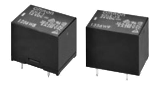
G5LE
PCB Power Relay
Cubic, Single-pole 10A Power
Relay
• Ideal for a wide variety of applications such as home appliances, OA
equipments, vending machines, etc.
• Ambient Operating Temperature 85°C
• UL class-B coil insulation for standard model.
• UL, CSA, EN standards approved and conforms to Electrical
Appliance and Material Safety Law (300 V max.).
RoHS Compliant
■Model Number Legend
■Application Examples
G5LE- @ @@
———
1 2 3
1. Number of Poles
1: 1-pole
2. Contact Form
None: SPDT (1c)
A:
SPST-NO (1a)
• Home appliances
• OA equipments
• Vending machines
3. Enclosure rating
None: Flux protection
4:
Fully sealed
G
5
L
E
■Ordering Information
■Characteristics
Flux protection
Fully sealed
Minimun
Rated coil
Rated coil
packing unit
Model
Model
Classification Contact form
voltage
voltage
5 VDC
5 VDC
SPDT (1c)
G5LE-1
12 VDC G5LE-14
12 VDC
24 VDC
24 VDC
100 pcs/
Standard
tray
5 VDC
5 VDC
SPST-NO (1a) G5LE-1A 12 VDC G5LE-1A4 12 VDC
24 VDC
24 VDC
Enclosure rating
Terminal
Shape
PCB
terminals
Note. When ordering, add the rated coil voltage to the model number.
Example: G5LE-1 DC5
Rated coil voltage
However, the notation of the coil voltage on the product case as well as on the packing will be marked
as @@ VDC.
■Ratings
Contact resistance *1
Operate time
Release time
Insulation resistance *2
Between
coil and
contacts
Dielectric
Between
strength
contacts of
the same
polarity
Impulse
between
withstand coil and
voltage
contacts
Destruction
Vibration
resistance
●Coil
Malfunction
Rated
voltage
Rated
current
(mA)
Coil
resistance
(Ω)
5 VDC
12 VDC
24 VDC
79.4
33.3
16.7
63
360
1,440
Must operate Must release
Max.
voltage
voltage
voltage
(V)
(V)
(V)
% of rated voltage
Power
consumption
(mW)
170%
at 23°C
Approx. 400
75% max.
10% min.
Shock
resistance
Destruction
Malfunction
Mechanical
Durability
Electrical
100 mΩ max.
10 ms max.
5 ms max.
100 MΩ min.
2,000 VAC, 50/60 Hz
for 1 min
750 VAC, 50/60 Hz
for 1 min
4,500 V (1.2×50 μs)
10 to 55 to 10 Hz,
0.75 mm single amplitude
(1.5 mm double amplitude)
10 to 55 to 10 Hz,
0.75 mm single amplitude
(1.5 mm double amplitude)
1,000 m/s2
100 m/s2
10,000,000 operations min.
(at 18,000 operations/hr)
100,000 operations min.
(at 1,800 operations/hr)
Note 1. The rated current and coil resistance are measured at a coil temperature of 23°C with a tolerance
of ±10%.
2. The operating characteristics are measured at a coil temperature of 23°C.
3. The “Max. voltage” is the maximum voltage that can be applied to the relay coil.
Failure rate (P level)
(reference value) *3
100 mA at 5 VDC
Ambient operating
temperature
-25°C to 85°C
(with no icing or
condensation)
●Contacts
Ambient operating
humidity
Weight
Item
Load
Contact type
Contact material
Rated load
Rated carry current
Max. switching voltage
Max. switching current
Resistive load
Inductive lead (cosφ = 0.4)
Single
Ag-alloy (Cd free)
10 A at 120 VAC; 8 A at 30 VDC
5 A at 120 VAC; 4 A at 30 VDC
10 A
250 VAC, 125 VDC (30 VDC when UL/CSA standard is applied)
10 A
5A
35% to 85%
Approx. 12 g
Note. The data given above are initial values
*1. Measurement conditions: 5 VDC, 1 A, voltage
drop method.
*2. Measurement conditions: The insulation
resistance was measured with a 500 VDC
megohmmeter at the same locations as the
dielectric strength was measured.
*3. This value was measured at a switching
frequency of 120 operations/min.
1
�G5LE
PCB Power Relay
■Engineering Data
●Durability
50
30
AC resistive
load
AC inductive
(cosφ 0.4)
10
7
5
3
● Ambient Temperature vs.
Maximum Coil Voltage
500
Maximum coil voltage (%)
Durability (x104 operations)
Switching current (A)
●Maximum Switching Capacity
300
30 VDC
resistive load
100
70
50
120 VAC
resistive load
30
200
180
160
140
1
0.7
0.5
10
7
5
DC resistive
load
0.3
0
120
3
10
30
50
100
500 1,000
0
250 VAC resistive load
120 VAC inductive
(cosφ = 0.4)
2
4
6
Switching voltage (V)
8
100
10
0
−25
12
20
30
40
50
Switching current (V)
60
70
80
90 100
Ambient temperature (°C)
Note. The maximum coil voltage refers to the maximum
value in a varying range of operating power
voltage, not a continuous voltage.
●Shock Malfunction
NO contact
Y
1,000
NC contact
G
5
L
E
1,000
X
1,000
Z’
500
Z Y
Z
1,000
500
X’
1,000
Z’
Y’
X’
X
1,000
Y’
2
Unit: m/s
Shock direction
Number of Relays:5 pcs
Test Conditions: Shock was applied 3 times in
each direction with and without
excitation and the level at which
the shock caused malfunction
was measured.
Rating:
100 m/s2
■Dimensions
G5LE-1 (SPDT contact)
G5LE-1A (SPST-NO contact)
(21.6)*
22.5 max.
Terminal Arrangement/
Internal Connections
(Bottom View)
PCB Mounting Holes
(Bottom View)
Tolerance: ±0.1 mm unless
specified
(15.6)*
16.5 max.
SPDT (1c)
SPDT (1c)
Five,1.3+0.2
0 dia. holes
(18.56)*
19.0 max.
(2.25)
0.5
12
3.5
0.2
1
1.2
*Average value
2
3
5
4
1
0.4
12.2
(2.55) 2
(5.75)
(2.25)
(Indicates average dimensions.)
G5LE-14 (SPDT contact)
G5LE-1A4 (SPST-NO contact)
(21.6)*
22.5 max.
(15.6)*
16.5 max.
SPST-NO (1a)
SPST-NO (1a)
Four,1.3+0.2
0 dia. holes
(2.25)
(18.5)*
19.0 max.
12
2
0.5
5
3.5
12.2
0.2
1
1.2
*Average value
0.4
(2.55) 2
(5.75)
(2.25)
(Indicates average dimensions.)
Note. Orientation marks are indicated as follows:
2
3
1
�G5LE
PCB Power Relay
■Approved Standards
UL Recognized:
(File No. E41643)
Model
Contact form
Coil
ratings
Contact ratings
G5LE
SPDT-NO (1a)
SPDT (1c)
5 to
24 VDC
10 A, 250 VAC
(general use) at 40°C
8 A, 30 VDC
(resistive load) at 40°C
TV-3 (N.O only) 40°C
CSA Certified:
Model
G5LE
Contact form
SPDT-NO (1a)
SPDT (1c)
Model
Contact form
G5LE
SPDT-NO (1a)
SPDT (1c)
Coil
ratings
Contact ratings
5 to
24 VDC
10 A, 250 VAC
(general use) at 40°C
8 A, 30 VDC
(resistive load) at
40°C
TV-3 (N.O only) 40°C
25,000
Contact form
SPDT-NO (1a)
SPDT (1c)
Number of test
operations
6,000
25,000
(Certificate No. 6850)
Coil
ratings
5, 12, 24
VDC
TÜV EN/IEC Certified:
G5LE
6,000
(File No. LR31928)
VDE EN/IEC Certified:
Model
Number of test
operations
Contact ratings
10 A, 250 VAC
(cosφ = 1) 85°C
Number of test
operations
50,000
(Certificate No. R50158258)
Coil
ratings
Contact ratings
5, 12, 24
VDC
2.5 A, 250 VAC
(cosφ = 0.4) 85°C
10 A, 250 VAC
(resistive load) at 85°C
8 A, 30 VAC
(resistive load) at 40°C
Number of test
operations
G
5
L
E
100,000
50,000
100,000
■Precautions
• Please refer to “PCB Relays Common Precautions” for correct use.
3
�G5LE
PCB Power Relay
G
5
L
E
• Application examples provided in this document are for reference only. In actual applications, confirm equipment functions and safety before using the product.
• Consult your OMRON representative before using the product under conditions which are not described in the manual or applying the product to nuclear control systems, railroad
systems, aviation systems, vehicles, combustion systems, medical equipment, amusement machines, safety equipment, and other systems or equipment that may have a serious
influence on lives and property if used improperly. Make sure that the ratings and performance characteristics of the product provide a margin of safety for the system or
equipment, and be sure to provide the system or equipment with double safety mechanisms.
Note: Do not use this document to operate the Unit.
OMRON Corporation
Electronic and Mechanical Components Company
4
Contact: www.omron.com/ecb
Cat. No. K100-E1-07
1116(0207)(O)
�


 工商网监
湘ICP备2023018690号
工商网监
湘ICP备2023018690号
