AX8052F131
SoC Ultra-Low Power
RF-Microcontroller for the
400 - 470 MHz and
800 - 940 MHz Bands
OVERVIEW
T h e A X 8 0 5 2 F 1 3 1 i s a s i n g l e c h i p u l t r a −l o w −p o w e r
RF−microcontroller SoC primarily for use in SRD bands. The on−chip
transmitter consists of a fully integrated RF front−end with modulator,
and demodulator. Base band data processing is implemented in an
advanced and flexible communication controller that enables user
friendly communication.
www.onsemi.com
1 40
QFN40 7x5, 0.5P
CASE 485EG
Features
SoC Ultra−low Power RF−microcontroller for Wireless
ORDERING INFORMATION
Communication Applications
Device
Package Shipping†
• QFN40 Package
AX8052F131−2−TB05
QFN28
500 /
• Supply Range 2.2 V − 3.6 V (1.8 V MCU)
(Pb−Free) Tape & Reel
AX8052F131−3−TB05
• −40°C to 85°C
• Ultra−low Power Consumption:
AX8052F131−2−TX30
QFN40
3,000 /
♦ CPU Active Mode 150 mA/MHz
(Pb−Free) Tape & Reel
AX8052F131−3−TX30
♦ Sleep Mode with 256 Byte RAM Retention and Wake−up Timer
running 900 nA
†For information on tape and reel specifications,
including part orientation and tape sizes, please
♦ Sleep Mode 4 kByte RAM Retention and Wake−up Timer running
refer to our Tape and Reel Packaging Specifications
1.9 mA
Brochure, BRD8011/D.
♦ Sleep Mode 8 kByte RAM Retention and Wake−up
Timer running 2.6 mA
• One General Purpose Master/Slave SPI
♦ Radio TX−mode 22 mA at 10 dBm Output Power
• Two Channel DMA Controller
• Multi−megabit/s AES Encryption/Decryption Engine
AX8052 Features
with True Random Number Generator (TRNG),
• Ultra−low Power MCU Core Compatible with Industry
supports AES−128, AES−192 and AES−256
Standard 8052 Instruction Set
NOTE: The AES Engine and the TRNG require
• Down to 250 nA Wake−up Current
Software Enabling and Support.
• Single Cycle/Instruction for many Instructions
• Ultra−low Power 10 kHz/640 Hz Wakeup Oscillator,
• 64 kByte In−system Programmable FLASH
with Automatic Calibration against a Precise Clock
• Code Protection Lock
• Internal 20 MHz RC Oscillator, with Automatic
• 8.25 kByte SRAM
Calibration against a Precise Clock for Flexible System
Clocking
• 3−wire (1 dedicated, 2 shared) In−circuit Debug
Interface
• Low Frequency Tuning Fork Crystal Oscillator for
Accurate Low Power Time Keeping
• Three 16−bit Timers with SD Output Capability
• Brown−out and Power−on−Reset Detection
• Two 16−bit Wakeup Timers
•
•
•
•
•
•
Two Input Captures
Two Output Compares with PWM Capability
10−bit 500 ksample/s Analog−to−Digital Converter
Temperature Sensor
Two Analog Comparators
Two UARTs
© Semiconductor Components Industries, LLC, 2016
August, 2017 − Rev. 4
High−performance RF Transmitter compatible to AX5031
400 − 470 MHz and 800 − 940 MHz SRD Bands
−5 dBm to +15 dBm Programmable Output
13 mA @ 0 dBm, 868 MHz
22 mA @ 10 dBm, 868 Mhz
•
•
•
•
1
Publication Order Number:
AX8052F131/D
�AX8052F131
• 44 mA @ 15 dBm, 868 Mhz
• Wide Variety of Shaped Modulations Supported
•
•
•
•
•
•
•
•
•
•
•
•
• Software Compatible to AX5031
Applications
(ASK, PSK, OQPSK, MSK, FSK, GFSK, 4−FSK)
Flexible Shaping for the Modulations
Data Rates
♦ 1 to 350 kbps for FSK, MSK
♦ 1 to 2000 kbps for ASK
♦ 10 to 2000 kbps for PSK
Fully Integrated RF Frequency Synthesizer with
Ultra−fast Settling Time for Low−power Consumption
RF Carrier Frequency and FSK Deviation
Programmable in 1Hz Steps
802.15.4 Compatible
Few External Components
Channel Hopping up to 2000 hops/s
Up to +16 dBm at 433 MHz Programmable Transmitter
Power Amplifier for Long Range Operation
Crystal Oscillator with Programmable
Transconductance and Programmable Internal Tuning
Capacitors for Low Cost Crystals
Differential Antenna Pins
Dual Frequency Registers
Internally Generated Coding for Forward Vitebri Error
Correction
400 − 470 MHz and 800 − 940 MHz Data Transmission in
the Short Range Devices (SRD) Band
• Suited for Systems targeting Compliance to
EN 300 220 Wide Band, FCC Part 15.247 and FCC
Part 15.249
• Suited for Systems targeting Compliance with Wireless
M−Bus S/T Mode
• 802.15.4 Compatible
• Telemetric Applications, Sensor Readout
• Toys
• Wireless Audio
• Automatic Meter Reading
• Wireless Networks
• Remote Keyless Entry
• Access Control
• Garage Door Openers
• Home Automation
• Pointing Devices and Keyboards
• Active RFID
www.onsemi.com
2
�AX8052F131
BLOCK DIAGRAM
AX8052F131
VDDA
FOUT
Crystal
Oscillator
typ. 16MHz
FXTAL
CLK16N
VREG
Voltage
Regulator
RF Frequency
Generation
Subsystem
FIFO
CLK16P
Modulator
PA
ANTN
Framing
Encoder
ANTP
Communication Controller &
Radio Interface Controller
Radio configuration
Divider
POR
FLASH
64k
GPIO
DMA
Controller
Timer
Counter 0
8k
AX8052
Timer
Counter 2
DBG_EN
Debug
Interface
Output
Compare0
RESET_N
GND
VDD_IO
System
Controller
wakeup
oscillator
tuning fork
crystal
oscillator
Input
Capture 0
AES
Crypto Engine
Input
Capture 1
ADC
Comparators
Temp Sensor
UART 0
SPI
master/slave
SFR-Bus
P-Bus
X-Bus
UART 1
I/O Multiplexer
Figure 1. Functional Block Diagram of the AX8052F131
www.onsemi.com
3
PB0
PB1
PB2
PB3
PB4
PB5
PB6
PB7
Output
Compare 1
wakeup
timer 2x
Reset, Clocks, Power
RC Oscillator
PA0
PA1
PA2
PA3
PA4
PA5
PA6
PA7
Timer
Counter 1
256
I-Bus
IRQ Req
RAM
DMA Req
SYSCLK
PC0
PC1
PC2
PC3
�AX8052F131
Table 1. PIN FUNCTION DESCRIPTIONS
Pin(s)
Type
CLK16P
Symbol
1
A
Crystal oscillator input/output (RF reference)
Description
CLK16N
2
A
Crystal oscillator input/output (RF reference)
VDDA
3
P
Power supply, must be supplied with regulated voltage VREG
GND
4
P
Ground
ANTP
5
A
Antenna output
ANTN
6
A
Antenna output
GND
7
P
Ground
VDDA
8
P
Power supply, must be supplied with regulated voltage VREG
SYSCLK
9
I/O/PU
Must be connected to SYSCLK at pin 13
T1
10
I/O/PU
Must be connected to T1 at pin 12
T2
11
I/O/PU
Must be left unconnected
T1
12
I/O/PU
Must be connected to T1 at pin 10
SYSCLK
13
I/O/PU
Must be connected to SYSCLK at pin 9
PC3
14
I/O/PU
General Purpose IO
PC2
15
I/O/PU
General Purpose IO
PC1
16
I/O/PU
General Purpose IO
PC0
17
I/O/PU
General Purpose IO
PB0
18
I/O/PU
General Purpose IO
PB1
19
I/O/PU
General Purpose IO
PB2
20
I/O/PU
General Purpose IO
PB3
21
I/O/PU
General Purpose IO
PB4
22
I/O/PU
General Purpose IO
PB5
23
I/O/PU
General Purpose IO
PB6
24
I/O/PU
General Purpose IO, DBG_DATA
PB7
25
I/O/PU
General Purpose IO, DBG_CLK
DBG_EN
26
I/PD
In−Circuit Debugger Enable
RESET_N
27
I/PU
Optional reset pin
If this pin is not used it must be connected to VDD_IO
GND
28
P
Ground
VDD_IO
29
P
Unregulated power supply (battery input)
PA0
30
I/O/A/PU
General Purpose IO
PA1
31
I/O/A/PU
General Purpose IO
PA2
32
I/O/A/PU
General Purpose IO
PA3
33
I/O/A/PU
General Purpose IO
PA4
34
I/O/A/PU
General Purpose IO
PA5
35
I/O/A/PU
General Purpose IO
PA6
36
I/O/A/PU
General Purpose IO
PA7
37
I/O/A/PU
General Purpose IO
PC7
38
I/O/PU
General Purpose IO
VREG
39
P
Regulated output voltage
VDDA pins must be connected to this supply voltage
A 1 mF low ESR capacitor to GND must be connected to this pin
www.onsemi.com
4
�AX8052F131
Table 1. PIN FUNCTION DESCRIPTIONS
Symbol
Pin(s)
Type
Description
GND
40
P
Ground
GND
Center pad
P
Ground on center pad of QFN, must be connected
All digital inputs are Schmitt trigger inputs, digital input
and output levels are LVCMOS/LVTTL compatible. Port A
Pins (PA0 − PA7) must not be driven above VDD_IO, all
other digital inputs are 5 V tolerant. Pull−ups are
programmable for all GPIO pins.
A = analog input
I = digital input signal
O = digital output signal
PU = pull−up
I/O = digital input/output signal
N = not to be connected
P = power or ground
PD = pull−down
Alternate Pin Functions
GPIO Pins are shared with dedicated Input/Output signals
of on−chip peripherals. The following table lists the
available functions on each GPIO pin.
Table 2. ALTERNATE PIN FUNCTIONS
GPIO
Alternate Functions
PA0
T0OUT
IC1
ADC0
PA1
T0CLK
OC1
ADC1
PA2
OC0
U1RX
ADC2
PA3
T1OUT
ADC3
LPXTALP
PA4
T1CLK
COMPO0
ADC4
LPXTALN
PA5
IC0
U1TX
ADC5
COMPI10
PA6
T2OUT
ADCTRIG
ADC6
COMPI01
PA7
T2CLK
COMPO1
ADC7
COMPI11
PB0
U1TX
IC1
EXTIRQ0
PB1
U1RX
OC1
PB2
IC0
T2OUT
PB3
OC0
T2CLK
PB4
U0TX
T1CLK
PB5
U0RX
T1OUT
PB6
DBG_DATA
EXTIRQ1
PB7
DBG_CLK
PC0
SSEL
T0OUT
EXTIRQ0
PC1
SSCK
T0CLK
COMPO1
PC2
SMOSI
U0TX
PC3
SMISO
U0RX
PC7
RPWRUP
www.onsemi.com
5
COMPO0
COMPI00
DSWAKE
�10
T1
12
6
18
www.onsemi.com
EXTIRQ0/IC1/U1TX/PB0
19
20
T2OUT/IC0/PB2
17
OC1/U1RX/PB1
16
EXTIRQ0/T0OUT/SSEL/PC0
15
COMPO1/T0CLK/SSCK/PC1
14
U0TX/SMOSI/PC2
13
COMPO0/U0RX/SMISO/PC3
SYSCLK
11
T1
T2
9
SYSCLK
GND
VREG
PC7/RPWRUP
PA7/ADC7/T2CLK/COMPO1/COMPI11
PA6/ADC6/T2OUT/ADCTRIG/COMPI01
PA5/ADC5/IC0/U1TX/COMPI10
PA4/ADC4/T1CLK/COMPO0/LPXTALN
PA3/ADC3/T1OUT/LPXTALP
PA2/ADC2/OC0/U1RX/COMPI00
PA1/ADC1/T0CLK/OC1
PA0/ADC0/T0OUT/IC1
VDD_IO
AX8052F131
Pinout Drawing
40
39
38
37
36
35
34
33
32
31
30
29
CLK16P
1
28
GND
CLK16N
2
27
RESET_N
VDDA
3
26
DBG_EN
GND
4
25
PB7/DBG_CLK
ANTP
5
24
PB6/DBG_DATA
ANTN
6
23
PB5/U0RX/T1OUT
GND
7
22
PB4/U0TX/T1CLK
VDDA
8
21
PB3/OC0/T2CLK/EXTIRQ1/DSWAKE
AX8052F131
QFN40
Figure 2. Pinout Drawing (Top View)
�AX8052F131
SPECIFICATIONS
Table 3. ABSOLUTE MAXIMUM RATINGS
Symbol
Description
Condition
Min
Max
Units
−0.5
5.5
V
100
mA
VDD_IO
Supply voltage
IDD
Supply current
Ptot
Total power consumption
800
mW
II1
DC current into any pin except ANTP, ANTN
−10
10
mA
II2
DC current into pins ANTP, ANTN
−100
100
mA
IO
Output Current
40
mA
Via
Input voltage ANTP, ANTN pins
−0.5
5.5
V
Input voltage digital pins
−0.5
5.5
V
Ves
Electrostatic handling
−2000
2000
V
Tamb
Operating temperature
HBM
−40
85
°C
Tstg
Storage temperature
−65
150
°C
Tj
Junction Temperature
150
°C
Stresses exceeding those listed in the Maximum Ratings table may damage the device. If any of these limits are exceeded, device functionality
should not be assumed, damage may occur and reliability may be affected.
1. Exposure to absolute maximum rating conditions for extended periods may affect device reliability.
DC Characteristics
Table 4. SUPPLIES
Symbol
Description
Condition
TAMB
Operational ambient temperature
VDD_IO
I/O and voltage regulator supply voltage
Min
Typ
Max
Units
−40
27
85
°C
TX operation
2.2
3.0
3.6
V
Transmitter switched off
1.8
3.0
3.6
V
VDDIO_R1
I/O voltage ramp for reset activation;
Note 1
Ramp starts at VDD_IO ≤ 0.1 V,
starting with AX8052F143−3 this
limitation to the VDD_IO ramp
for reset activation is no longer
necessary.
0.1
V/ms
VDDIO_R2
I/O voltage ramp for reset activation;
Note 1
Ramp starts at
0.1 V < VDD_IO < 0.7 V, starting
with AX8052F143−3 this limitation to the VDD_IO ramp for reset activation is no longer necessary.
3.3
V/ms
VREG
Internally regulated analog supply voltage
Power−down mode
AX5031_PWRMODE = 0x00
All other power modes
IDEEPSLEEP
Deep Sleep current
ISLEEP256PIN
Sleep current, 256 Bytes RAM retained
ISLEEP256
ISLEEP4K
ISLEEP8K
1.7
2.1
2.5
V
2.8
V
250
nA
Wakeup from dedicated pin
700
nA
Sleep current, 256 Bytes RAM retained
Wakeup Timer running at 640 Hz
1.1
mA
Sleep current, 4.25 kBytes RAM retained
Wakeup Timer running at 640 Hz
1.7
mA
Sleep current, 8.25 kBytes RAM retained
Wakeup Timer running at 640 Hz
2.4
mA
1. If VDD_IO ramps cannot be guaranteed, an external reset circuit is recommended for AX8052F131−2 and AX8052F131−2, see the
AX8052 Application Note: Power On Reset
2. The PA voltage is regulated to 2.5 V. For VDD_IO levels in the range of 2.2 V to 2.55 V the output power drops by typically 1 dBm.
www.onsemi.com
7
�AX8052F131
Table 4. SUPPLIES
Symbol
Description
ITX
Condition
Current consumption TX for maximum
power with default matching network at
3.3 V VDD_IO,
Note 2
Min
Typ
868 MHz, 15 dBm
22
868 MHz, 0 dBm
13
868 MHz, 15 dBm
45
433 MHz, 10 dBm
22
433 MHz, 0 dBm
13
433 MHz, 15 dBm
Max
Units
mA
45
TXvarvdd
Variation of output power over voltage
VDD_IO > 2.5 V, Note 2
±0.5
dB
TXvartemp
Variation of output power over temperature
VDD_IO > 2.5 V, Note 2
±0.5
dB
IMCU
Microcontroller running power consumption
All peripherals disabled
150
mA/
MHz
IVSUP
Voltage supervisor
Run and standby mode
85
mA
IXTALOSC
Crystal oscillator current
(RF reference oscillator)
16 MHz
160
mA
ILFXTALOSC
Low frequency crystal oscillator current
32 kHz
700
nA
IRCOSC
Internal oscillator current
20 MHz
210
mA
ILPOSC
Internal Low Power Oscillator current
10 kHz
650
nA
640 Hz
210
nA
311 kSample/s, DMA 5 MHz
1.1
mA
IADC
ADC current
1. If VDD_IO ramps cannot be guaranteed, an external reset circuit is recommended for AX8052F131−2 and AX8052F131−2, see the
AX8052 Application Note: Power On Reset
2. The PA voltage is regulated to 2.5 V. For VDD_IO levels in the range of 2.2 V to 2.55 V the output power drops by typically 1 dBm.
Note on current consumption in TX mode
To achieve best output power the matching network has to
be optimized for the desired output power and frequency. As
a rule of thumb a good matching network produces about
50% efficiency with the AX8052F131 power amplifier
although over 90% are theoretically possible. A typical
matching network has between 1 dB and 2 dB loss (Ploss).
The current consumption can be calculated as
I TX[mA] +
1
PA efficiency
10
P out[dBm])P loss[dB]
10
B 2.5V ) I offset
Ioffset is about 12 mA for the VCO at 400 − 470 MHz and
11 mA for 800 − 940 MHz. The following table shows
calculated current consumptions versus output power for
Ploss = 1 dB, PAefficiency = 0.5 and Ioffset= 11 mA at 868 MHz.
Table 5.
Pout [dBm]
I [mA]
0
13.0
1
13.2
2
13.6
3
14.0
4
14.5
5
15.1
6
16.0
7
17.0
8
18.3
9
20.0
10
22.0
11
24.6
12
27.96
13
32.1
14
37.3
15
43.8
The AX8052F131 power amplifier runs from the
regulated VDD supply and not directly from the battery.
This has the advantage that the current and output power do
not vary much over supply voltage and temperature from
2.55 V to 3.6 V supply voltage. Between 2.55 V and 2.2 V
a drop of about 1 dB in output power occurs.
www.onsemi.com
8
�AX8052F131
Table 6. LOGIC
Symbol
Description
Condition
Min
Typ
Max
Units
Digital Inputs
VDD_IO = 3.3 V
VT+
Schmitt trigger low to high threshold point
1.55
V
VT−
Schmitt trigger high to low threshold point
VIL
Input voltage, low
VIH
Input voltage, high
2.0
VIPA
Input voltage range, Port A
−0.5
VDD_IO
V
VIPBC
Input voltage range, Ports B, C
−0.5
5.5
V
IL
Input leakage current
−10
10
mA
RPU
Programmable Pull−Up Resistance
1.25
V
0.8
V
V
65
kW
Digital Outputs
IOH
P[ABC]x Output Current, high
VOH = 2.4 V
8
mA
IOL
P[ABC]x Output Current, low
VOL = 0.4 V
8
mA
IOH
SYSCLK Output Current, high
VOH = 2.4 V
8
mA
IOL
SYSCLK Output Current, low
VOL = 0.4 V
8
mA
IOZ
Tri−state output leakage current
−10
10
mA
AC Characteristics
Table 7. CRYSTAL OSCILLATOR (RF REFERENCE OSCILLATOR)
Symbol
Description
Condition
Min
Typ
Max
Units
15.5
16
25
MHz
fXTAL
Crystal frequency
Notes 1, 3
gmosc
Transconductance oscillator
AX5031_XTALOSCGM = 0000
1
AX5031_XTALOSCGM = 0001
2
AX5031_XTALOSCGM = 0010
default
3
AX5031_XTALOSCGM = 0011
4
AX5031_XTALOSCGM = 0100
5
AX5031_XTALOSCGM = 0101
6
AX5031_XTALOSCGM = 0110
6.5
AX5031_XTALOSCGM = 0111
7
AX5031_XTALOSCGM = 1000
7.5
AX5031_XTALOSCGM = 1001
8
AX5031_XTALOSCGM = 1010
8.5
AX5031_XTALOSCGM = 1011
9
AX5031_XTALOSCGM = 1100
9.5
AX5031_XTALOSCGM = 1101
10
AX5031_XTALOSCGM = 1110
10.5
AX5031_XTALOSCGM = 1111
11
AX5031_XTALCAP = 000000
default
2
AX5031_XTALCAP = 111111
33
Cosc
Programmable tuning capacitors at pins
CLK16N and CLK16P
www.onsemi.com
9
mS
pF
�AX8052F131
Table 7. CRYSTAL OSCILLATOR (RF REFERENCE OSCILLATOR)
Cosc−lsb
Programmable tuning capacitors, increment per LSB of AX5031_XTALCAP
fext
External clock input (TCXO)
Aosc
Oscillator amplitude at pin CLK16P
RINosc
Input DC impedance
0.5
Notes 2, 3
15.5
15
pF
25
0.5
10
MHz
V
kW
1. Tolerances and start−up times depend on the crystal used. Depending on the RF frequency and channel spacing the IC must be calibrated
to the exact crystal frequency using the readings of the register AX5031_TRKFREQ.
2. If an external clock is used, it should be input via an AC coupling at pin CLK16P with the oscillator powered up and
AX5031_XTALCAP = 000000
3. Lower frequencies than 15.5 MHz or higher frequencies than 25 MHz can be used. However, not all typical RF frequencies can then be
generated.
www.onsemi.com
10
�AX8052F131
Table 8. RF FREQUENCY GENERATION SUBSYSTEM (SYNTHESIZER)
Symbol
Description
Condition
Min
Typ
Max
fREF
Reference frequency
Note 1
frange_hi
Frequency range
BANDSEL = 0
800
940
BANDSEL = 1
400
470
frange_low
fRESO
Frequency resolution
BW1
Synthesizer loop bandwidth
VCO current: VCOI = 001
16
24
1
100
BW2
Loop filter configuration: FLT = 01
Charge pump current: PLLCPI = 001
50
BW3
Loop filter configuration: FLT = 11
Charge pump current: PLLCPI = 010
200
BW4
Loop filter configuration: FLT = 10
Charge pump current: PLLCPI = 010
500
Loop filter configuration: FLT = 01
Charge pump current: PLLCPI = 010
15
Loop filter configuration: FLT = 01
Charge pump current: PLLCPI = 001
30
Tset3
Loop filter configuration: FLT = 11
Charge pump current: PLLCPI = 010
7
Tset4
Loop filter configuration: FLT = 10
Charge pump current: PLLCPI = 010
3
Loop filter configuration: FLT = 01
Charge pump current: PLLCPI = 010
25
Loop filter configuration: FLT = 01
Charge pump current: PLLCPI = 001
50
Tstart3
Loop filter configuration: FLT = 11
Charge pump current: PLLCPI = 010
12
Tstart4
Loop filter configuration: FLT = 10
Charge pump current: PLLCPI = 010
5
Tset2
Tstart1
Tstart2
PN8681
Synthesizer settling time for
1 MHz step
VCO current: VCO_I = 001
Synthesizer start−up time if
crystal oscillator and reference are running
VCO current: VCO_I = 001
Synthesizer phase noise
Loop filter configuration:
FLT = 01
Charge pump current: PLLCPI = 010
VCO current: VCO_I = 001
PN4331
PN8682
PN4332
Synthesizer phase noise
Loop filter configuration:
FLT = 01
Charge pump current: PLLCPI = 001
VCO current: VCO_I = 001
868 MHz, 50 kHz from carrier
−85
868 MHz, 100 kHz from carrier
−90
868 MHz, 300 kHz from carrier
−100
868 MHz, 2 MHz from carrier
−110
433 MHz, 50 kHz from carrier
−90
433 MHz, 100 kHz from carrier
−95
433 MHz, 300 kHz from carrier
−105
433 MHz, 2 MHz from carrier
−115
868 MHz, 50 kHz from carrier
−80
868 MHz, 100 kHz from carrier
−90
868 MHz, 300 kHz from carrier
−105
868 MHz, 2 MHz from carrier
−115
433 MHz, 50 kHz from carrier
−90
433 MHz, 100 kHz from carrier
−95
433 MHz, 300 kHz from carrier
−110
433 MHz, 2 MHz from carrier
−122
1. ASK, PSK and 1−200 kbps FSK with 16 MHz crystal, 200−350 kbps FSK with 24 MHz crystal.
www.onsemi.com
11
MHz
MHz
Hz
Loop filter configuration: FLT = 01
Charge pump current: PLLCPI = 010
Tset1
Units
kHz
ms
ms
dBc/Hz
dBc/Hz
�AX8052F131
Table 9. TRANSMITTER
Symbol
SBR
Description
Condition
Signal bit rate
Max
Units
ASK
Min
1
Typ
2000
kbps
PSK
10
2000
FSK, (Note 2)
1
350
802.15.4 (DSSS)
ASK and PSK
1
40
802.15.4 (DSSS)
FSK
1
16
PTX868
Transmitter power @ 868 MHz
TXRNG = 1111
15
dBm
PTX433
Transmitter power @ 433 MHz
TXRNG = 1111
16
dBm
(Note 1)
−50
dBc
PTX868−harm2
PTX868−harm3
Emission @
2nd
harmonic
Emission @
3rd
harmonic
−55
1. Additional low−pass filtering was applied to the antenna interface, see applications section.
2. 1 − 200 kbps with a 16 MHz crystal, 200 − 350 kbps with 24 MHz crystal
Table 10. LOW FREQUENCY CRYSTAL OSCILLATOR
Symbol
Description
fLPXTAL
Crystal frequency
gmlpxosc
Transconductance oscillator
RINlpxosc
Condition
Min
Typ
Max
Units
32
150
kHz
LPXOSCGM = 00110
3.5
LPXOSCGM = 01000
4.6
LPXOSCGM = 01100
6.9
LPXOSCGM = 10000
9.1
Input DC impedance
ms
10
MW
Table 11. INTERNAL LOW POWER OSCILLATOR
Symbol
fLPOSC
Description
Oscillation Frequency
Min
Typ
Max
Units
LPOSCFAST = 0
Factory calibration applied. Over the
full temperature and voltage range
Condition
630
640
650
Hz
LPOSCFAST = 1
Factory calibration applied. Over the
full temperature and voltage range
10.08
10.24
10.39
kHz
Min
Typ
Max
Units
19.8
20
20.2
MHz
Table 12. INTERNAL RC OSCILLATOR
Symbol
fFRCOSC
Description
Oscillation Frequency
Condition
Factory calibration applied. Over the
full temperature and voltage range
www.onsemi.com
12
�AX8052F131
Table 13. MICROCONTROLLER
Symbol
Description
Condition
Min
Typ
Max
Units
TSYSCLKL
SYSCLK Low
27
ns
TSYSCLKH
SYSCLK High
21
ns
TSYSCLKP
SYSCLK Period
47
ns
TFLWR
FLASH Write Time
2 Bytes
20
ms
TFLPE
FLASH Page Erase
1 kBytes
2
ms
TFLE
FLASH Secure Erase
64 kBytes
TFLEND
FLASH Endurance: Erase Cycles
TFLRETroom
FLASH Data Retention
TFLREThot
10 000
25°C
See Figure 3 for the lower limit
set by the memory qualification
100
85°C
See Figure 3 for the lower limit
set by the memory qualification
10
10
ms
100 000
Cycles
Years
Data retention time [years]
100000
10000
1000
100
10
15
25
35
45
55
Temperature [5C]
65
75
85
Figure 3. FLASH Memory Qualification Limit for Data Retention after 10k Erase Cycles
www.onsemi.com
13
�AX8052F131
Table 14. ADC / COMPARATOR / TEMPERATURE SENSOR
Symbol
Description
Condition
Min
ADCSR
ADC sampling rate GPADC mode
30
ADCSR_T
ADC sampling rate temperature sensor mode
10
ADCRES
ADC resolution
VADCREF
ADC reference voltage & comparator internal
reference voltage
ZADC00
Input capacitance
DNL
Differential nonlinearity
INL
Integral nonlinearity
OFF
Offset
GAIN_ERR
Gain error
Typ
15.6
Max
Units
500
kHz
30
kHz
10
0.95
1
Bits
1.05
V
2.5
pF
±1
LSB
±1
LSB
3
LSB
0.8
%
ADC in Differential Mode
VABS_DIFF
Absolute voltages & common mode voltage in
differential mode at each input
VFS_DIFF01
Full swing input for differential signals
VFS_DIFF10
0
VDD_IO
V
Gain x1
−500
500
mV
Gain x10
−50
50
mV
ADC in Single Ended Mode
VMID_SE
Mid code input voltage in single ended mode
VIN_SE00
Input voltage in single ended mode
VFS_SE01
Full swing input for single ended signals
0.5
Gain x1
V
0
VDD_IO
V
0
1
V
Comparators
VCOMP_ABS
Comparator absolute input voltage
0
VDD_IO
V
VCOMP_COM
Comparator input common mode
0
VDD_IO −
0.8
V
VCOMPOFF
Comparator input offset voltage
20
mV
Temperature Sensor
TRNG
Temperature range
TRES
Temperature resolution
TERR_CAL
Temperature error
−40
85
0.1607
Factory calibration
applied
www.onsemi.com
14
−2
°C
°C/LSB
2
°C
�AX8052F131
CIRCUIT DESCRIPTION
The AX8052F131 sends data in frames. This standard
operation mode is called Frame Mode. Pre and post ambles
as well as checksums can be generated automatically.
AX8052F131 supports any data rate from 1 kbps to
350 kbps for FSK and MSK, from 1 kbps to 2000 kbps for
ASK and from 10 kbps to 2000 kbps for PSK. To achieve
optimum performance for specific data rates and
modulation schemes several register settings to configure
the AX8052F131 are necessary, they are outlined in the
following, for details see the AX5031 Programming
Manual.
Spreading is possible on all data rates and modulation
schemes. The net transfer rate is reduced by a factor of 15 in
this case. For ZigBee either 600 or 300 kbps modes have to
be chosen.
The transmitter supports multi−channel operation for all
data rates and modulation schemes.
The AX8052F131 is a single chip ultra−low−power
RF−microcontroller SoC primarily for use in SRD bands.
The on−chip transmitter consists of a fully integrated RF
front−end with modulator, and demodulator. Base band data
processing is implemented in an advanced and flexible
communication controller that enables user friendly
communication.
The AX8052F131 contains a high speed microcontroller
compatible to the industry standard 8052 instruction set. It
contains 64 kBytes of FLASH and 8.25 kBytes of internal
SRAM.
The AX8052F131 features 3 16−bit general purpose
timers with SD capability, 2 output compare units for
generating PWM signals, 2 input compare units to record
timings of external signals, 2 16−bit wakeup timers, a
watchdog timer, 2 UARTs, a Master/Slave SPI controller, a
10−bit 500 kSample/s A/D converter, 2 analog comparators,
a temperature sensor, a 2 channel DMA controller, and a
dedicated AES crypto controller. Debugging is aided by a
dedicated hardware debug interface controller that connects
using a 3−wire protocol (1 dedicated wire, 2 shared with
GPIO) to the PC hosting the debug software.
While the radio carrier can only be clocked by the crystal
oscillator (carrier stability requirements dictate a high
stability reference clock in the MHz range), the
microcontroller and its peripherals provide extremely
flexible clocking options. The system clock that clocks the
microcontroller, as well as peripheral clocks, can be selected
from one of the following clock sources: the crystal
oscillator, an internal high speed 20 MHz oscillator, an
internal low speed 640 Hz/10 kHz oscillator, or the low
frequency crystal oscillator. Prescalers offer additional
flexibility with their programmable divide by a power of two
capability. To improve the accuracy of the internal
oscillators, both oscillators may be slaved to the crystal
oscillator.
AX8052F131 can be operated from a 2.2 V to 3.6 V power
supply over a temperature range of –40°C to 85°C, it
consumes 11 − 45 mA for transmitting, depending on the
output power.
The AX8052F131 features make it an ideal interface for
integration into various battery powered SRD solutions such
as ticketing or as transmitter for telemetric applications e.g.
in sensors. As primary application, the transmitter is
intended for UHF radio equipment in accordance with the
European Telecommunication Standard Institute (ETSI)
specification EN 300 220−1 and the US Federal
Communications Commission (FCC) standard CFR47, part
15. The use of AX8052F131 in accordance to FCC Par
15.247, allows for improved range in the 915 MHz band.
Additionally AX8052F131 is compatible with the low
frequency standards of 802.15.4 (ZigBee) and suited for
systems targeting compliance with Wireless M−Bus
standard EN 13757−4:2005
Microcontroller
The AX8052 microcontroller core executes the industry
standard 8052 instruction set. Unlike the original 8052,
many instructions are executed in a single cycle. The system
clock and thus the instruction rate can be programmed freely
from DC to 20 MHz.
Memory Architecture
The AX8052 Microcontroller features the highest
bandwidth memory architecture of its class. Figure 4 shows
the memory architecture. Three bus masters may initiate bus
cycles:
• The AX8052 Microcontroller Core
• The Direct Memory Access (DMA) Engine
• The Advanced Encryption Standard (AES) Engine
Bus targets include:
• Two individual 4 kBytes RAM blocks located in X
address space, which can be simultaneously accessed
and individually shut down or retained during sleep
mode
• A 256 Byte RAM located in internal address space,
which is always retained during sleep mode
• A 64 kBytes FLASH memory located in code space.
• Special Function Registers (SFR) located in internal
address space accessible using direct address mode
instructions
• Additional Registers located in X address space
(X Registers)
The upper half of the FLASH memory may also be
accessed through the X address space. This simplifies and
makes the software more efficient by reducing the need for
generic pointers.
NOTE: Generic pointers include, in addition to the
address, an address space tag.
www.onsemi.com
15
�AX8052F131
The 4 word × 16 bit fully associative cache and a pre−fetch
controller hide the latency of the FLASH.
SFR Registers are also accessible through X address
space, enabling indirect access to SFR registers. This allows
driver code for multiple identical peripherals (such as
UARTs or Timers) to be shared.
AES
Cache
AX8052
DMA
X Bus
Arbiter
Arbiter
Arbiter
XRAM
XRAM
X Registers
0000−0FFF
1000−1FFF
4000−7FFF
SFR Bus
IRAM Bus
Arbiter
Prefetch
Code Bus
Arbiter
Arbiter
SFR Registers
IRAM
FLASH
80−FF
00−FF
0000−FFFF
Figure 4. AX8052 Memory Architecture
The AES engine accesses memory 16 bits at a time. It is
therefore slightly faster to align its buffers on even
addresses.
The AX8052 Memory Architecture is fully parallel. All
bus masters may simultaneously access different bus targets
during each system clock cycle. Each bus target includes an
arbiter that resolves access conflicts. Each arbiter ensures
that no bus master can be starved.
Both 4 kBytes RAM blocks may be individually retained
or switched off during sleep mode. The 256 Byte RAM is
always retained during sleep mode.
Memory Map
The AX8052, like the other industry standard 8052
compatible microcontrollers, uses a Harvard architecture.
Multiple address spaces are used to access code and data.
Figure 5 shows the AX8052 memory map.
www.onsemi.com
16
�AX8052F131
I (internal) Space
Address
P (Code) Space
X Space
direct access
0000−007F
indirect access
IRAM
IRAM
XRAM
0080−00FF
SFR
0100−1FFF
IRAM
2000−207F
2080−3F7F
FLASH
3F80−3FFF
SFR
4000−4FFF
RREG
5000−5FFF
RREG (nb)
6000−7FFF
XREG
8000−FBFF
FLASH
FC00−FFFF
Calibration Data
Calibration Data
Figure 5. AX8052 Memory Map
AX5031 Programming Manual are relative to the beginning
of RREG, i.e. 0x4000 must be added to these addresses. It
is recommended that the provided AX8052F131.h header
file is used; Radio Registers are prefixed with AX5031_ in
the AX8052F131.h header file to avoid clashes of
same−name Radio Registers with AX8052 registers.
Normally, accessing Radio Registers through the RREG
address range is adequate. Since Radio Register accesses
have a higher latency than other AX8052 registers, the
AX8052 provides a method for non−blocking access to the
Radio Registers. Accessing the RREG (nb) address range
initiates a Radio Register access, but does not wait for its
completion. The details of mechanism is documented in the
Radio Interface section of the AX8052 Programming
Manual.
The FLASH memory is organized as 64 pages of 1 kBytes
each. Each page can be individually erased. The write word
size is 16 Bits. The last 1 kByte page is dedicated to factory
calibration data and should not be overwritten.
The AX8052 uses P or Code Space to access its program.
Code space may also be read using the MOVC instruction.
Smaller amounts of data can be placed in the Internal (see
Note) or Data Space. A distinction is made in the upper half
of the Data Space between direct accesses (MOV reg,addr;
MOV addr,reg) and indirect accesses (MOV reg,@Ri;
MOV @Ri,reg; PUSH; POP); Direct accesses are routed to
the Special Function Registers, while indirect accesses are
routed to the internal RAM.
NOTE: The origin of Internal versus External (X) Space
is historical. External Space used to be outside
of the chip on the original 8052
Microcontrollers.
Large amounts of data can be placed in the External or X
Space. It can be accessed using the MOVX instructions.
Special Function Registers, as well as additional
Microcontroller Registers (XREG) and the Radio Registers
(RREG) are also mapped into the X Space.
Detailed documentation of the Special Function Registers
(SFR) and additional Microcontroller Registers can be
found in the AX8052 Programming Manual.
The Radio Registers are documented in the AX5031
Programming Manual. Register Addresses given in the
Power Management
The microcontroller power mode can be selected
independently from the transmitter. The microcontroller
supports the following power modes:
www.onsemi.com
17
�AX8052F131
Table 15. POWER MANAGEMENT
PCON
register
Name
Description
00
RUNNING
The microcontroller and all peripherals are running. Current consumption depends on the system clock
frequency and the enabled peripherals and their clock frequency.
01
STANDBY
The microcontroller is stopped. All register and memory contents are retained. All peripherals continue to
function normally. Current consumption is determined by the enabled peripherals. STANDBY is exited
when any of the enabled interrupts become active.
10
SLEEP
The microcontroller and its peripherals, except GPIO and the system controller, are shut down. Their register settings are lost. The internal RAM is retained. The external RAM is split into two 4 kByte blocks. Software can determine individually for both blocks whether contents of that block are to be retained or lost.
SLEEP can be exited by any of the enabled GPIO or system controller interrupts. For most applications
this will be a GPIO or wakeup timer interrupt.
11
DEEPSLEEP
The microcontroller, all peripherals and the transceiver are shut down. Only 4 bytes of scratch RAM are
retained. DEEPSLEEP can only be exited by tying the PB3 pin low.
Clocking
WDT
FRCOSC
Calib
Wakeup
Timer
Interrupt
Prescaler
÷1,2,4,...
System Clock
LPOSC
FRCOSC
Glitch Free Clock Switch
LPOSC
Calib
Internal Reset
XOSC
Clock
Monitor
LPXOSC
SYSCLK
Figure 6. Clock System Diagram
The system clock can be derived from any of the following
clock sources:
• The crystal oscillator (RF reference oscillator, typically
16 MHz, via SYSCLK)
• The low speed crystal oscillator (typical 32 kHz tuning
fork)
• The internal high speed RC (20 MHz) oscillator
• The internal low power (640 Hz/10 kHz) oscillator
An additional pre−scaler allows the selected oscillator to
be divided by a power of two. After reset, the
microcontroller starts with the internal high speed RC
oscillator selected and divided by two. I.e. at start−up, the
microcontroller runs with 10 MHz ± 10%. Clocks may be
switched any time by writing to the CLKCON register. In
order to prevent clock glitches, the switching takes
approximately 2·(T1+T2), where T1 and T2 are the periods
www.onsemi.com
18
�AX8052F131
without key knowledge; secure erase ensures that the main
FLASH array is completely erased before erasing the key,
reverting the chip into factory state.
The DebugLink peripheral looks like an UART to the
microcontroller, and allows exchange of data between the
microcontroller and the host PC without disrupting program
execution.
of the old and the new clock. Switching may take longer if
the new oscillator first has to start up. Internal oscillators
start up instantaneously, but crystal oscillators may take a
considerable amount of time to start the oscillation.
CLKSTAT can be read to determine the clock switching
status.
A programmable clock monitor resets the CLKCON
register when no system clock transitions are found during
a programmable time interval, thus reverts to the internal RC
oscillator.
Both internal oscillators can be slaved to one of the crystal
oscillators to increase the accuracy of the oscillation
frequency. While the reference oscillator runs, the internal
oscillator is slaved to the reference frequency by a digital
frequency locked loop. When the reference oscillator is
switched off, the internal oscillator continues to run
unslaved with the last frequency setting.
Timer, Output Compare and Input Capture
The AX8052F131 features three general purpose 16−bit
timers. Each timer can be clocked by the system clock, any
of the available oscillators, or a dedicated input pin. The
timers also feature a programmable clock inversion, a
programmable prescaler that can divide by powers of two,
and an optional clock synchronization logic that
synchronizes the clock to the system clock. All three
counters are identical and feature four different counting
modes, as well as a SD mode that can be used to output an
analog value on a dedicated digital pin only employing a
simple RC lowpass filter.
Two output compare units work in conjunction with one
of the timers to generate PWM signals.
Two input capture units work in conjunction with one of
the timers to measure transitions on an input signal.
For software timekeeping, two additional 16−bit wakeup
timers with 4 16−bit event registers are provided, generating
an interrupt on match events.
Reset and Interrupts
After reset, the microcontroller starts executing at address
0x0000. Several events can lead to resetting the
microcontroller core:
• POR or hardware RESET_N pin activated and released
• Leaving SLEEP or DEEPSLEEP mode
• Watchdog Reset
• Software Reset
The reset cause can be determined by reading the PCON
register.
The microcontroller supports 22 interrupt sources. Each
interrupt can be individually enabled and can be
programmed to have one of two possible priorities. The
interrupt vectors are located at 0x0003, 0x000B,…,
0x00AB.
UART
The AX8052F131 features two universal asynchronous
receiver transmitters. They use one of the timers as baud rate
generator. Word length can be programmed from 5 to 9 bits.
SPI Master/Slave Controller
The AX8052F131 features a master/slave SPI controller.
Both 3 and 4 wire SPI variants are supported. In master
mode, any of the on−chip oscillators or the system clock may
be selected as clock source. An additional prescaler with
divide by two capability provides additional clocking
flexibility. Shift direction, as well as clock phase and
inversion, are programmable.
Debugging
A hardware debug unit considerably eases debugging
compared to other 8052 microcontrollers. It allows to
reliably stop the microcontroller at breakpoints even if the
stack is smashed. The debug unit communicates with the
host PC running the debugger using a 3 wire interface. One
wire is dedicated (DBG_EN), while two wires are shared
with GPIO pins (PB6, PB7). When DBG_EN is driven high,
PB6 and PB7 convert to debug interface pins and the GPIO
functionality is no longer available. A pin emulation feature
however allows bits PINB[7:6] to be set and PORTB[7:6]
and DIRB[7:6] to be read by the debugger software. This
allows for example switches or LEDs connected to the PB6,
PB7 pins to be emulated in the debugger software whenever
the debugger is active.
In order to protect the intellectual property of the firmware
developer, the debug interface can be locked using a
developer−selectable 64−bit key. The debug interface is then
disabled and can only be enabled with the knowledge of this
64−bit key. Therefore, unauthorized persons cannot read the
firmware through the debug interface, but debugging is still
possible for authorized persons. Secure erase can be initiated
ADC, Analog Comparators and Temperature Sensor
The AX8052F131 features a 10−bit, 500 kSample/s
Analog to Digital converter. Figure 7 shows the block
diagram of the ADC. The ADC supports both single ended
and differential measurements. It uses an internal reference
of 1 V. ×1, ×10 and ×0.1 gain modes are provided. The ADC
may digitize signals on PA0…PA7, as well as VDD_IO and
an internal temperature sensor. The user can define four
channels which are then converted sequentially and stored
in four separate result registers. Each channel configuration
consists of the multiplexer and the gain setting.
The AX8052F131 contains an on−chip temperature
sensor. Built−in calibration logic allows the temperature
sensor to be calibrated in °C, °F or any other user defined
temperature scale.
www.onsemi.com
19
�AX8052F131
System Clock
SYSCLK
LPXOSC
XOSC
VDDIO
reference. The comparator output can be routed to a
dedicated digital output pin or can be read by software. The
comparators are clocked with the system clock.
LPOSC
Temperature
Sensor
FRCOSC
ADCCLKSRC
The AX8052F131 also features two analog comparators.
Each comparator can either compare two voltages on
dedicated PA pins, or one voltage against the internal 1 V
Free Running
One Shot
PA6
Timer 0
PA5
Timer 1
Prescaler
÷1,2,4,8,...
PA7
PA4
PA3
Timer 2
PC4
PA2
PA1
ADCCONV
Clock
PA0
Trigger
ADC Core
PPP
Ref
x 0.1, x 1, x 10
Gain
ADC Result
VREF
1V
0.5 V
Single Ended
NNN
ACOMP0IN
ACOMP0ST/PA4/PC3
ACOMP0INV
ACOMP0REF
System Clock
ACOMP1IN
ACOMP1ST/PA7/PC1
ACOMP1INV
ACOMP1REF
Figure 7. ADC Block Diagram
DMA Controller
The DMA channels access XRAM in a cycle steal fashion.
They access XRAM whenever XRAM is not used by the
microcontroller. Their priority is lower than the
microcontroller, thus interfering very little with the
microcontroller. Additional logic prevents starvation of the
DMA controller.
The AX8052F131 features a dual channel DMA engine.
Each DMA channel can either transfer data from XRAM to
almost any peripheral on chip, or from almost any peripheral
to XRAM. Both channels may also be cross−linked for
memory−memory transfers. The DMA channels use buffer
descriptors to find the buffers where data is to be retrieved
or placed, thus enabling very flexible buffering strategies.
www.onsemi.com
20
�AX8052F131
AES Engine
The AX8052F131 contains a dedicated engine for the
government mandated Advanced Encryption Standard
(AES). It features a dedicated DMA engine and reads input
data as well as key stream data from the XRAM, and writes
output data into a programmable buffer in the XRAM. The
round number is programmable; the chip therefore supports
AES−128, AES−192, and AES−256, as well as higher
security proprietary variants. Keystream (key expansion) is
performed in software, adding to the flexibility of the AES
engine. ECB (electronic codebook), CFB (cipher feedback)
and OFB (output feedback) modes are directly supported
without software intervention.
external reset circuit is recommended. For detailed
recommendations and requirements see the AX8052
Application Note: Power On Reset.
After POR or reset all registers are set to their default
values.
The RESET_N pin contains a weak pull−up. However, it
is strongly recommended to connect the RESET_N pin to
VDD_IO if not used, for additional robustness.
The AX8052F131 can be reset by software as well. The
microcontroller is reset by writing 1 to the SWRESET bit of
the PCON register. The transmitter can be reset by first
writing 1 and then 0 to the RST bit in the
AX5031_PWRMODE register.
Crystal Oscillator (RF Reference Oscillator)
Ports
The on−chip crystal oscillator allows the use of an
inexpensive quartz crystal as the RF generation subsystem’s
timing reference. Although a wider range of crystal
frequencies can be handled by the crystal oscillator circuit,
it is recommended to use 16 MHz as reference frequency for
ASK and PSK modulations independent of the data rate. For
FSK it is recommended to use a 16 MHz crystal for data rates
below 200 kbps and 24 MHz for data rates above 200 kbps.
The oscillator circuit is enabled by programming the
AX5031_PWRMODE register. At power−up it is not
enabled.
To adjust the circuit’s characteristics to the quartz crystal
being used, without using additional external components,
both the transconductance and the tuning capacitance of the
crystal oscillator can be programmed.
The transconductance is programmed via register bits
XTALOSCGM[3:0] in register AX5031_XTALOSC.
The integrated programmable tuning capacitor bank
makes it possible to connect the oscillator directly to pins
CLK16N and CLK16P without the need for external
capacitors. It is programmed using bits XTALCAP[5:0] in
register AX5031_XTALCAP.
Alternatively a single ended reference (TCXO, CXO)
may be used. The CMOS levels should be applied to
CLK16P via an AC coupling with the crystal oscillator
enabled.
VDDIO
PORTx.y
DIRx.y
65 kW
Special Function
PALTx.y
INTCHGx.y
Interrupt
PINx.y
PINx read clock
ANALOGx.y
Figure 8. Port Pin Schematic
Figure 8 shows the GPIO logic. The DIR register bit
determines whether the port pin acts as an output (1) or an
input (0).
If configured as an output, the PALT register bit
determines whether the port pin is connected to a peripheral
output (1), or used as a GPIO pin (0). In the latter case, the
PORT register bit determines the port pin drive value.
If configured as an input, the PORT register bit determines
whether a pull−up resistor is enabled (1) or disabled (0).
Inputs have Schmitt−trigger characteristic. Port A inputs
may be disabled by setting the ANALOGA register bit; this
prevents additional current consumption if the voltage level
of the port pin is mid−way between logic low and logic high,
when the pin is used as an analog input.
Port A, B and C pins may interrupt the microcontroller if
their level changes. The INTCHG register bit enables the
interrupt. The PIN register bit reflects the value of the port
pin. Reading the PIN register also resets the interrupt if
interrupt on change is enabled.
SYSCLK Output
The SYSCLK pin outputs the RF reference clock signal
divided by a programmable integer. Divisions from 1 to
2048 are possible. For divider ratios > 1 the duty cycle is
50%. Bits SYSCLK[3:0] in the AX5031_PINCFG1 register
set the divider ratio. The SYSCLK output can be disabled.
Power−on−Reset (POR) and RESET_N Input
AX8052F131 has an integrated power−on−reset block
which is edge sensitive to VDD_IO. For many common
application cases no external reset circuitry is required.
However, if VDD_IO ramps cannot be guaranteed, an
www.onsemi.com
21
�AX8052F131
TRANSMITTER
The transmitter block is controllable through its registers,
which are mapped into the X data space of the
micro−controller. The transmitter block features its own
32 word × 10 bit FIFO. The microcontroller can either be
interrupted at a programmable FIFO fill level, or one of the
DMA channels can be instructed to transfer between XRAM
and the transmitter FIFO.
VCO
An on−chip VCO converts the control voltage generated
by the charge pump and loop filter into an output frequency.
The frequency can be programmed in 1 Hz steps in the
AX5031_FREQ registers. For operation in the 433 MHz
band, the BANDSEL bit in the AX5031_PLLLOOP
register must be programmed.
RF Frequency Generation Subsystem
VCO Auto−Ranging
The AX8052F131 has an integrated auto−ranging
function, which allows to set the correct VCO range for
specific frequency generation subsystem settings
automatically. Typically it has to be executed after
power−up. The function is initiated by setting the
RNG_START bit in the AX5031_PLLRANGING register.
The bit is readable and a 0 indicates the end of the ranging
process. The RNGERR bit indicates the correct execution of
the auto−ranging.
The RF frequency generation subsystem consists of a
fully integrated synthesizer, which multiplies the reference
frequency from the crystal oscillator to get the desired RF
frequency. The advanced architecture of the synthesizer
enables frequency resolutions of 1 Hz, as well as fast settling
times of 5 – 50 ms depending on the settings (see section AC
Characteristics). Fast settling times mean fast start−up,
which enables low−power system design.
The frequency must be programmed to the desired carrier
frequency.
The synthesizer loop bandwidth can be programmed, this
serves three purposes:
1. Start−up time optimization, start−up is faster for
higher synthesizer loop bandwidths
2. TX spectrum optimization, phase−noise at
300 kHz to 1 MHz distance from the carrier
improves with lower synthesizer loop bandwidths
3. Adaptation of the bandwidth to the data−rate. For
transmission of FSK and MSK it is required that
the synthesizer bandwidth must be in the order of
the data−rate.
Loop Filter and Charge Pump
The AX8052F131 internal loop filter configuration
together with the charge pump current sets the synthesizer
loop band width. The loop−filter has three configurations
that can be programmed via the register bits FLT[1:0] in
register AX5031_PLLLOOP, the charge pump current can
be programmed using register bits PLLCPI[1:0] also in
register AX5031_PLLLOOP. Synthesizer bandwidths are
typically 50 – 500 kHz depending on the
AX5031_PLLLOOP settings, for details see the section:
AC Characteristics.
Registers
Table 16. REGISTERS
Register
AX5031_PLLLOOP
Bits
Purpose
FLT[1:0]
Synthesizer loop filter bandwidth, recommended usage is to increase the bandwidth for faster
settling time, bandwidth increases of factor 2 and 5 are possible.
PLLCPI[2:0]
Synthesizer charge pump current, recommended usage is to decrease the bandwidth (and improve the phase−noise) for low data−rate transmissions.
BANDSEL
Switches between 868 MHz / 915 MHz and 433 MHz bands
AX5031_FREQ
Programming of the carrier frequency
AX5031_FREQB
Programming of the 2nd carrier frequency, switch to this carrier frequency by setting bit FREQSEL = 1
AX5031_PLLRANGING
Initiate VCO auto−ranging and check results
RF Input and Output Stage (ANTP/ANTN)
Encoder
The AX8052F131 uses fully differential antenna pins.
The PA drives the signal generated by the frequency
generation subsystem out to the differential antenna
terminals. The output power of the PA is programmed via
bits TXRNG[3:0] in the register AX5031_TXPWR. Output
power as well as harmonic content will depend on the
external impedance seen by the PA, recommendations are
given in section: Antenna Interface Circuitry.
The encoder is located between the Framing Unit and the
Modulator. It can optionally transform the bit−stream in the
following ways:
• It can invert the bit stream.
• It can perform differential encoding. This means that a
zero is transmitted as no change in the level, and a one
is transmitted as a change in the level. Differential
www.onsemi.com
22
�AX8052F131
•
•
encoding is useful for PSK, because PSK transmissions
can be received either as transmitted or inverted, due to
the uncertainty of the initial phase. Differential
encoding / decoding removes this uncertainty.
It can perform Manchester encoding. Manchester
encoding ensures that the modulation has no DC
content and enough transitions (changes from 0 to 1 and
from 1 to 0) for the demodulator bit timing recovery to
function correctly, but does so at a doubling of the data
rate.
It can perform Spectral Shaping. Spectral shaping
removes DC content of the bit stream, ensures
transitions for the demodulator bit timing recovery, and
makes sure that the transmitted spectrum does not have
discrete lines even if the transmitted data is cyclic. It
does so without adding additional bits, i.e. without
changing the data rate. Spectral Shaping uses a self
synchronizing feedback shift register.
The microcontroller communicates with the framing unit
through a 32 level × 10 bit FIFO. The FIFO decouples
microcontroller timing from the radio (modulator) timing.
The bottom 8 bits of the FIFO contain transmit data. The top
2 bits are used to convey meta information in HDLC and
802.15.4 modes. They are unused in Raw mode. The meta
information consists of packet begin / end information and
the result of CRC checks.
The FIFO can be operated in polled or interrupt driven
modes. In polled mode, the microcontroller must
periodically read the FIFO status register or the FIFO count
register to determine whether the FIFO needs servicing.
In interrupt mode EMPTY, NOT EMPTY, FULL, NOT
FULL and programmable level interrupts are provided.
Interrupts are acknowledged by removing the cause for the
interrupt, i.e. by emptying or filling the FIFO.
To lower the interrupt load on the microcontroller, one of
the DMA channels may be instructed to transfer data
between the transmitter FIFO and the XRAM memory. This
way, much larger buffers can be realized in XRAM, and
interrupts need only be serviced if the larger XRAM buffers
fill or empty.
The encoder is programmed using the register
AX5031_ENCODING, details and recommendations on
usage are given in the AX5031 Programming Manual.
Framing and FIFO
HDLC Mode
NOTE: HDLC mode follows High−Level Data Link
Control (HDLC, ISO 13239) protocol.
HDLC Mode is the main framing mode of the
AX8052F131. In this mode, the AX8052F131 performs
automatic packet delimiting, and optional packet
correctness check by inserting and checking a cyclic
redundancy check (CRC) field.
The packet structure is given in the following table.
Most radio systems today group data into packets. The
framing unit is responsible for converting these packets into
a bit−stream suitable for the modulator.
The Framing unit supports three different modes:
• HDLC
• Raw
• 802.15.4 compliant
Table 17.
Flag
Address
Control
Information
FCS
Flag
8 bit
8 bit
8 or 16 bit
Variable length, 0 or more bits in multiples of 8
16 / 32 bit
8 bit
HDLC packets are delimited with flag sequences of
content 0x7E.
In AX8052F131 the meaning of address and control is
user defined. The Frame Check Sequence (FCS) can be
programmed to be CRC−CCITT, CRC−16 or CRC−32.
For details on implementing a HDLC communication see
the AX5031 Programming Manual.
802.15.4 (ZigBee) DSSS
802.15.4 uses binary phase shift keying (PSK) with
300 kbit/s (868 MHz band) or 600 kbit/s (915 MHz band) on
the radio. The usable bit rate is only a 15th of the radio bit
rate, however. A spreading function in the transmitter
expands the user bit rate by a factor of 15, to make the
transmission more robust.
In 802.15.4 mode, the AX8052F131 framing unit
performs the spreading function according to the 802.15.4
specification.
The 802.15.4 is a universal DSSS mode, which can be
used with any modulation or data rate as long as it does not
violate the maximum data rate of the modulation being used.
Therefore the maximum DSSS data rate is 16 kbps for FSK
and 40 kbps for ASK and PSK.
Raw Mode
In Raw mode, the AX8052F131 does not perform any
packet delimiting or byte synchronization. It simply
serializes transmit bytes.
This mode is ideal for implementing legacy protocols in
software.
www.onsemi.com
23
�AX8052F131
Modulator
Depending on the transmitter settings the modulator generates various inputs for the PA:
Table 18.
Modulation
Bit = 0
Bit = 1
Main Lobe Bandwidth
Max. Bitrate
ASK
PA off
PA on
BW = BITRATE
2000 kBit/s
FSK / MSK / GFSK
Df = −fdeviation
Df = +fdeviation
BW = (1 + h) ⋅BITRATE
350 kBit/s
PSK
DF = 0°
DF = 180°
BW = BITRATE
2000 kBit/s
h
PSK
= phase shift keying
OQPSK = offset quadrature shift keying. The
AX8052F131 supports OQPSK. However,
unless compatibility to an existing system is
required, MSK should be preferred.
4−FSK = four frequencies are used to transmit two bits
simultaneously during each symbol
= modulation index. It is the ratio of the
deviation compared to the bit−rate;
fdeviation = 0.5⋅h⋅BITRATE, AX8052F131 can
demodulate signals with h < 32.
= amplitude shift keying
= frequency shift keying
= minimum shift keying; MSK is a special case
of FSK, where h = 0.5, and therefore
fdeviation = 0.25⋅BITRATE; the advantage of
MSK over FSK is that it can be demodulated
more robustly.
ASK
FSK
MSK
All modulation schemes are binary.
Table 19.
Modulation
Symbol = 00
Symbol = 01
Symbol = 10
Symbol = 11
Max. Bitrate
4−FSK
Df = −3⋅fdeviation
Df = −fdeviation
Df = +fdeviation
Df = +3⋅fdeviation
400 kBit/s
PWRMODE Register
The AX8052F131 transmitter features its own
independent power management, independent from the
microcontroller. While the microcontroller power mode is
controlled
through
the
PCON
register,
the
AX5031_PWRMODE register controls which parts of the
transmitter are operating.
Table 20. PWRMODE REGISTER
AX5031_PWRMODE
Register
Name
0000
POWERDOWN
0100
VREGON
All digital and analog transmitter functions, except the register file, are disabled.
VREG, however is at its nominal value for operation, and all registers are accessible.
0101
STANDBY
The crystal oscillator is powered on; the transmitter is off.
1100
SYNTHTX
The synthesizer is running on the transmit frequency. The transmitter is still off. This mode
is used to let the synthesizer settle on the correct frequency for transmit.
1101
FULLTX
Synthesizer and transmitter are running. Do not switch into this mode before the synthesizer has completely settled on the transmit frequency (in SYNTHTX mode), otherwise spurious spectral transmissions will occur.
Description
All digital and analog transmitter functions, except the register file, are disabled.
VREG is reduced to conserve leakage power. The registers are still accessible.
Table 21. A TYPICAL AX5031_PWRMODE SEQUENCE FOR A TRANSMIT SESSION
Step
PWRMODE [3:0]
Remarks
1
POWERDOWN
2
STANDBY
The settling time is dominated by the crystal used, typical value 3 ms.
4
SYNTHTX
The synthesizer settling time is 5 – 50 ms depending on settings, see section AC Characteristics
3
FULLTX
Data transmission
4
POWERDOWN
www.onsemi.com
24
�AX8052F131
APPLICATION INFORMATION
Typical Application Diagrams
Connecting to Debug Adapter
Jumper JP1
VDD_IO
100pF
4.7uF
PA0
VDD_IO
PA1
PA2
PA3
PA4
PA5
32 kHz XTAL
PA6
PA7
PC7
GND
16 MHz
XTAL
VREG
1uF
1
CLK16P
2
CLK16N
VDDA
DBG_EN
GND
PB7
AX8052F131
ANTP
3
4
5
6
ANTN
PB2
PB1
PB0
PC0
PC1
PC2
PC3
SYSCLK
T1
PB3
T2
VDDA
T1
PB4
SYSCLK
GND
DBG_EN
DBG_RT_N
GND
DBG_CLK
DBG_DATA
GND
7
8
DBG_VDD
Debug adapter
connector
Figure 9. Typical Application Diagram with Connection to the Debug Adapter
CLK16P they the internal programmable capacitors may be
used, at pins PA3 and PA4 capacitors must be connected
externally.
It is mandatory to add 1 mF (low ESR) between VREG and
GND. Decoupling capacitors are not all drawn. It is
recommended to add 100 nF decoupling capacitor for every
VDDA and VDD_IO pin. In order to reduce noise on the
antenna inputs it is recommended to add 27 pF on the VDD
pins close to the antenna interface.
The AX8052F131 has an integrated voltage regulator for
the analog supply voltages, which generates a stable supply
voltage VREG from the voltage applied at VDD_IO. Use
VREG to supply all the VDDA supply pins and also to DC
power to the pins ANTP and ANTN.
Short Jumper JP1−1 if it is desired to supply the target
board from the Debug Adapter (50 mA max). Connect the
bottom exposed pad of the AX8052F131 to ground.
If the debugger is not running, PB6 and PB7 are not driven
by the Debug Adapter. If the debugger is running, the PB6
and PB7 values that the software reads may be set using the
Pin Emulation feature of the debugger.
PB3 is driven by the debugger only to bring the
AX8052F131 out of Deep Sleep. It is high impedance
otherwise.
The 32 kHz crystal is optional, the fast crystal at pins
CLK16N and CLK16P is used as reference frequency for the
RF RX/TX. Crystal load capacitances should be chosen
according to the crystal’s datasheet. At pins CLK16N and
www.onsemi.com
25
�AX8052F131
Antenna Interface Circuitry
The ANTP and ANTN pins provide RF output from the
PA when AX8052F131 is in transmitting mode. A small
antenna can be connected with an optional translation
network. The network must provide DC power to the PA. A
biasing to VREG is necessary.
Beside biasing and impedance matching, the proposed
network also provides low pass filtering to limit spurious
emission.
Single−ended Antenna Interface
VREG
LC1
CC1
CB1
CM1
LT1
CT1
LB2
LF1
CF1
IC Antenna
Pins
LT2
LC2
CT2
CC2
CF2
50 W single−ended
equipment or
antenna
CB2
CM2
LB1
Optional filter stage
to suppress TX
harmonics
VREG
Figure 10. Structure of the Antenna Interface to 50 W Single−ended Equipment or Antenna
Table 22.
Frequency Band
LC1,2
[nH]
CC1,2
[pF]
LT1,2
[nH]
CT1,2
[pF]
CM1,2
[pF]
LB1,2
[nH]
CB1,2
[pF]
LF1
[nH]
CF1,2
[pF]
868 / 915 MHz
68
1.2
12
18
2.4
12
2.7
0W
NC
433 MHz
120
2.7
39
7.5
6.0
27
5.2
0W
NC
www.onsemi.com
26
�AX8052F131
QFN40 Soldering Profile
Preheat
Reflow
Cooling
tP
TP
Temperature
TL
tL
TsMAX
TsMIN
ts
25°C
T25°C to Peak
Time
Figure 11. QFN40 Soldering Profile
Table 23.
Profile Feature
Pb−Free Process
Average Ramp−Up Rate
3°C/s max.
Preheat Preheat
Temperature Min
TsMIN
150°C
Temperature Max
TsMAX
200°C
Time (TsMIN to TsMAX)
ts
60 – 180 sec
Time 25°C to Peak Temperature
T25°C to Peak
8 min max.
Liquidus Temperature
TL
217°C
Time over Liquidus Temperature
tL
60 – 150 s
Peak Temperature
tp
260°C
Time within 5°C of actual Peak Temperature
Tp
20 – 40 s
Reflow Phase
Cooling Phase
Ramp−down rate
6°C/s max.
1. All temperatures refer to the top side of the package, measured on the the package body surface.
www.onsemi.com
27
�AX8052F131
QFN40 Recommended Pad Layout
1. PCB land and solder masking recommendations
are shown in Figure 12.
A = Clearance from PCB thermal pad to solder mask opening, 0.0635 mm minimum
B = Clearance from edge of PCB thermal pad to PCB land, 0.2 mm minimum
C = Clearance from PCB land edge to solder mask opening to be as tight as possible
to ensure that some solder mask remains between PCB pads.
D = PCB land length = QFN solder pad length + 0.1 mm
E = PCB land width = QFN solder pad width + 0.1 mm
Figure 12. PCB Land and Solder Mask Recommendations
3. For the PCB thermal pad, solder paste should be
printed on the PCB by designing a stencil with an
array of smaller openings that sum to 50% of the
QFN exposed pad area. Solder paste should be
applied through an array of squares (or circles) as
shown in Figure 13.
4. The aperture opening for the signal pads should be
between 50−80% of the QFN pad area as shown in
Figure 14.
5. Optionally, for better solder paste release, the
aperture walls should be trapezoidal and the
corners rounded.
6. The fine pitch of the IC leads requires accurate
alignment of the stencil and the printed circuit
board. The stencil and printed circuit assembly
should be aligned to within + 1 mil prior to
application of the solder paste.
7. No−clean flux is recommended since flux from
underneath the thermal pad will be difficult to
clean if water−soluble flux is used.
2. Thermal vias should be used on the PCB thermal
pad (middle ground pad) to improve thermal
conductivity from the device to a copper ground
plane area on the reverse side of the printed circuit
board. The number of vias depends on the package
thermal requirements, as determined by thermal
simulation or actual testing.
3. Increasing the number of vias through the printed
circuit board will improve the thermal
conductivity to the reverse side ground plane and
external heat sink. In general, adding more metal
through the PC board under the IC will improve
operational heat transfer, but will require careful
attention to uniform heating of the board during
assembly.
Assembly Process
Stencil Design & Solder Paste Application
1. Stainless steel stencils are recommended for solder
paste application.
2. A stencil thickness of 0.125 – 0.150 mm
(5 – 6 mils) is recommended for screening.
Figure 13. Solder Paste Application on Exposed Pad
www.onsemi.com
28
�AX8052F131
Minimum 50% coverage
62% coverage
Maximum 80% coverage
Figure 14. Solder Paste Application on Pins
MARKING DIAGRAM
XXXXXXXX
AWLYYWWG
XXX = Specific Device Code
A
= Assembly Location
WL = Wafer Lot
YY = Year
WW = Work Week
G = Pb−Free Package
Table 24. DEVICE VERSIONS
Device Marking
AX8052 Version
AX5031 Version
AX8052F131−2
1C
1
AX8052F131−3
2
1
www.onsemi.com
29
�MECHANICAL CASE OUTLINE
PACKAGE DIMENSIONS
QFN40 7x5, 0.5P
CASE 485EG
ISSUE B
1 40
SCALE 2:1
PIN ONE
REFERENCE
2X
ÉÉ
ÉÉ
L1
DETAIL A
E
ALTERNATE TERMINAL
CONSTRUCTIONS
0.15 C
2X
0.15 C
EXPOSED Cu
TOP VIEW
(A3)
DETAIL B
0.10 C
0.08 C
A1
C
D2
40X
9
SEATING
PLANE
L
40X
b
0.10 C A B
0.05 C
1
NOTE 3
29
40
e
e/2
BOTTOM VIEW
7.30
PACKAGE
OUTLINE
DIM
A
A1
A3
b
D
D2
E
E2
e
L
L1
MILLIMETERS
MIN
MAX
0.80
1.00
0.00
0.05
0.20 REF
0.18
0.30
7.00 BSC
5.30
5.50
5.00 BSC
3.30
3.50
0.50 BSC
0.30
0.50
−−−
0.15
GENERIC
MARKING DIAGRAM*
XXX = Specific Device Code
A
= Assembly Location
WL = Wafer Lot
YY = Year
WW = Work Week
*This information is generic. Please refer to
device data sheet for actual part marking.
Pb−Free indicator, “G” or microdot “ G”,
may or may not be present. Some products
may not follow the Generic Marking.
RECOMMENDED
SOLDERING FOOTPRINT*
5.60
NOTES:
1. DIMENSIONING AND TOLERANCING PER
ASME Y14.5M, 1994.
2. CONTROLLING DIMENSIONS: MILLIMETERS.
3. DIMENSION b APPLIES TO PLATED
TERMINAL AND IS MEASURED BETWEEN
0.25 AND 0.30mm FROM TERMINAL
4. COPLANARITY APPLIES TO THE EXPOSED
PAD AS WELL AS THE TERMINALS.
XXXXXXXXXXXX
XXXXXXXXXXXX
AWLYYWW
21
E2
MOLD CMPD
ALTERNATE
CONSTRUCTION
SIDE VIEW
DETAIL A
ÉÉ
ÉÉ
ÇÇ
DETAIL B
A
NOTE 4
L
L
A B
D
DATE 26 APR 2017
40X
0.60
1
3.60
5.30
40X
0.50
PITCH
0.32
DIMENSIONS: MILLIMETERS
*For additional information on our Pb−Free strategy and soldering
details, please download the ON Semiconductor Soldering and
Mounting Techniques Reference Manual, SOLDERRM/D.
DOCUMENT NUMBER:
DESCRIPTION:
98AON04197G
QFN40 7X5, 0.5P
Electronic versions are uncontrolled except when accessed directly from the Document Repository.
Printed versions are uncontrolled except when stamped “CONTROLLED COPY” in red.
PAGE 1 OF 1
ON Semiconductor and
are trademarks of Semiconductor Components Industries, LLC dba ON Semiconductor or its subsidiaries in the United States and/or other countries.
ON Semiconductor reserves the right to make changes without further notice to any products herein. ON Semiconductor makes no warranty, representation or guarantee regarding
the suitability of its products for any particular purpose, nor does ON Semiconductor assume any liability arising out of the application or use of any product or circuit, and specifically
disclaims any and all liability, including without limitation special, consequential or incidental damages. ON Semiconductor does not convey any license under its patent rights nor the
rights of others.
© Semiconductor Components Industries, LLC, 2019
www.onsemi.com
�onsemi,
, and other names, marks, and brands are registered and/or common law trademarks of Semiconductor Components Industries, LLC dba “onsemi” or its affiliates
and/or subsidiaries in the United States and/or other countries. onsemi owns the rights to a number of patents, trademarks, copyrights, trade secrets, and other intellectual property.
A listing of onsemi’s product/patent coverage may be accessed at www.onsemi.com/site/pdf/Patent−Marking.pdf. onsemi reserves the right to make changes at any time to any
products or information herein, without notice. The information herein is provided “as−is” and onsemi makes no warranty, representation or guarantee regarding the accuracy of the
information, product features, availability, functionality, or suitability of its products for any particular purpose, nor does onsemi assume any liability arising out of the application or use
of any product or circuit, and specifically disclaims any and all liability, including without limitation special, consequential or incidental damages. Buyer is responsible for its products
and applications using onsemi products, including compliance with all laws, regulations and safety requirements or standards, regardless of any support or applications information
provided by onsemi. “Typical” parameters which may be provided in onsemi data sheets and/or specifications can and do vary in different applications and actual performance may
vary over time. All operating parameters, including “Typicals” must be validated for each customer application by customer’s technical experts. onsemi does not convey any license
under any of its intellectual property rights nor the rights of others. onsemi products are not designed, intended, or authorized for use as a critical component in life support systems
or any FDA Class 3 medical devices or medical devices with a same or similar classification in a foreign jurisdiction or any devices intended for implantation in the human body. Should
Buyer purchase or use onsemi products for any such unintended or unauthorized application, Buyer shall indemnify and hold onsemi and its officers, employees, subsidiaries, affiliates,
and distributors harmless against all claims, costs, damages, and expenses, and reasonable attorney fees arising out of, directly or indirectly, any claim of personal injury or death
associated with such unintended or unauthorized use, even if such claim alleges that onsemi was negligent regarding the design or manufacture of the part. onsemi is an Equal
Opportunity/Affirmative Action Employer. This literature is subject to all applicable copyright laws and is not for resale in any manner.
PUBLICATION ORDERING INFORMATION
LITERATURE FULFILLMENT:
Email Requests to: orderlit@onsemi.com
onsemi Website: www.onsemi.com
◊
TECHNICAL SUPPORT
North American Technical Support:
Voice Mail: 1 800−282−9855 Toll Free USA/Canada
Phone: 011 421 33 790 2910
Europe, Middle East and Africa Technical Support:
Phone: 00421 33 790 2910
For additional information, please contact your local Sales Representative
�
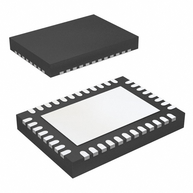


 工商网监
湘ICP备2023018690号
工商网监
湘ICP备2023018690号
