FEBFHR1200-SPG01A-GEVB 数据手册
User Guide for
FEBFHR1200_SPG01A
Evaluation Board
High-Performance Shunt Regulator
Featured Fairchild Product:
FHR1200
Direct questions or comments
about this evaluation board to:
“Worldwide Direct Support”
Fairchild Semiconductor.com
© 2014 Fairchild Semiconductor Corporation
FEBFHR1200_SPG01A • Rev. 1.0.0
�Table of Contents
1. Introduction ............................................................................................................................................. 4
1.1. Description .................................................................................................................................... 4
1.2. Features ........................................................................................................................................ 5
2. Evaluation Board Specifications ............................................................................................................. 6
3. Application Circuit Details ..................................................................................................................... 10
3.1. Application #3: Energy Storage Capacitor Charger .................................................................... 10
3.2. Application #4: Voltage Regulator & Reference ......................................................................... 11
3.3. Application #5: 0 to 6 V Regulator .............................................................................................. 22
3.4. Application #6: VCC or Brownout Regulator ................................................................................ 24
4. Schematic ............................................................................................................................................. 26
5. Bill of Material ....................................................................................................................................... 27
6. Application Circuit Tests ....................................................................................................................... 29
7. Device Characteristic Data ................................................................................................................... 33
8. Revision History .................................................................................................................................... 39
List of Tables
Table 1.
Table 2.
Table 3.
Table 4.
Table 5.
Table 6.
Table 7.
Table 8.
Table 9.
VBE and VREF Values at 40 µA: Grounded Configuration..................................................... 13
Resistor Divider Values vs. Output Voltage: Grounded Configuration .................................... 14
Resistor Divider Values vs. Output Voltage: Grounded Configuration .................................... 15
Resistor Divider Values for Isolated Output Regulator ............................................................ 16
VBE & VREF Performance Over-Temperature: Grounded Configuration................................... 17
Simple, Low-Cost 0 to 6 V Regulator Resistor Values ............................................................ 22
Application #6: VCC or Brownout Regulator Resistor Values, LM431 Configured ................... 24
VREF Temp Stability vs. IZ -55°C to +150°C: Grounded Configuration .................................... 36
VREF Temperature Stability vs. IZ -40°C to +125°C: Grounded Configuration ......................... 36
© 2014 Fairchild Semiconductor Corporation
2
FEBFHR1200_SPG01A • Rev. 1.0.0
�List of Figures
Figure 1.
Figure 2.
Figure 3.
Figure 4.
Figure 5.
Figure 6.
Figure 7.
Figure 8.
Figure 9.
Figure 10.
Figure 11.
Figure 12.
Figure 13.
Figure 14.
Figure 15.
Figure 16.
Figure 17.
Figure 18.
Figure 19.
Figure 20.
Figure 21.
Figure 22.
Figure 23.
Figure 24.
Figure 25.
Figure 26.
Figure 27.
Figure 28.
Figure 29.
Figure 30.
Figure 31.
Figure 32.
Figure 33.
Figure 34.
Figure 35.
Figure 36.
Figure 37.
Figure 38.
Figure 39.
Figure 40.
Figure 41.
Figure 42.
Figure 43.
Figure 44.
Figure 45.
Figure 46.
Figure 47.
Evaluation Board Photograph (Enlarged) .................................................................................. 5
Evaluation Board Floor Plan ...................................................................................................... 6
Break-Away Part Adapters ........................................................................................................ 7
Energy Storage Capacitor Charger ........................................................................................... 7
Power Supply Voltage Regulator............................................................................................... 8
Low-Voltage Auxiliary Regulator ............................................................................................... 8
Low-Cost VCC or Brownout Regulator ....................................................................................... 9
Energy Storage Capacitor, Regulated High-Efficiency Charger ............................................. 10
Energy Storage Capacitor Charger, Circuit Operation ............................................................ 11
Application Circuit #4: Overall Schematic ............................................................................... 12
Application Circuit #4: Isolated Output, Grounded Output Regulator...................................... 12
Reference Temperature Stability at 200 µA & 1 mA: Grounded Configuration....................... 14
Isolated Output Regulator: 431 Configuration ......................................................................... 15
Non-Isolated Output Regulator: Grounded Configuration ....................................................... 16
Basic Concept of Primary-Side Regulator: Grounded Configuration ...................................... 17
Primary-Side Regulator Based on App #4: Grounded Configuration ...................................... 18
Concept of Floating Regulator Based on App #4 Circuit ......................................................... 18
Floating Regulator Using App #4 Circuit: Grounded Configuration......................................... 19
Concept for Programmable Power Zener: App #4 Circuit ....................................................... 19
Characterization of FHR1200 used as Zener .......................................................................... 20
FHR1200 Dynamic Impedance ............................................................................................... 20
Concept and Actual Voltage Reference Using App #4 Circuit ................................................ 21
How to Add the App #4 Module to an Existing Power Supply ................................................. 21
Simple, Low-Cost 0 to 6 V Regulator: Application Circuit #5 .................................................. 22
FHR1200 Thermal De-Rating .................................................................................................. 23
Application #5: 3.3 V Power Supply Thermal Calculation ....................................................... 23
Application #6: VCC or Brownout Regulator Design ................................................................. 24
Application #6: Brownout & Auxiliary Regulator: LM431 Configured ...................................... 25
Evaluation Board Schematics.................................................................................................. 26
Connecting the Evaluation Board for Test............................................................................... 29
Break-Away Detail for Socket Adapters .................................................................................. 29
Testing the FHR1200 Devices on the Socket Adapters .......................................................... 30
Test of the Energy Capacitor Charger Operation .................................................................... 30
Energy Capacitor Charger Circuit Operation Description ....................................................... 31
Voltage Regulator Circuit Checkout ........................................................................................ 31
3.3 V Low-Voltage Regulator Checkout .................................................................................. 32
VCC or Brownout Regulator Circuit Checkout .......................................................................... 32
Calculating the FHR1200 Reference Temperature Coefficient ............................................... 33
LM431 Configured Reference Temperature Stability .............................................................. 33
VREF; 10 µA, 25 µA IZ Temperature Stability: Grounded Configuration ................................... 34
VREF; 40 µA, 60 µA IZ Temperature Stability: Grounded Configuration ................................... 34
VBE; 10 µA, 25 µA IZ Temperature Stability: Grounded Configuration ..................................... 35
VBE; 40 µA, 60 µA IZ Temperature Stability: Grounded Configuration ..................................... 35
BJT hfe Variation Over Temperature ...................................................................................... 37
Zener Voltage vs. IZ vs. Temperature...................................................................................... 37
Zener Temperature Coefficient Change Over Temperature ................................................... 38
FHR1200 Small-Signal Response ........................................................................................... 38
© 2014 Fairchild Semiconductor Corporation
3
FEBFHR1200_SPG01A • Rev. 1.0.0
�This user guide supports four applications for the FHR1200. It should be used in
conjunction with the FHR1200 datasheet as well as Fairchild’s application notes and
technical support team. Please visit Fairchild’s website at www.fairchildsemi.com.
1.
Introduction
This document describes four proposed applications for the FHR1200 high-performance
shunt regulator. These include:
A. Two each SC70-to-DIP adapters: The small size of the SC70 can make it difficult to
solder to the part for prototyping. Each adapter is supplied with a FHR1200 already
soldered down.
B. A 3.3 V-to-12 V regulated energy-storage-capacitor charger. Some smart meters only
consume around 250 mW 99% of the time so can use a single 3.3 V low-power offline
supply. However, to transmit, they require much higher power for a few milliseconds and
can pull this voltage from a storage capacitor charged to a higher voltage.
C. Voltage regulator and reference: This module can be used with most power supply
topologies and on isolated, non-isolated, primary-side, and floating applications.
D. Low-cost, low-voltage auxiliary regulator: Some designs need a regulated voltage in the
0 to 6 V range at just a few milliamps. The FHR1200 makes it possible to create a lowcost regulator for this application and can operate with an input voltage to >100 V.
E. Simple VCC or brownout regulator: Many power supply designs require that the VCC
voltage be regulated for the controller. The low operating current, high voltage and wide
temperature range make the FHR1200 a good choice for general regulation applications.
This document contains a general description of the FHR1200, the specifications for each
application circuit, schematics, bill of materials, and the typical operating characteristics.
1.1. Description
The FHR1200 is a high-efficiency regulator that outperforms a typical shunt regulator in
applications where low operating power, wide temperature range, and wide voltage range
are important. The regulator also features better stability and faster response than many
existing regulators.
The FHR1200 can be used for isolated and non-isolated secondary side regulation plus,
primary side, and floating regulation because the regulator can directly drive a power
supply controller. This reduces parts count and circuit complexity in many applications.
Non-isolated secondary-side regulation saves the cost of OPTOs and simplifies the power
supply design.
The FHR1200 can be used in many diverse applications. For example: VCC regulators to
>100 V, small additional auxiliary power supplies, programmable precision Zener diodes
(both high and low power), plus numerous analog circuits.
The FHR1200 can also be used as a standalone, low-cost, thermally stable, ~7.5 V
voltage reference.
© 2014 Fairchild Semiconductor Corporation
4
FEBFHR1200_SPG01A • Rev. 1.0.0
�1.2. Features
Low Current Operation: 100 V
Fewest External Component Count
Temperature Compensated: Typical
FEBFHR1200-SPG01A-GEVB 价格&库存
很抱歉,暂时无法提供与“FEBFHR1200-SPG01A-GEVB”相匹配的价格&库存,您可以联系我们找货
免费人工找货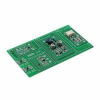


 工商网监
湘ICP备2023018690号
工商网监
湘ICP备2023018690号
