NB3W1900L
3.3 V 100/133 MHz
Differential 1:19
HCSL-Compatible Push‐Pull
Clock ZDB/Fanout Buffer for
PCIe[
www.onsemi.com
Description
The NB3W1900L differential clock buffers are designed to work in
conjunction with a PCIe compliant source clock synthesizer to provide
point-to-point clocks to multiple agents. The device is capable of
distributing the reference clocks for Intel® QuickPath Interconnect
(Intel QPI & UPI), PCIe Gen1/Gen2/Gen3/Gen4.The NB3W1900L
internal PLL is optimized to support 100�MHz and 133 MHz
frequency operation. The NB3W1900L is developed with the
low-power NMOS Push-Pull buffer type.
Features
•
•
•
•
•
•
•
•
•
•
•
•
•
•
•
January, 2018 − Rev. 3
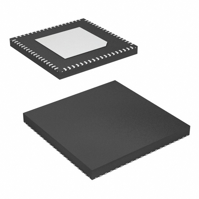
QFN72
MN SUFFIX
CASE 485DK
MARKING DIAGRAM
1
19 Low Power Differential Clock Output Pairs @ 0.7 V
Output-to-Output Skew Performance: < 85 ps
Cycle-to-Cycle Jitter (PLL Mode): < 50ps
100 MHz and 133 MHz PLL Mode to Meet the Next Generation
PCIe Gen2/Gen3/Gen4 and Intel QPI & UPI Phase Jitter
Input-to-Output Delay Variation: < 50 ps
Fixed-Feedback for Lowest Input-to-Output Delay Variation
Spread Spectrum Compatible; Tracks Input Clock Spreading for Low
EMI
Individual OE Control via SMBus
Low-Power NMOS Push-Pull HCSL−Compatible Outputs
PLL Configurable for PLL Mode or Bypass Mode
(Fanout Operation)
SMBus Address Configurable to Allow Multiple Buffers in a Single
Control Network
Programmable PLL Bandwidth
Two Tri-level Addresses Selection (Nine SMBus Addresses)
QFN 72-pin Package, 10 mm × 10 mm
These are Pb-Free Devices
© Semiconductor Components Industries, LLC, 2017
1 72
1
NB3W
1900L
AWLYYWWG
A
WL
YY
WW
G
= Assembly Location
= Wafer Lot
= Year
= Work Week
= Pb-Free Package
ORDERING INFORMATION
See detailed ordering and shipping information on page 19 of
this data sheet.
Publication Order Number:
NB3W1900L/D
�NB3W1900L
FBOUT_NC
FBOUT_NC#
SSC Compatible
PLL
CLK_IN
DIF[18:0]
MUX
DIF[18:0]#
CLK_IN#
100M_133M#
HBW_BYP_LBW#
SA_0
Control
Logic
SA_1
PWRGD/PWRDN#
SDA
SCL
DIF13#
DIF13
VDDIO
GND
DIF14
DIF14#
DIF15
DIF15#
GND
VDD
DIF16
DIF16#
DIF17
DIF17#
VDDIO
55
GND
72 71 70 69 68 67 66 65 64 63 62 61 60 59 58 57 56
DIF18
DIF18#
Figure 1. Simplified Block Diagram
VDDA
1
54
DIF12#
GNDA
2
53
DIF12
100M_133M#
3
52
VDDIO
HBW_BYP_LBW#
4
51
GND
PWRGD/PWRDN#
5
50
DIF11#
GND
6
49
DIF11
VDDR
7
48
DIF10#
CLK_IN
8
47
DIF10
CLK_IN#
9
46
GND
SA_0
10
45
VDD
SDA
11
44
DIF9#
SCL
12
43
DIF9
SA_1
13
42
DIF8#
FBOUT_NC#
14
41
DIF8
FBOUT_NC
15
40
VDDIO
GND
16
39
GND
DIF0
17
38
DIF7#
DIF0#
18
37
DIF7
NB3W1900L
Figure 2. Pin Configuration
(Top View)
www.onsemi.com
2
DIF6#
DIF6
GND
VDDIO
DIF5#
DIF5
DIF4#
DIF4
VDD
GND
DIF3#
DIF3
DIF2#
DIF2
GND
VDDIO
DIF1
DIF1#
19 20 21 22 23 24 25 26 27 28 29 30 31 32 33 34 35 36
�NB3W1900L
Table 1. POWER DOWN PIN TABLE
Inputs
Control Bits
Outputs
CLK_IN /
CLK_IN#
SMBus
EN Bit
DIFx / DIFx#
FBOUT_NC /
FBOUT_NC#
PLL Stage
0
X
X
Low/Low
Low/Low
OFF
1
Running
0
Low/Low
Running
ON
1
Running
Running
ON
PWRGD/PWRDN#
Table 2. POWER CONNECTIONS
Pin Number
VDD
VDDIO
VDDR
GND
Description
7
6
Analog Input
2
Analog PLL
16, 22, 27, 34, 39, 46, 51, 58, 63, 70
DIF clocks
1
28, 45, 64
21, 33, 40, 52, 57, 69
Table 3. TRI-LEVEL INPUT THRESHOLDS
Table 5. PLL OPERATING MODE
Level
Voltage
HBW_BYP_LBW#
MODE
Low
< 0.8 V
Low
PLL Lo BW
Mid
1.2 < Vin < 1.8 V
Mid
Bypass
High
Vin > 2.2 V
High
PLL Hi BW
NOTE:
PLL is OFF in Bypass
Table 4. FUNCTIONALITY AT POWER-UP (PLL Mode)
Table 6. MODE TRI−LEVEL INPUT THRESHOLD
CLK_IN
DIFx
100M_133M#
MHz
MHz
Level
Voltage
1
100.00
CLK_IN
Low
< 0.8 V
0
133.33
CLK_IN
Mid
1.2 < Vin < 1.8 V
High
Vin > 2.2 V
www.onsemi.com
3
�NB3W1900L
Table 7. NB3W1900L PIN DESCRIPTIONS
Pin Number
Pin Name
Type
1
VDDA
PWR
3.3 V Power Supply for PLL core.
2
GNDA
GND
Ground for PLL core.
3
100M_133M#
IN
Input to select operating frequency.
See functionality table for definition.
4
HBW_BYP_LBW#
IN
Tri-level input to select High BW, Bypass or low BW mode.
See PLL operating mode table for definition.
5
PWRGD/PWRDN#
IN
Notifies device to sample latched inputs and start up on first high assertion, or exit
power down mode on subsequent assertions. Low enters power down mode.
6
GND
GND
Ground pin
7
VDDR
PWR
3.3 V power for differential input clock (receiver). This VDD should be treated as an
analog power rail and filtered appropriately.
8
CLK_IN
IN
0.7 V differential true input
Description
9
CLK_IN#
IN
0.7 V differential complementary input
10
SA_0
IN
SMBus address bit. This is a tri-level input that works in conjunction with the SA_1
to decode 1 of 9 SMBus addresses.
11
SDA
I/O
Data pin of SMBus circuitry, 5 V tolerant
12
SCL
IN
Clock pin of SMBus circuitry, 5 V tolerant
13
SA_1
IN
SMBus address bit. This is a tri-level input that works in conjunction with the SA_0
to decode 1 of 9 SMBus addresses.
14
FBOUT_NC#
OUT
Complementary half of differential feedback output. This pin should NOT be
connected to anything outside the chip. It exists to provide delay path matching to
get 0 ps propagation delay.
15
FBOUT_NC
OUT
True half of differential feedback output. This pin should NOT be connected to
anything outside the chip. It exists to provide delay path matching to get 0
propagation delay.
16
GND
GND
Ground pin
17
DIF0
OUT
0.7 V differential true clock output
18
DIF0#
OUT
0.7 V differential complementary clock output
19
DIF1
OUT
0.7 V differential true clock output
20
DIF1#
OUT
0.7 V differential complementary clock output
21
VDDIO
PWR
Power supply for differential outputs
22
GND
GND
Ground pin
23
DIF2
OUT
0.7 V differential true clock output
24
DIF2#
OUT
0.7 V differential complementary clock output
25
DIF3
OUT
0.7 V differential true clock output
26
DIF3#
OUT
0.7 V differential complementary clock output
27
GND
GND
Ground pin
28
VDD
PWR
Power supply nominal 3.3 V
29
DIF4
OUT
0.7 V differential true clock output
30
DIF4#
OUT
0.7 V differential complementary clock output
31
DIF5
OUT
0.7 V differential true clock output
32
DIF5#
OUT
0.7 V differential complementary clock output
33
VDDIO
PWR
Power supply for differential outputs
34
GND
GND
Ground pin
35
DIF6
OUT
0.7 V differential true clock output
1. All VDD, VDDR, VDDIO,VDDA and GND pins must be externally connected to a power supply for proper operation.
www.onsemi.com
4
�NB3W1900L
Table 7. NB3W1900L PIN DESCRIPTIONS (continued)
Pin Number
Pin Name
Type
Description
36
DIF6#
OUT
0.7 V differential complementary clock output
37
DIF7
OUT
0.7 V differential true clock output
38
DIF7#
OUT
0.7 V differential complementary clock output
39
GND
GND
Ground pin
40
VDDIO
PWR
Power supply for differential outputs
41
DIF8
OUT
0.7 V differential true clock output
42
DIF8#
OUT
0.7 V differential complementary clock output
43
DIF9
OUT
0.7 V differential true clock output
44
DIF9#
OUT
0.7 V differential complementary clock output
45
VDD
PWR
Power supply nominal 3.3 V
46
GND
GND
Ground pin
47
DIF10
OUT
0.7 V differential true clock output
48
DIF10#
OUT
0.7 V differential complementary clock output
49
DIF11
OUT
0.7 V differential true clock output
50
DIF11#
OUT
0.7 V differential complementary clock output
51
GND
GND
Ground pin
52
VDDIO
PWR
Power supply for differential outputs
53
DIF12
OUT
0.7 V differential true clock output
54
DIF12#
OUT
0.7 V differential complementary clock output
55
DIF13
OUT
0.7 V differential true clock output
56
DIF13#
OUT
0.7 V differential complementary clock output
57
VDDIO
PWR
Power supply for differential outputs
58
GND
GND
Ground pin
59
DIF14
OUT
0.7 V differential true clock output
60
DIF14#
OUT
0.7 V differential complementary clock output
61
DIF15
OUT
0.7 V differential true clock output
62
DIF15#
OUT
0.7 V differential complementary clock output
63
GND
GND
Ground pin
64
VDD
PWR
Power supply nominal 3.3 V
65
DIF16
OUT
0.7 V differential true clock output
66
DIF16#
OUT
0.7 V differential complementary clock output
67
DIF17
OUT
0.7 V differential true clock output
68
DIF17#
OUT
0.7 V differential complementary clock output
69
VDDIO
PWR
Power supply for differential outputs
70
GND
GND
Ground pin
71
DIF18
OUT
0.7 V differential true clock output
72
DIF18#
OUT
0.7 V differential complementary clock output
EP
Exposed Pad
Thermal
The Exposed Pad (EP) on the QFN-72 package bottom is thermally connected to
the die for improved heat transfer out of package. The exposed pad must be
attached to a heat-sinking conduit. The pad is electrically connected to the die, and
must be electrically and thermally connected to GND on the PC board.
1. All VDD, VDDR, VDDIO,VDDA and GND pins must be externally connected to a power supply for proper operation.
www.onsemi.com
5
�NB3W1900L
Table 8. ABSOLUTE MAXIMUM RATINGS (Note 2)
Symbol
Max
Unit
VDD / VDDA /
VDDR
3.3 V Core Supply Voltage (Note 3)
Parameter
Conditions
Min
Typ
4.6
V
VDD / VDDIO
3.3 V Logic and Output Supply Voltage
(Note 3)
4.6
V
VIH
Input High Voltage
Except for SMBus Interface
VDD +
0.5
V
VIH
VIHSMB
SMBus Clock and Data Pins
5.5
V
VIL
Input Low Voltage
GND −
0.5
−
V
Ts
Storage Temperature
−65
150
°C
TJ
Junction Temperature
125
°C
ESD prot.
ESD Protection (Human Body)
Human Body Model
qJA
Thermal Resistance Junction−to−Ambient
qJC
Thermal Resistance Junction−to−Case
V
2000
Still air
18.1
°C/W
5.0
°C/W
Stresses exceeding those listed in the Maximum Ratings table may damage the device. If any of these limits are exceeded, device functionality
should not be assumed, damage may occur and reliability may be affected.
2. Guaranteed by design and characterization, not tested in production.
3. Operation under these conditions is neither implied nor guaranteed.
Table 9. ELECTRICAL CHARACTERISTICS − CLOCK INPUT PARAMETERS
(TA = 0°C − 70°C; Supply Voltage VDD/VDDA = 3.3 V ±5%, VDDIO = 1.05 to 3.3 V ±5%. See Test Loads for Loading Conditions) (Note 4)
Parameter
Symbol
Conditions
Min
Typ
Max
Unit
VIHDIF
Input High Voltage − CLK_IN
Differential Inputs
(single-ended measurement)
600
1150
mV
VILDIF
Input Low Voltage − CLK_IN
Differential Inputs
(single-ended measurement)
VSS − 300
300
mV
VCOM
Input Common Mode
Voltage − CLK_IN (not spec’d)
Common Mode Input Voltage
300
1000
mV
Peak to Peak Value
300
1450
mV
Input Slew Rate − CLK_IN (Note 5)
Measured Differentially
0.4
8
V/ns
IIN
Input Leakage Current
VIN = VDD, VIN = GND
−5
5
mA
dtin
Input Duty Cycle
Measurement from Differential
Waveform
45
55
%
Differential Measurement
0
125
ps
VSWING
dv/dt
JDIFIn
Input Amplitude − CLK_IN not spec’d
Input Jitter − Cycle to Cycle
Product parametric performance is indicated in the Electrical Characteristics for the listed test conditions, unless otherwise noted. Product
performance may not be indicated by the Electrical Characteristics if operated under different conditions.
4. Guaranteed by design and characterization, not tested in production.
5. Slew rate measured through ±75 mV window centered around differential zero
Table 10. ELECTRICAL CHARACTERISTICS−INPUT/SUPPLY/COMMON OUTPUT PARAMETERS
(TA = 0°C − 70°C; Supply Voltage VDD/VDDA = 3.3 V ±5%, VDDIO = 1.05 V to 3.3 V ±5%. See Test Loads for Loading Conditions) (Note 6)
Symbol
Parameter
Conditions
Min
Typ
Max
Unit
VIH
Input High Voltage
Single-ended inputs, except SMBus, low
threshold and tri-level inputs
2
VDD + 0.3
V
VIL
Input Low Voltage
Single-ended inputs, except SMBus, low
threshold and tri−level inputs
GND − 0.3
0.8
V
IIN
Input Current
Single-ended inputs, VIN = GND,
VIN = VDD
−5
5
mA
VIH_FS
Input High Voltage
(Note 7)
0.7
VDD + 0.3
V
VIL_FS
Input Low Voltage
(Note 7)
GND − 0.3
0.35
V
www.onsemi.com
6
�NB3W1900L
Table 10. ELECTRICAL CHARACTERISTICS−INPUT/SUPPLY/COMMON OUTPUT PARAMETERS (continued)
(TA = 0°C − 70°C; Supply Voltage VDD/VDDA = 3.3 V ±5%, VDDIO = 1.05 V to 3.3 V ±5%. See Test Loads for Loading Conditions) (Note 6)
Symbol
Conditions
Min
VDD = 3.3 V, Bypass mode (Note 8)
33
Fipll
VDD = 3.3 V, 100.00 MHz PLL mode (Note 8)
99
Fipll
VDD = 3.3 V, 133.33 MHz PLL mode (Note 8)
132.33
Fibyp
Parameter
Input Frequency
Lpin
Pin Inductance
CIN
Capacitance
Typ
Max
Unit
150
MHz
100.00
101
MHz
133.33
134.33
MHz
7
nH
Logic Inputs, except CLK_IN
1.5
5
pF
CINCLK_IN
CLK_IN differential clock inputs (Note 10)
1.5
2.7
pF
COUT
Output pin capacitance
6
pF
From VDD Power-Up and after input clock
stabilization or de-assertion of PD# to
1st clock
1
ms
TSTAB
Clk Stabilization (Note 8)
fMODIN
Input SS Modulation Frequency
tLATOE#
OE# Latency
tDRVPD
Tdrive_PD# (Note 9)
Allowable Frequency
(Triangular Modulation)
30
33
kHz
DIF start after OE# assertion DIF stop
after OE# de-assertion
4
12
clocks
DIF output enable after
PD# de-assertion
300
ms
5
ns
tF
Tfall (Note 8)
Fall time of control inputs
tR
Trise (Note 8)
Rise time of control inputs
VILSMB
SMBus Input Low Voltage
VIHSMB
SMBus Input High Voltage
VOLSMB
SMBus Output Low Voltage
2.1
@ IPULLUP
IPULLUP
SMBus Sink Current
@ VOL
4
VDDSMB
Nominal Bus Voltage
3 V to 5 V ±10%
2.7
tRSMB
SCL/SDA Rise Time
tFSMB
SCL/SDA Fall Time
fMAXSMB
SMBus Operating Frequency
(Note 11)
5
ns
0.8
V
VDDSMB
V
0.4
V
mA
5.5
V
(Max VIL − 0.15) to (Min VIH + 0.15)
1000
ns
(Min VIH + 0.15) to (Max VIL − 0.15)
300
ns
Maximum SMBus operating frequency
100
kHz
Product parametric performance is indicated in the Electrical Characteristics for the listed test conditions, unless otherwise noted. Product
performance may not be indicated by the Electrical Characteristics if operated under different conditions.
6. Guaranteed by design and characterization, not tested in production.
7. 100M_133M# Frequency Select (FS).
8. Control input must be monotonic from 20% to 80% of input swing.
9. Time from de-assertion until outputs are > 200 mV
10. CLK_IN input
11. The differential input clock must be running for the SMBus to be active
www.onsemi.com
7
�NB3W1900L
Table 11. ELECTRICAL CHARACTERISTICS − DIF 0.7 V LOW POWER DIFFERENTIAL OUTPUTS
(TA = 0°C − 70°C; Supply Voltage VDD/VDDA = 3.3 V ±5%, VDDIO = 1.05 V to 3.3 V ±5%. See Test Loads for Loading Conditions)
(Note 12)
Parameter
Symbol
dV/dt
DdV/dt
Slew Rate (Notes 13, 14)
Conditions
Min
Scope averaging on
Typ
Max
Unit
1
4
V/ns
Slew Rate Matching (Notes 13, 15)
Slew rate matching, Scope averaging on
20
%
VHigh
Voltage High
660
850
mV
VLow
Voltage Low
Statistical measurement on single-ended
signal using oscilloscope math function.
(Scope averaging on)
−150
150
Vmax
Max Voltage
Vmin
Min Voltage
Measurement on single ended signal using
Absolute value. (Scope averaging off)
−300
Vswing (Note 13)
Scope averaging off
300
Vcross_abs
Crossing Voltage (abs) (Note 16)
Scope averaging off
250
DVcross
Crossing Voltage (var) (Note 17)
Scope averaging off
Vswing
1150
mV
mV
550
mV
140
mV
Product parametric performance is indicated in the Electrical Characteristics for the listed test conditions, unless otherwise noted. Product
performance may not be indicated by the Electrical Characteristics if operated under different conditions.
12. Guaranteed by design and characterization, not tested in production. CL = 2 pF with RS = 33 W for Zo = 50 W (100 W differential trace
impedance).
13. Measured from differential waveform
14. Slew rate is measured through the Vswing voltage range centered around differential 0 V. This results in a ±150 mV window around differential
0 V.
15. Matching applies to rising edge rate for Clock and falling edge rate for Clock#. It is measured using a ±75 mV window centered on the average
cross point where Clock rising meets Clock# falling. The median cross point is used to calculate the voltage thresholds the oscilloscope is
to use for the edge rate calculations.
16. Vcross is defined as voltage where Clock = Clock# measured on a component test board and only applies to the differential rising edge
(i.e. Clock rising and Clock# falling).
17. The total variation of all Vcross measurements in any particular system. Note that this is a subset of Vcross_min/max (Vcross absolute) allowed.
The intent is to limit Vcross induced modulation by setting DVcross to be smaller than Vcross absolute.
www.onsemi.com
8
�NB3W1900L
Table 12. ELECTRICAL CHARACTERISTICS − CURRENT CONSUMPTION
(TA = 0°C − 70°C; Supply Voltage VDD/VDDA = 3.3 V ±5%, VDDIO = 1.05 V to 3.3 V ±5%. See Test Loads for Loading Conditions) (Note 18)
Max
Unit
All outputs @ 100.00 MHz, CL = 2 pF; Zo = 85 W
50
mA
IDDVDDA/R
All outputs @ 100.00 MHz, CL = 2 pF; Zo = 85 W
30
mA
IDDVDDIO
All outputs @ 100.00 MHz, CL = 2 pF; Zo = 85 W
200
mA
All differential pairs low/low
4
mA
Symbol
IDDVDD
IDDVDDPD
Parameter
Operating Supply Current
Powerdown Current (Note 19)
Conditions
Min
Typ
IDDVDDA/RPD
All differential pairs low/low
5
mA
IDDVDDIOPD
All differential pairs low/low
0.2
mA
Product parametric performance is indicated in the Electrical Characteristics for the listed test conditions, unless otherwise noted. Product
performance may not be indicated by the Electrical Characteristics if operated under different conditions.
18. Guaranteed by design and characterization, not tested in production.
19. With input clock running. Stopping the input clock will result in lower numbers.
Table 13. ELECTRICAL CHARACTERISTICS − SKEW AND DIFFERENTIAL JITTER PARAMETERS
(TA = 0°C − 70°C; Supply Voltage VDD/VDDA = 3.3 V ±5%, VDDIO = 1.05 to 3.3 V ±5%. See Test Loads for Loading Conditions)
Symbol
Parameter
Conditions
Min
Typ
Max
Unit
tSPO_PLL
CLK_IN, DIF[x:0]
(Notes 20, 21, 23, 24 and 27)
Input-to-Output Skew in PLL mode nominal
value @ 25°C, 3.3 V
−100
100
ps
tPD_BYP
CLK_IN, DIF[x:0]
(Notes 20, 21, 22, 24 and 27)
Input-to-Output Skew in Bypass mode
nominal value @ 25°C, 3.3 V
2.5
4.5
ns
tDSPO_PLL
CLK_IN, DIF[x:0]
(Notes 20, 21, 22, 24 and 27)
Input-to-Output Skew Variation in PLL mode
across voltage and temperature
|100|
ps
tDSPO_BYP
CLK_IN, DIF[x:0]
(Notes 20, 21, 22, 24 and 27)
Input-to-Output Skew Variation in Bypass
mode across voltage and temperature
250
ps
tDTE
CLK_IN, DIF[x:0]
(Notes 20, 21, 22, 24 and 27)
Random Differential Tracking error between
two NB3W1900L devices in Hi BW Mode
5
ps
(rms)
tDSSTE
CLK_IN, DIF[x:0]
(Notes 20, 21, 22, 24 and 27)
Random Differential Spread Spectrum
Tracking error between two NB3W1900L
devices in Hi BW Mode.
75
ps
DIF[x:0]
(Notes 20, 21, 22 and 27)
Output-to-Output Skew across all outputs
(Common to Bypass and PLL mode)
85
ps
tSKEW_ALL
−250
jpeak-hibw
PLL Jitter Peaking
(Notes 26 and 27)
HBW_BYP_LBW# = 1
0
2.5
dB
jpeak-lobw
PLL Jitter Peaking
(Notes 26 and 27)
HBW_BYP_LBW# = 0
0
2
dB
pllHIBW
PLL Bandwidth (Notes 27 and 28)
HBW_BYP_LBW# = 1
2
4
MHz
pllLOBW
PLL Bandwidth (Notes 27 and 28)
HBW_BYP_LBW# = 0
0.7
1.4
MHz
tDC
Duty Cycle (Note 20)
Measured differentially, PLL Mode
45
50
55
%
tDCD
Duty Cycle Distortion
(Notes 20 and 29)
Measured differentially, Bypass Mode
@ 100.00 MHz
−2
0
2
%
tjcyc-cyc
Jitter, Cycle-to-Cycle
(Notes 20 and 30)
PLL mode
50
ps
Additive Jitter in Bypass Mode
50
ps
Product parametric performance is indicated in the Electrical Characteristics for the listed test conditions, unless otherwise noted. Product
performance may not be indicated by the Electrical Characteristics if operated under different conditions.
20. Measured into fixed 2 pF load cap. Input to output skew is measured at the first output edge following the corresponding input.
21. Measured from differential cross-point to differential cross-point. This parameter can be tuned with external feedback path, if present.
22. All Bypass Mode Input-to-Output specs refer to the timing between an input edge and the specific output edge created by it.
23. This parameter is deterministic for a given device
24. Measured with scope averaging on to find mean value.
25. t is the period of the input clock
26. Measured as maximum pass band gain. At frequencies within the loop BW, highest point of magnification is called PLL jitter peaking.
27. Guaranteed by design and characterization, not tested in production.
28. Measured at 3 db down or half power point.
29. Duty cycle distortion is the difference in duty cycle between the output and the input clock when the device is operated in bypass mode.
30. Measured from differential waveform
www.onsemi.com
9
�NB3W1900L
Table 14. ELECTRICAL CHARACTERISTICS − PHASE JITTER PARAMETERS
(TA = 0°C − 70°C; Supply Voltage VDD/VDDA = 3.3 V ±5%, VDDIO = 1.05 V to 3.3 V ±5%. See Test Loads for Loading Conditions) (Note 31)
Typ
Max
Unit
PCIe Gen 1 (Notes 32 and 33)
11
86
ps (p−p)
PCIe Gen 2 Lo Band 10 kHz < f < 1.5 MHz (Note 32)
0.2
3
ps (rms)
PCIe Gen 2 High Band 1.5 MHz < f < Nyquist (50 MHz)
(Note 32)
1.0
3.1
ps (rms)
tjphPCIeG3
PCIe Gen 3
(PLL BW of 2−4 MHz, CDR = 10 MHz)
(Notes 32, 33 and 34)
0.28
1
ps (rms)
tjphPCIeG4
PCIe Gen 4
(PLL BW of 2−4 MHz, CDR = 10 MHz)
0.28
0.5
ps (rms)
tjphUPI
UPI
(9.6 Gb/s, 10.4 Gb/s or 11.2 Gb/s, 100 MHz, 12 UI)
0.73
1.0
ps (rms)
tjphQPI_SMI
QPI & SMI
(100.00 MHz or 133.33 MHz, 4.8 Gb/s, 6.4 Gb/s 12UI)
(Note 35)
0.3
0.5
ps (rms)
QPI & SMI (100.00 MHz, 8.0 Gb/s, 12UI) (Note 35)
0.1
0.3
ps (rms)
QPI & SMI (100.00 MHz, 9.6 Gb/s, 12UI) (Note 35)
0.08
0.2
ps (rms)
PCIe Gen 1 (Notes 32 and 33)
10
ps (p−p)
PCIe Gen 2 Lo Band 10 kHz < f < 1.5 MHz
(Notes 32 and 36)
0.3
ps (rms)
PCIe Gen 2 High Band 1.5 MHz < f < Nyquist (50 MHz)
(Notes 32 and 36)
0.7
ps (rms)
tjphPCIeG3
PCIe Gen 3
(PLL BW of 2−4 MHz, CDR = 10 MHz)
(Notes 32, 34 and 36)
0.3
ps (rms)
tjphQPI_SMI
QPI & SMI
(100.00 MHz or 133.33 MHz, 4.8 Gb/s, 6.4 Gb/s 12UI)
(Notes 35 and 36)
0.3
ps (rms)
QPI & SMI (100.00 MHz, 8.0 Gb/s, 12UI)
(Notes 35 and 36)
0.1
ps (rms)
QPI & SMI (100.00 MHz, 9.6 Gb/s, 12UI)
(Notes 35 and 36)
0.1
ps (rms)
Symbol
tjphPCIeG1
Parameter
Phase Jitter, PLL Mode
tjphPCIeG2
tjphPCIeG1
tjphPCIeG2
Additive Phase Jitter,
Bypass Mode
Conditions
Min
Product parametric performance is indicated in the Electrical Characteristics for the listed test conditions, unless otherwise noted. Product
performance may not be indicated by the Electrical Characteristics if operated under different conditions.
31. Applies to all outputs.
32. See http://www.pcisig.com for complete specs
33. Sample size of at least 100k cycles. This figures extrapolates to 108 ps pk-pk @ 1M cycles for a BER of 1−12.
34. Subject to final ratification by PCI SIG.
35. Calculated from Intel-supplied Clock Jitter Tool v 1.6.3
36. For RMS figures, additive jitter is calculated by solving the following equation: (Additive jitter)2 = (total jittter)2 − (input jitter)2
www.onsemi.com
10
�NB3W1900L
Table 15. CLOCK PERIODS-DIFFERENTIAL OUTPUTS WITH SPREAD SPECTRUM DISABLED
Measurement Window
1 Clock
1 ms
0.1 s
− ppm
−SSC
−c 2c jitter Short−Term Long-Term
Average
AbsPer
Average
Center
Min
Min
Min
SSC OFF Freq. MHz
DIF
1 ms
0.1s
0.1s
0 ppm
Period
Nominal
+ ppm Long−
Term Average
Max
1 Clock
+SSC
+c2c jitter
Short−Term
Abs Per
Average Max
Max
Unit
Notes
1 00.00
9.94900
9.99900
10 .0000 0
1 0.001 00
10.05100
ns
37,
38, 39
1 33.33
7.44925
7.49925
7.50000
7.50075
7.55 075
ns
37,
38, 40
37. Guaranteed by design and characterization, not tested in production.
38. All Long Term Accuracy specifications are guaranteed with the assumption that the input clock complies with CK420BQ/CK410B+ accuracy
requirements (±100 ppm). The NB3W1900L it self does not contribute to ppm error.
39. Driven by SRC out put of main clock, 100.00 MHz PLL Mode or Bypass mode.
40. Driven by CPU out put of main clock, 133.33 MHz PLL Mode or Bypass mode.
Table 16. CLOCK PERIODS-DIFFERENTIAL OUTPUTS WITH SPREAD SPECTRUM ENABLED
Measurement Window
1 Clock
1 ms
0.1s
0.1s
− ppm
−SSC
−c2c jitter Short−Term Long-Term
Average 0 ppm PeriAbsPer
Average
Center
od Nominal
Min
Min
Min
SSC ON Freq. MHz
DIF
1 ms
0.1s
+ ppm Long−
Term Average
Max
1 Clock
+SSC
+c2c jitter
Short−Term
AbsPer
Average Max
Max
Unit
Notes
99.75
9.94906
9. 99906
10.02406
10.02506
10.02607
10.05107
10.10107
ns
41,
42, 43
133.00
7.44930
7. 49930
7.51805
7.51880
7.51955
7.53830
7.58830
ns
41,
42, 44
41. Guaranteed by design and characterization, not tested in production.
42. All Long Term Accuracy specifications are guaranteed with the assumption that the input clock complies with CK420BQ/ CK410B+ accuracy
requirements (±100 ppm). The NB3W1900L it self does not contribute to ppm error.
43. Driven by SRC out put of main clock, 100.00 MHz PLL Mode or Bypass mode.
44. Driven by CPU out put of main clock, 133.33 MHz PLL Mode or Bypass mode.
TEST LOADS
Differential Zo,
10 inches
Rs
Rs
LP−HCSL
Differential
Output
Figure 3. NB3W1900L Differential Test Loads
Table 17. DIFFERENTIAL OUTPUT TERMINATIONS
DIF Zo (W)
Rs (W)
100
33
85
27
www.onsemi.com
11
2pF
2pF
�NB3W1900L
PWRGD/PWRDN#
asserted low by two consecutive rising edges of DIF#, all
differential outputs are held tri−stated on the next DIF# high
to low transition. The assertion and de-assertion of
PWRDN# is absolutely asynchronous.
WARNING: Disabling of the CLK_IN input clock prior
to assertion of PWRDN# is an undefined
mode and not recommended. Operation in
this mode may result in glitches, excessive
frequency shifting, etc.
PWRGD/PWRDN# is a dual function pin. PWRGD is
asserted high and de−asserted low. De−assertion of PWRGD
(pulling the signal low) is equivalent to indicating a
powerdown condition. PWRGD (assertion) is used by the
NB3W1900L to sample initial configurations such as
frequency select condition and SA selections.
After PWRGD has been asserted high for the first time,
the pin becomes a PWRDN# (Power Down) pin that can be
used to shut off all clocks cleanly and instruct the device to
invoke power savings mode. PWRDN# is a completely
asynchronous active low input. When entering power
savings mode, PWRDN# should be asserted low prior to
shutting off the input clock or power to ensure all clocks
shut down in a glitch free manner. When PWRDN# is
Table 18. PWRGD/PWRDN# FUNCTIONALITY
PWRGD/PWRDN#
DIF
DIF#
0
Tri−state
Tri−state
1
Running
Running
www.onsemi.com
12
�NB3W1900L
Buffer Power−Up State Machine
Table 19. BUFFER POWER−UP STATE MACHINE
State
Description
0
3.3 V Buffer power off
1
After 3.3 V supply is detected to rise above 3.135 V, the buffer enters State 1 and initiates a 0.1 ms–0.3 ms delay.
2
Buffer waits for a valid clock on the CLK input and PWRDN# de−assertion (or PWRGD assertion low to high)
3
Once the PLL is locked to the CLK_IN input clock, the buffer enters state 3 and enables outputs for normal operation.
(Notes 45, 46)
45. The total power up latency from power on to all outputs active must be less than 1.8 ms (assuming a valid clock is present on CLK_IN input).
46. If power is valid and powerdown is de−asserted (PWRGD asserted) but no input clocks are present on the CLK_IN input, DIF clocks must
remain disabled. Only after valid input clocks are detected, valid power, PWRDN# de−asserted (PWRGD asserted) with the PLL
locked/stable and the DIF outputs enabled.
No input clock
State 1
State 2
Delay
0.1 ms − 0.3 ms
Wait for input
clock and
powerdown
de−assertion
Powerdown Asserted
State 0
State 3
Power Off
Normal
Operation
Figure 4. Buffer Power−Up State Diagram
Device Power−Up Sequence
3. Apply power to the device.
4. Once the VDD pin has reached a valid VDDmin
level (3.3V −5%), the PWRGD/PWRDN# pin
must be asserted High. See Figure 5.
Note: If no clock is present on the CLK_IN/CLK_IN#
pins when device is powered up, there will be no clock on
DIF/DIF# outputs.
Follow the power−up sequence below for proper device
functionality:
1. PWRGD/PWRDN# pin must be Low.
2. Assign remaining control pins to their required
state (100M_133M#, HBW_BYPASS_LBW#,
SDA, SCL)
Figure 5. PWRGD and VDD Relationship Diagram
www.onsemi.com
13
�NB3W1900L
GENERAL SMBus SERIAL INTERFACE INFORMATION
•
•
•
•
•
•
•
•
How to Write
•
•
•
•
•
•
•
•
•
•
Controller (host) sends a start bit
Controller (host) sends the write address
Clock (device) will acknowledge
Controller (host) sends the beginning byte location = N
Clock (device) will acknowledge
Controller (host) sends the byte count = X
Clock (device) will acknowledge
Controller (host) starts sending Byte N through Byte
N+X−1
Clock (device) will acknowledge each byte one at
a time
Controller (host) sends a Stop bit
•
•
•
Controller (host) sends the beginning byte location = N
Clock (device) will acknowledge
Controller (host) will send a separate start bit
Controller (host) sends the read address
Clock (device) will acknowledge
Clock (device) will send the data byte count = X
Clock (device) sends Byte N + X − 1
Clock (device) sends Byte 0 through Byte X
(if X(H) was written to Byte 8)
Controller (host) will need to acknowledge each byte
Controller (host) will send a not acknowledge bit
Controller (host) will send a stop bit
Table 21. INDEX BLOCK READ OPERATION
Table 20. INDEX BLOCK WRITE OPERATION
Controller (Host)
T
Controller (Host)
Clock (Device)
T
Clock (Device)
starT bit
starT bit
Slave Address
Slave Address
WR
WR
WRite
WRite
ACK
ACK
Beginning Byte = N
Beginning Byte = N
ACK
ACK
Data Byte Count = X
RT
ACK
Repeat starT
Slave Address
Beginning Byte N
RD
X Byte
ReaD
ACK
ACK
O
O
O
O
O
X Byte
Data Byte Count = X
ACK
Beginning Byte N
O
ACK
Byte N + X − 1
O
ACK
P
stoP bit
O
O
O
O
O
How to Read
Byte N + X − 1
• Controller (host) will send a start bit
• Controller (host) sends the write address
• Clock (device) will acknowledge
N
Not
acknowledge
P
stoP bit
www.onsemi.com
14
�NB3W1900L
Table 22. SMBus ADDRESSING
SA_1 and SA_0
SMBus 8-bit Address (Rd/Wrt bit = 0)
00
D8
0M
DA
01
DE
M0
C2
MM
C4
M1
C6
10
CA
1M
CC
11
CE
Table 23. SMBus Table: PLL MODE, AND FREQUENCY SELECT REGISTER
Byte 0
Pin #
Name
Control Function
Type
0
1
See PLL Operating Mode
Readback Table
Default
Bit 7
4
PLL Mode 1
PLL Operating Mode Rd back 1
R
Bit 6
4
PLL Mode 0
PLL Operating Mode Rd back 0
R
Bit 5
72/71
DIF_18_En
Output Control overrides OE# pin
RW
Low/Low
Enable
1
Bit 4
68/67
DIF_17_En
Output Control overrides OE# pin
RW
Low/Low
Enable
1
Bit 3
66/65
DIF_16_En
Output Control overrides OE# pin
RW
Low/Low
Enable
1
Bit 2
Reserved
Bit 1
Bit 0
100M_133M#
Frequency Select Readback
Latch
0
Reserved
3
Latch
0
R
133 MHz
100 MHz
Latch
0
1
Default
Table 24. SMBus TABLE: OUTPUT CONTROL REGISTER
Byte 1
Pin #
Name
Control Function
Type
Bit 7
38/37
DIF_7_En
Output Control overrides OE# pin
RW
1
Bit 6
35/36
DIF_6_En
Output Control overrides OE# pin
RW
1
Bit 5
31/32
DIF_5_En
Output Control overrides OE# pin
RW
1
Bit 4
29/30
DIF_4_En
Output Control overrides OE# pin
RW
1
Low/Low
Enable
Bit 3
25/26
DIF_3_En
Output Control overrides OE# pin
RW
1
Bit 2
23/24
DIF_2_En
Output Control overrides OE# pin
RW
1
Bit 1
19/20
DIF_1_En
Output Control overrides OE# pin
RW
1
Bit 0
17/18
DIF_0_En
Output Control overrides OE# pin
RW
1
Table 25. SMBus TABLE: OUTPUT CONTROL REGISTER
Byte 2
Pin #
Name
Control Function
Type
0
1
Default
Bit 7
62/61
DIF_15_En
Output Control overrides OE# pin
RW
1
Bit 6
60/59
DIF_14_En
Output Control overrides OE# pin
RW
1
Bit 5
56/55
DIF_13_En
Output Control overrides OE# pin
RW
1
Bit 4
54/53
DIF_12_En
Output Control overrides OE# pin
RW
1
Low/Low
Enable
Bit 3
50/49
DIF_11_En
Output Control overrides OE# pin
RW
Bit 2
48/47
DIF_10_En
Output Control overrides OE# pin
RW
1
Bit 1
44/43
DIF_9_En
Output Control overrides OE# pin
RW
1
Bit 0
42/41
DIF_8_En
Output Control overrides OE# pin
RW
1
www.onsemi.com
15
1
�NB3W1900L
Table 26. SMBus TABLE: RESERVED REGISTER
Byte 3
Pin #
Name
Control Function
Type
0
1
Default
Bit 7
Reserved
0
Bit 6
Reserved
0
Bit 5
Reserved
0
Bit 4
Reserved
0
Bit 3
Reserved
0
Bit 2
Reserved
0
Bit 1
Reserved
0
Bit 0
Reserved
0
Table 27. SMBus TABLE: RESERVED REGISTER
Byte 4
Pin #
Name
Control Function
Type
0
1
Default
Bit 7
Reserved
0
Bit 6
Reserved
0
Bit 5
Reserved
0
Bit 4
Reserved
0
Bit 3
Reserved
0
Bit 2
Reserved
0
Bit 1
Reserved
0
Bit 0
Reserved
0
Table 28. SMBus TABLE: VENDOR & REVISION ID REGISTER
Byte 5
Pin #
Name
Bit 7
−
RID3
Bit 6
−
RID2
Control Function
Type
0
1
Default
R
−
−
X
R
−
−
X
REVISION ID
Bit 5
−
RID1
R
−
−
X
Bit 4
−
RID0
R
−
−
X
Bit 3
−
VID3
R
−
−
1
Bit 2
−
VID2
R
−
−
1
VENDOR ID
Bit 1
−
VID1
R
−
−
1
Bit 0
−
VID0
R
−
−
1
Type
0
1
Default
Table 29. SMBus TABLE: DEVICE ID
Byte 6
Pin #
Bit 7
−
Name
Device ID 7 (MSB)
Control Function
R
1
Bit 6
−
Device ID 6
R
1
Bit 5
−
Device ID 5
R
0
Bit 4
−
Device ID 4
R
Bit 3
−
Device ID 3
R
Bit 2
−
Device ID 2
R
0
Bit 1
−
Device ID 1
R
1
Bit 0
−
Device ID 0
R
1
www.onsemi.com
16
Device ID is 130 decimal or
82 hex.
1
1
�NB3W1900L
Table 30. SMBus TABLE: BYTE COUNT REGISTER
Byte 7
Pin #
Name
Control Function
Type
0
1
Default
Bit 7
Reserved
0
Bit 6
Reserved
0
Bit 5
Reserved
0
Bit 4
−
BC4
Bit 3
−
BC3
RW
RW
Writing to this register configures how
many bytes will be read back.
Bit 2
−
BC2
Bit 1
−
BC1
RW
RW
Bit 0
−
BC0
RW
0
Default value is 8 hex, so 9
bytes (0 to 8) will be read
back by default.
1
0
0
0
Table 31. SMBus TABLE: RESERVED REGISTER
Byte 8
Pin #
Name
Control Function
Type
0
1
Default
Bit 7
Reserved
0
Bit 6
Reserved
0
Bit 5
Reserved
0
Bit 4
Reserved
0
Bit 3
Reserved
0
Bit 2
Reserved
0
Bit 1
Reserved
0
Bit 0
Reserved
0
Table 32. DIF REFERENCE CLOCK
Common R Recommendations for Differential Routing
Dimension or Value
Unit
L1 length, route as non-coupled 50 W trace (see Figure 6)
0.5 max
inch
L2 length, route as non-coupled 50 W trace (see Figure 6)
0.2 max
inch
L3 length, route as non-coupled 50 W trace (see Figure 6)
0.2 max
inch
Rs (100 W differential traces) (see Figure 6)
33
W
Rs (85 W differential traces) (see Figure 6)
27
W
2 min to 16 max
inch
1.8 min to 14.4 max
inch
0.25 to 14 max
inch
0.225 min to 12.6 max
inch
Down Device Differential Routing
L4 length, route as coupled micro strip 100 W differential trace (see Figure 6)
L4 length, route as coupled strip line 100 W differential trace (see Figure 6)
Differential Routing to PCI Express Connector
L4 length, route as coupled microstrip 100 W differential trace (see Figure 7)
L4 length, route as coupled stripline 100 W differential trace (see Figure 7)
www.onsemi.com
17
�NB3W1900L
L2
L1
Rs
L4
L4’
L2’
L1’
Rs
LP−HCSL
Differential Output
PCI Express
Down Device
REF_CLK Input
Figure 6. Down Device Routing
L2
L1
Rs
L4
L4’
L2’
L1’
Rs
LP−HCSL
Differential Output
PCI Express
Add−in Board
REF_CLK Input
Figure 7. PCI Express Connector Routing
Table 33. CABLE CONNECTED AC COUPLED APPLICATION (Figure 8)
Component
Value
R5a, R5b
8.2k 5%
R6a, R6b
1k 5%
Cc
0.1 mF
Vcm
0.350 V
Note
3.3 Volts
R5a
R5b
R6a
R6b
Cc
L4
L4’
Cc
Figure 8.
www.onsemi.com
18
�NB3W1900L
POWER FILTERING EXAMPLE
Ferrite Bead Power Filtering
Recommended ferrite bead filtering equivalent to the following:
600 Q impedance at 100.00 MHz, ≤ 0.1 Q DCR max., ≥ 400 mA current rating.
V3P3
Place at pin
FB1
R1
FERRITE
2.2
VDDA
C9
1 mF
R2
2.2
VDD for PLL
C7
0.1 mF
VDDR
C10
1 mF
VDD for Input Receiver
VDD_DIF
C8
0.1 mF
F C5
C5
0.1 mF
0.1 mF
C5
0.1 mF
C5
0.1 mF
VDDIO
C1
10 mF
C4
0.1 mF
C2
0.1 mF
C3
0.1 mF
Figure 9. Schematic Example of the NB3W1900L Power Filtering
Table 34. ORDERING INFORMATION
Package
Shipping†
NB3W1900LMNG
QFN−72
(Pb−Free)
168 Units / Tray
NB3W1900LMNTXG
QFN−72
(Pb−Free)
1,000 / Tape & Reel
Device
†For information on tape and reel specifications, including part orientation and tape sizes, please refer to our Tape and Reel Packaging
Specifications Brochure, BRD8011/D.
Intel is a registered trademark of Intel Corporation.
PCIe and PCI−SIG are registered trademarks of PCI−SIG.
www.onsemi.com
19
�MECHANICAL CASE OUTLINE
PACKAGE DIMENSIONS
QFN72 10x10, 0.5P
CASE 485DK
ISSUE O
DATE 12 NOV 2013
1 72
SCALE 1:1
PIN ONE
LOCATION
ÉÉÉ
ÉÉÉ
ÉÉÉ
A B
D
L
L1
DETAIL A
ALTERNATE
CONSTRUCTIONS
E
0.15 C
TOP VIEW
MOLD CMPD
DETAIL B
ALTERNATE
CONSTRUCTION
(A3)
DETAIL B
0.10 C
0.08 C
1
A1
C
SIDE VIEW
0.10
DETAIL A
M
D2
19
72X
36
SEATING
PLANE
XXXXXXXXX
XXXXXXXXX
AWLYYWWG
C A B
L
0.10
M
XXXXX = Specific Device Code
A
= Assembly Location
WL
= Wafer Lot
YY
= Year
WW
= Work Week
G
= Pb−Free Package
*This information is generic. Please refer
to device data sheet for actual part
marking.
Pb−Free indicator, “G” or microdot “ G”,
may or may not be present.
C A B
E2
1
72
55
e
BOTTOM VIEW
MILLIMETERS
MIN
MAX
0.80
1.00
0.00
0.05
0.20 REF
0.18
0.30
10.00 BSC
5.85
6.15
10.00 BSC
5.85
6.15
0.50 BSC
0.30
0.50
0.00
0.15
GENERIC
MARKING DIAGRAM*
A
NOTE 4
DIM
A
A1
A3
b
D
D2
E
E2
e
L
L1
ÉÉÉ
ÉÉÉ
EXPOSED Cu
0.15 C
L
NOTES:
1. DIMENSIONING AND TOLERANCING PER
ASME Y14.5M, 1994.
2. CONTROLLING DIMENSIONS: MILLIMETERS.
3. DIMENSION b APPLIES TO PLATED
TERMINAL AND IS MEASURED BETWEEN
0.15 AND 0.25mm FROM THE TERMINAL TIP.
4. COPLANARITY APPLIES TO THE EXPOSED
PAD AS WELL AS THE TERMINALS.
72X
b
0.10
0.05
M
M
C A B
C NOTE 3
RECOMMENDED
SOLDERING FOOTPRINT
10.30
6.25
72X
0.63
1
6.25
PKG
OUTLINE
DOCUMENT NUMBER:
DESCRIPTION:
98AON79920F
QFN72 10x10, 0.5P
0.50
PITCH
10.30
72X
0.32
DIMENSIONS: MILLIMETERS
Electronic versions are uncontrolled except when accessed directly from the Document Repository.
Printed versions are uncontrolled except when stamped “CONTROLLED COPY” in red.
PAGE 1 OF 1
ON Semiconductor and
are trademarks of Semiconductor Components Industries, LLC dba ON Semiconductor or its subsidiaries in the United States and/or other countries.
ON Semiconductor reserves the right to make changes without further notice to any products herein. ON Semiconductor makes no warranty, representation or guarantee regarding
the suitability of its products for any particular purpose, nor does ON Semiconductor assume any liability arising out of the application or use of any product or circuit, and specifically
disclaims any and all liability, including without limitation special, consequential or incidental damages. ON Semiconductor does not convey any license under its patent rights nor the
rights of others.
© Semiconductor Components Industries, LLC, 2019
www.onsemi.com
�onsemi,
, and other names, marks, and brands are registered and/or common law trademarks of Semiconductor Components Industries, LLC dba “onsemi” or its affiliates
and/or subsidiaries in the United States and/or other countries. onsemi owns the rights to a number of patents, trademarks, copyrights, trade secrets, and other intellectual property.
A listing of onsemi’s product/patent coverage may be accessed at www.onsemi.com/site/pdf/Patent−Marking.pdf. onsemi reserves the right to make changes at any time to any
products or information herein, without notice. The information herein is provided “as−is” and onsemi makes no warranty, representation or guarantee regarding the accuracy of the
information, product features, availability, functionality, or suitability of its products for any particular purpose, nor does onsemi assume any liability arising out of the application or use
of any product or circuit, and specifically disclaims any and all liability, including without limitation special, consequential or incidental damages. Buyer is responsible for its products
and applications using onsemi products, including compliance with all laws, regulations and safety requirements or standards, regardless of any support or applications information
provided by onsemi. “Typical” parameters which may be provided in onsemi data sheets and/or specifications can and do vary in different applications and actual performance may
vary over time. All operating parameters, including “Typicals” must be validated for each customer application by customer’s technical experts. onsemi does not convey any license
under any of its intellectual property rights nor the rights of others. onsemi products are not designed, intended, or authorized for use as a critical component in life support systems
or any FDA Class 3 medical devices or medical devices with a same or similar classification in a foreign jurisdiction or any devices intended for implantation in the human body. Should
Buyer purchase or use onsemi products for any such unintended or unauthorized application, Buyer shall indemnify and hold onsemi and its officers, employees, subsidiaries, affiliates,
and distributors harmless against all claims, costs, damages, and expenses, and reasonable attorney fees arising out of, directly or indirectly, any claim of personal injury or death
associated with such unintended or unauthorized use, even if such claim alleges that onsemi was negligent regarding the design or manufacture of the part. onsemi is an Equal
Opportunity/Affirmative Action Employer. This literature is subject to all applicable copyright laws and is not for resale in any manner.
PUBLICATION ORDERING INFORMATION
LITERATURE FULFILLMENT:
Email Requests to: orderlit@onsemi.com
onsemi Website: www.onsemi.com
◊
TECHNICAL SUPPORT
North American Technical Support:
Voice Mail: 1 800−282−9855 Toll Free USA/Canada
Phone: 011 421 33 790 2910
Europe, Middle East and Africa Technical Support:
Phone: 00421 33 790 2910
For additional information, please contact your local Sales Representative
�


 工商网监
湘ICP备2023018690号
工商网监
湘ICP备2023018690号
