NCP3101C
Wide Input Voltage
Synchronous Buck Converter
The NCP3101C is a high efficiency, 6 A DC−DC buck converter
designed to operate from a 5 V to 12 V supply. The device is capable
of producing an output voltage as low as 0.8 V. The NCP3101C can
continuously output 6 A through MOSFET switches driven by an
internally set 275 kHz oscillator. The 40−pin device provides an
optimal level of integration to reduce size and cost of the power
supply. The NCP3101C also incorporates an externally compensated
transconductance error amplifier and a capacitor programmable
soft−start function. Protection features include programmable short
circuit protection and input under voltage lockout (UVLO). The
NCP3101C is available in a 40−pin QFN package.
http://onsemi.com
MARKING
DIAGRAM
1 40
Features
•
•
•
•
•
•
•
•
•
•
•
•
NCP3101C
AWLYYWWG
QFN40, 6x6
CASE 485AK
A
WL
YY
WW
G
Split Power Rail 2.7 V to 18 V on PWRVCC
275 kHz Internal Oscillator
Greater Than 90% Max Efficiency
Boost Pin Operates to 35 V
Voltage Mode PWM Control
0.8 V $1% Internal Reference Voltage
Adjustable Output Voltage
Capacitor Programmable Soft−Start
85% Max Duty Cycle
Input Undervoltage Lockout
Resistor Programmable Current Limit
These are Pb−Free Devices
= Assembly Location
= Wafer Lot
= Year
= Work Week
= Pb−Free Package
ORDERING INFORMATION
See detailed ordering and shipping information in the package
dimensions section on page 24 of this data sheet.
Applications
• Servers / Networking
• DSP and FPGA Power Supply
• DC−DC Regulator Modules
D1
100
CBST
CVCC
BG
COMP/DIS
RSET
CP
FC
AGND
(EP)
90
CO
R1
PWRGND
(EP)
FB
AGND
R2
CC
EFFICIENCY (%)
CPHS BST
PWRVCC
PWRPHS
PWRVCC
PWRPHS
EP
(EP)
VCC
PWRGND
CIN
80
75
70
65
60
55
VOUT = 3.3 V
0
1
2
3
IOUT (A)
4
5
6
Figure 2. Efficiency
Figure 1. Typical Application Diagram
August, 2011 − Rev. 1
VIN = 12 V
85
50
© Semiconductor Components Industries, LLC, 2011
VIN = 5 V
95
LO
1
Publication Order Number:
NCP3101C/D
�NCP3101C
VCC
13
FB
BST
24
TGOUT
21
TGIN
25
PWRVCC
26−34
POR
UVLO
−
+
16
Vref
FAULT
−
+
R
Q
PWM
OUT
0.8 V
+
−
S
CLOCK
PWRPHS
1−4
36−40
2V
CPHS
COMP
DIS
22
RAMP
VCC
17
OSC
−
+
FAULT
FAULT
OSC
LATCH
400 mV
50 mV −550 mV
VOCTH
CPHS
−
+
2V
VOCTH
SET
10 mA
−
+
14,15,19,20,23
AGND
Figure 3. Detailed Block Diagram
http://onsemi.com
2
35
BG
5−12
PWRGND
�40
39
38
37
36
35
34
33
32
31
PWRPHS
PWRPHS
PWRPHS
PWRPHS
PWRPHS
BG
PWRVCC
PWRVCC
PWRVCC
PWRVCC
NCP3101C
PWRGND
PWRPHS
PWRVCC
AGND
30
29
28
27
26
25
24
23
22
21
PWRVCC
PWRVCC
PWRVCC
PWRVCC
PWRVCC
TGIN
BST
AGND
CPHS
TGOUT
PWRGND
PWRGND
VCC
AGND
AGND
FB
COMP
NC
AGND
AGND
11
12
13
14
15
16
17
18
19
20
PWRPHS 1
PWRPHS 2
PWRPHS 3
PWRPHS 4
PWRGND 5
PWRGND 6
PWRGND 7
PWRGND 8
PWRGND 9
PWRGND 10
Figure 4. Pin Connections
Table 1. PIN FUNCTION DESCRIPTION
Pin No
Symbol
Description
1−4, 36−40
PWRPHS
Power phase node (PWRPHS). Drain of the low side power MOSFET.
5−12
PWRGND
Power ground. High current return for the low−side power MOSFET. Connect
PWRGND with large copper areas to the input and output supply returns, and
negative terminals of the input and output capacitors.
13
VCC
14,15,19,20,23
AGND
16
FB
The inverting input pin to the error amplifier. Use this pin in conjunction with the
COMP pin to compensate the voltage−control feedback loop. Connect this pin to the
output resistor divider (if used) or directly to output voltage.
17
COMP/DIS
Compensation or disable pin. The output of the error amplifier (EA) and the
non−inverting input of the PWM comparator. Use this pin in conjunction with the FB
pin to compensate the voltage−control feedback loop. The compensation capacitor
also acts as a soft start capacitor. Pull the pin below 400 mV to disable controller.
18
NC
21
TGOUT
22
CPHS
24
BST
Supply rail for the floating top gate driver. To form a boost circuit, use an external
diode to bring the desired input voltage to this pin (cathode connected to BST pin).
Connect a capacitor (CBST) between this pin and the CPHS pin.
25
TGIN
High side MOSFET gate.
26−34
PWRVCC
35
BG
Supply rail for the internal circuitry. Operating supply range is 4.5 V to 13.2 V.
Decouple with a 1 mF capacitor to GND. Ensure that this decoupling capacitor is
placed near the IC.
IC ground reference. All control circuits are referenced to these pins.
Not Connected. The pin can be connected to AGND or not connected.
High side MOSFET driver output.
The controller phase sensing for short circuit protection.
Input supply pin for the high side MOSFET. Connect VCCPWR to the VCC pin or
power separately for split rail application..
The current limit set pin.
Table 2. ABSOLUTE MAXIMUM RATINGS
Pin Name
Symbol
Min
Max
Unit
Main Supply Voltage Control Input
VCC
−0.3
15
V
Main Supply Voltage Power Input
PWRVCC
−0.3
30
V
VBST
−0.3
35
V
VBST_spike
−5.0
40
V
Bootstrap Supply Voltage vs Ground
Bootstrap Supply Voltage vs Ground (spikes < =
50 ns)
http://onsemi.com
3
�NCP3101C
Table 2. ABSOLUTE MAXIMUM RATINGS
Symbol
Min
Max
Unit
Bootstrap Pin Voltage vs VPWRPHS
Pin Name
VBST−VPWRPHS
−0.3
15
V
High Side Switch Max DC Current
I PHS
0
7.5
A
VPWRPHS
−0.7
30
V
VPWRPHSSP
−5
40
V
VCPHS
−0.7
30
V
VPWRPHS Pin Voltage
VPWRPHS Pin Voltage (spikes < 50 ns)
CPHASE Pin Voltage
CPHASE Pin Voltage (spikes < 50 ns)
VCPHSTR
−5
40
V
VBG
−0.3
VCC < VBG < 15
V
VBGSP
−2.0
VCC < VBGSP < 15
V
Top Gate vs Ground
VTG
−0.3
30
V
Top Gate vs Phase
VTG
−0.3
VCC < VTG < 15
V
VTGSP
−2.0
VCC < VTGSP < 15
V
VFB
−0.3
VCC < VFB < 6.0
V
VCOMP/DIS
−0.3
VCC < VCOMP/DIS < 6.0
V
Current Limit Set and Bottom Gate
Current Limit Set and Bottom Gate (spikes < 200 ns)
Top Gate vs Phase (spikes < 200 ns)
FB Pin Voltage
COMP/DISABLE
Rating
Symbol
Symbol
Unit
Thermal Resistance, Junction−to−Ambient (Note 2)
RqJA
35
°C/W
Thermal Resistance, Junction−to−Case (Note 2) at
85°C
RqJC
5
°C/W
Continuous Power Distribution (TA = +85°C)
PD
1.8
W
Storage Temperature Range
Tstg
−55 to 150
°C
Junction Operating Temperature
TJ
−40 to 150
°C
Lead Temperature Soldering (10 sec):
Reflow (SMD styles only) Pb−Free (Note 1)
RF
260 peak
°C
Stresses exceeding Maximum Ratings may damage the device. Maximum Ratings are stress ratings only. Functional operation above the
Recommended Operating Conditions is not implied. Extended exposure to stresses above the Recommended Operating Conditions may affect
device reliability.
NOTE: These devices have limited built−in ESD protection. The devices should be shorted together or the device placed in conductive
foam during storage or handling to prevent electrostatic damage to the device.
1. 60−180 seconds minimum above 237°C
2. Based on 110 * 100 mm double layer PCB with 35 mm thick copper plating.
http://onsemi.com
4
�NCP3101C
Table 3. ELECTRICAL CHARACTERISTICS (−40°C < TJ < 125°C; VCC =12 V, BST − PHS = 12 V, BST = 12 V, PHS = 24 V,
for min/max values unless otherwise noted).
Characteristic
Power Power Channel
Conditions
Min
Typ
Max
Unit
PWRVCC − GND
2.7
18
V
Input Voltage Range
VCC − GND
4.5
13.2
V
Boost Voltage Range
VBST − GND
4.5
26.5
V
SUPPLY CURRENT
Quiescent Supply Current
VFB = 0.85 V VCOMP = 0.4 V,
No Switching, VCC = 13.2 V
4.1
mA
Quiescent Supply Current
VFB = 0.85 V VCOMP = 0.4 V
No Switching, VCC = 5.0 V
3.2
mA
VCC Supply Current
VFB = VCOMP = 1 V, Switching, VCC = 13.2 V
9.1
15
mA
VCC Supply Current
VFB = VCOMP = 1 V, Switching, VCC = 5 V
4.8
8.0
mA
Boost Quiescent Current
VFB = 0.85 V, No Switching, VCC = 13.2 V
63
Shutdown Supply Current
VFB = 1 V, VCOMP= 0 V, No Switching, VCC = 13.2 V
−
4.1
−
mA
VCC Rising Edge
3.8
−
4.3
V
−
−
364
−
mV
BST Rising
−
3.82
−
V
−
3.71
−
V
mA
UNDER VOLTAGE LOCKOUT
VCC UVLO Threshold
VCC UVLO Hysteresis
BST UVLO Threshold Rising
BST UVLO Threshold Falling
SWITCHING REGULATOR
VFB Feedback Voltage,
Control Loop in Regulation
0°C < TJ < 70°C, 4.5 V < VCC < 13.2 V
−40°C < TJ < 125°C, 4.5 < VCC < 13.2 V
0.792
0.788
0.800
0.800
0.808
0.812
V
Oscillator Frequency
0°C < TJ < 70°C, 4.5 V < VCC < 13.2 V
−40°C < TJ < 125°C, 4.5 < VCC < 13.2 V
250
233
275
275
300
317
kHz
0.8
1.1
1.4
V
−
7.0
−
%
Ramp−Amplitude Voltage
Minimum Duty Cycle
Maximum Duty Cycle
88.5
%
TG Falling to BG Rising Delay
VCC = 12 V, TG < 2.0 V, BG > 2.0 V
46
ns
BG Falling to TG Rising Delay
VCC = 12 V, BG < 2.0 V, TG > 2.0 V
41
ns
PWM COMPENSATION
Transconductance
Open Loop DC Gain
Output Source Current
Output Sink Current
3.1
−
3.5
mS
Guaranteed by design
55
70
−
DB
VFB < 0.8 V
VFB > 0.8 V
80
80
140
131
200
200
mA
−
0.160
1.0
mA
0.37
0.4
.43
V
ms
Input Bias Current
ENABLE
Enable Threshold (Falling)
SOFT−START
1
−
5
SS Source Current
VFB < 0.8 V
−
10.6
−
mA
Switch Over Threshold
VFB = 0.8 V
−
100
−
% of
Vref
Sourced from BG Pin before Soft−Start
−
10
−
mA
RBG = 5 kW
−
50
−
mV
OC Switch−Over Threshold
−
700
−
mV
Fixed OC Threshold
−
99
−
mV
Delay to Soft−Start
OVER−CURRENT PROTECTION
OCSET Current Source
OC Threshold
PWM OUTPUT STAGE
High−Side Switch On−Resistance
VCC = 12 V ID = 1 A
−
18
−
mW
Low−Side Switch On−Resistance
VCC = 12 V ID = 1 A
−
18
−
mW
http://onsemi.com
5
�NCP3101C
TYPICAL OPERATING CHARACTERISTICS
ICC, SUPPLY CURRENT SWITCHING
(mA)
285
FSW, FREQUENCY (kHz)
284
283
282
281
280
12 V
279
278
5V
277
276
275
−40
−20
0
20
40
60
80
100
120
25
20
15
5V
10
5
0
−40
−20
0
20
40
60
80
100
120
TJ, JUNCTION TEMPERATURE (°C)
Figure 5. Frequency (FSW) vs.
Temperature
Figure 6. Switching Current vs. Temperature
4.1
UVLO RISING/FALLING (V)
UVLO Rising
0.805
12 V
0.803
5V
0.801
0.799
0.797
−40
−20
0
20
40
60
80
100
4
3.9
3.8
3.6
−20
0
20
40
60
80
100
120
TJ, JUNCTION TEMPERATURE (°C)
TJ, JUNCTION TEMPERATURE (°C)
Figure 7. Reference Voltage (Vref) vs.
Temperature
Figure 8. UVLO Threshold vs. Temperature
16
35
14
30
12
UVLO Falling
3.7
3.5
−40
120
VCC = 12 V
RDS(on) (mW)
Vref, REFERENCE VOLTAGE (mV)
12 V
30
TJ, JUNCTION TEMPERATURE (°C)
0.807
SOFT−START CURRENT (mA)
35
10
8
VCC = 5 V
6
25
Vin = 5 V
20
15
Vin = 12 V
10
4
5
2
0
−40
−20
0
20
40
60
80
100
120
0
−40
−20
0
20
40
60
80
100
TJ, JUNCTION TEMPERATURE (°C)
TJ, JUNCTION TEMPERATURE (°C)
Figure 9. Soft−Start Sourcing vs. Temperature
Figure 10. RDS(on) vs. Temperature
http://onsemi.com
6
120
�NCP3101C
TYPICAL OPERATING CHARACTERISTICS
35
9
Vin = 12 V
LOW−SIDE RDS(on) (mW)
ICC, SUPPLY CURRENT SWITCHING
(mA)
10
8
7
6
Vin = 5 V
5
4
3
2
30
25
20
15
10
−20
0
20
40
60
80
100
0
−40
120
−20
0
20
40
60
80
100
120
TJ, JUNCTION TEMPERATURE (°C)
TJ, JUNCTION TEMPERATURE (°C)
Figure 12. Low−Side RDS(on) vs. Temperature
Figure 11. ICC vs. Temperature
3.60
13
3.55
3.50
ICC, CONTROL CIRCUITRY CURRENT DRAW (mA)
TRANSCONDUCTANCE (mS)
Vin = 12 V
5
1
0
−40
VCC = 5 V
3.45
3.40
3.35
VCC = 12 V
3.30
3.25
3.20
−40
−20
0
20
40
60
80
100
12
11
9
ICC High
Duty Ratio
8
7
6
5
4
120
ICC Low Duty Ratio
10
5
6
7
8
9
10
11
12
13
VIN, INPUT VOLTAGE (V)
TJ, JUNCTION TEMPERATURE (°C)
Figure 14. Maximum Duty Cycle vs. Input
Voltage
Figure 13. Transconductance vs. Temperature
799.0
87
5V
86
12 V
85
84
83
−40
−20
0
20
40
60
80
100
VOLTAGE REFERENCE (mV)
88
DUTY CYCLE (%)
Vin = 5 V
798.8
798.6
798.4
798.2
798.0
4
120
5
6
7
8
9
10
11
12
13
JUNCTION TEMPERATURE (°C)
VIN, INPUT VOLTAGE (V)
Figure 15. Controller Current vs. Input Voltage
Figure 16. Reference Voltage vs. Input Voltage
http://onsemi.com
7
�NCP3101C
TYPICAL OPERATING CHARACTERISTICS
6
12 V
DUTY CYCLE (%)
5
5V
4
3
2
1
0
−40
−20
0
20
40
60
80
100
JUNCTION TEMPERATURE (°C)
Figure 17. Minimum Duty Cycle vs.
Temperature
http://onsemi.com
8
120
�NCP3101C
DETAILED OPERATING DESCRIPTION
General
Although BST is rated at 13.2 V with reference to PHS, it can
also tolerate 26.5 V with respect to GND.
NCP3101C is a high efficiency integrated wide input
voltage 6 A synchronous PWM buck converter designed to
operate from a 4.5 V to 13.2 V supply. The output voltage of
the converter can be precisely regulated down to 800 mV
+1.0% when the VFB pin is tied to the output voltage. The
switching frequency is internally set to 275 kHz. A high gain
Operational Transconductance Error Amplifier (OTEA) is
used for feedback and stabilizing the loop.
External Enable/Disable
Once the input voltage has exceeded the boost and UVLO
threshold at 3.82 V and VCC threshold at 4 V, the COMP pin
starts to rise. The PWRPHS node is tri−stated until the
COMP voltage exceeds 830 mV. Once the 830 mV
threshold is exceeded, the part starts to switch and is
considered enabled. When the COMP pin voltage is pulled
below the 400 mV threshold, it disables the PWM logic, the
top MOSFET is driven off, and the bottom MOSFET is
driven on as shown in Figure 19. In the disabled mode, the
OTA output source current is reduced to 10 mA.
When disabling the NCP3101C using the COMP / Disable
pin, an open collector or open drain drive should be used as
shown in Figure 20.
Input Voltage
The NCP3101C can be used in many applications by
using the VCC and PWRVCC pins together or separately.
The PWRVCC pin provides voltage to the switching
MOSFETS. The VCC pin provides voltage to the control
circuitry and driver stage.
If the VCC and the PWRVCC pin are not tied together, the
input voltage of the PWRVCC pin can accept 2.7 V to 18 V.
If the VCC and PWRVCC pins are tied together the input
voltage range is 4.5 V to 13.2 V.
0.83 V
Duty Cycle and Maximum Pulse Width Limits
In steady state DC operation, the duty cycle will stabilize
at an operating point defined by the ratio of the input to the
output voltage. The NCP3101C can achieve an 82% duty
ratio. The part has a built in off−time which ensures that the
bootstrap supply is charged every cycle. The NCP3101C is
capable of a 100 ns pulse width (minimum) and allows a
12 V to 0.8 V conversion at 275 kHz. The duty cycle limit
and the corresponding output voltage are shown below in
graphical format in Figure 18. The green area represents the
safe operating area for the lowest maximum operational
duty cycle for 4.5 V and 13.2 V.
COMP
BG
TG
Figure 19. Enable/Disable Driver State Diagram
11. 5
Base Signal Enable
MMBT3904
Disable
2N7002E
Gate Signal Enable
12. 5
INPUT VOLTAGE (V)
COMP
Disable
COMP
Figure 20. Recommended Disable Circuits
10. 5
9. 5
Power Sequencing
8. 5
Power sequencing can be achieved with NCP3101C using
two general purpose bipolar junction transistors or
MOSFETs. An example of the power sequencing circuit
using the external components is shown in Figure 21.
Dmax = 0.82
7. 5
Dmax = 0.88
6. 5
5. 5
4. 5
3. 5
4. 5
5. 5
6. 5
7. 5
8. 5
9. 5
VSW
10. 5 11. 5
OUTPUT VOLTAGE (V)
NCP3101C
FB1
Figure 18. Maximum Input to Output Voltage
COMP
1.0V
VIN
VSW
NCP3101C
FB1
COMP
Input voltage range (VCC and BST)
The input voltage range for both VCC and BST is 4.5 V
to 13.2 V with reference to GND and PHS, respectively.
Figure 21. Power Sequencing
http://onsemi.com
9
3.3V
�NCP3101C
Normal Shutdown Behavior
4.3 V
Normal shutdown occurs when the IC stops switching
because the input supply reaches UVLO threshold. In this
case, switching stops, the internal soft start, SS, is
discharged, and all gate pins go low. The switch node enters
a high impedance state and the output capacitors discharge
through the load with no ringing on the output voltage.
VCC
VFB
The NCP3101C features an external soft start function,
which reduces inrush current and overshoot of the output
voltage. Soft start is achieved by using the internal current
source of 10 mA (typ), which charges the external integrator
capacitor of the transconductance amplifier. Figures 22
and 23 are typical soft start sequences. The sequence begins
once VCC surpasses its UVLO threshold. During Soft Start
as the Comp Pin rises through 400 mV, the PWM logic and
gate drives are enabled. When the feedback voltage crosses
800 mV, the EOTA will be given control to switch to its
higher regulation mode with the ability to source and sink
130 mA. In the event of an over current during the soft start,
the overcurrent logic will override the soft start sequence
and will shut down the PWM logic and both the high side and
low side gates of the switching MOSFETS.
BG
TG
0.4V
50mV
BG Comparator
Output
Vout
UVLO
Current
Normal Operation
POR Trip Set
COMP
Delay
Delay
UVLO
Figure 23. Soft−Start Sequence
UVLO
Under Voltage Lockout (UVLO) is provided to ensure that
unexpected behavior does not occur when VCC is too low to
support the internal rails and power the converter. For the
NCP3101C, the UVLO is set to ensure that the IC will start
up when VCC reaches 4.0 V and shutdown when VCC drops
below 3.6 V. The UVLO feature permits smooth operation
from a varying 5.0 V input source.
0.4V
Vcomp
Enable
Current Limit Protection
0.8V
In case of a short circuit or overload, the low−side (LS)
FET will conduct large currents. The low−side RDS(on) sense
is implemented to protect from over current by comparing
the voltage at the phase node to AGND just prior to the low
side MOSFET turnoff to an internally generated fixed
voltage. If the differential phase node voltage is lower than
OC trip voltage, an overcurrent condition occurs and a
counter is initiated. If seven consecutive over current trips
are counted, the PWM logic and both HS−FET and LS−FET
are turned off. The converter will be latched off until input
power drops below the UVLO threshold. The operation of
key nodes are displayed in Figure 24 for both normal
operation and during over current conditions.
Vfb
SS
120uA
10uA
Isource/
sink
500mV
BG Comparator
DAC Voltage
0.83V
−10uA
Start up
0.9 V
COMP
External Soft−Start
10uA
3.4 V
Normal
Figure 22. Soft−Start Implementation
http://onsemi.com
10
�NCP3101C
as soon as BG voltage reaches 700 mV, enabling the 96 mV
fixed threshold and ending the OC setting period. The
current trip threshold tolerance is $25 mV. The accuracy is
best at the highest set point (550 mV). The accuracy will
decrease as the set point decreases.
LS Gate Drive
2V
BG Comparator
2V
HS Gate Drive
Drivers
The NCP3101C drives the internal high and low side
switching MOSFETS with 1 A gate drivers. The gate drivers
also include adaptive non−overlap circuitry. The
non−overlap circuitry increases efficiency which minimizes
power dissipation by minimizing the low−side MOSFET
body diode conduction time.
A block diagram of the non−overlap and gate drive
circuitry used is shown in Figure 24.
Switch Node Comparator
2V
Switch Node
SCP Trip Voltage
C Phase
SCP Comparator/
BST
Latch Output
UVLO
FAULT
Figure 24. Switching and Current Limit Timing
TG
Overcurrent Threshold Setting
The NCP3101C overcurrent threshold can be set from
50 mV to 450 mV by adding a resistor (RSET) between BG
and GND. During a short period of time following VCC
rising above the UVLO threshold, an internal 10 mA current
(IOCSET) is sourced from the BG pin, creating a voltage
drop across RSET. The voltage drop is compared against a
stepped internal voltage ramp. Once the internal stepped
voltage reaches the RSET voltage, the value is stored
internally until power is cycled. The overall time length for
the OC setting procedure is approximately 3 ms. When
connecting an RSET resistor between BG and GND, the
programmed threshold will be:
I OCth +
I OCSET * R SET
R DS(on)
³ 7.2 A +
10 mA * 13 kW
18 mW
PHASE
+
-
2V
+
-
2V
VCC
BG
PWM
OUT
GND
UVLO
FAULT
(eq. 1)
Figure 25. Block Diagram
IOCSET
= Sourced current
IOCTH
= Current trip threshold
RDS(on)
= On resistance of the low side MOSFET
RSET
= Current set resistor
The RSET values range from 5 kW to 45 kW. If RSET is
not connected or the RSET value is too high, the device
switches the OCP threshold to a fixed 96 mV value (5.3 A)
typical at 12 V. The internal safety clamp on BG is triggered
Careful selection and layout of external components is
required to realize the full benefit of the onboard drivers.
The capacitors between VCC and GND and between BST
and CPHS must be placed as close as possible to the IC. A
ground plane should be placed on the closest layer for return
currents to GND in order to reduce loop area and inductance
in the gate drive circuit.
http://onsemi.com
11
�NCP3101C
APPLICATION SECTION
Design Procedure
current in the inductor should be between 10% and 40%.
When using ceramic output capacitors, the ripple current can
be greater because the ESR of the output capacitor is small,
thus a user might select a higher ripple current. However,
when using electrolytic capacitors, a lower ripple current
will result in lower output ripple due to the higher ESR of
electrolytic capacitors. The ratio of ripple current to
maximum output current is given in Equation 5.
When starting the design of a buck regulator, it is
important to collect as much information as possible about
the behavior of the input and output before starting the
design.
ON Semiconductor has a Microsoft Excel® based design
tool available online under the design tools section of the
NCP3101C product page. The tool allows you to capture
your design point and optimize the performance of your
regulator based on your design criteria.
ra +
Example Value
Input voltage (VCC)
10.8 V to 13.2 V
Output voltage (VOUT)
3.3 V
Input ripple voltage (VCCRIPPLE)
300 mV
Output ripple voltage (VOUTRIPPLE)
40 mV
L OUT +
Output current rating (IOUT)
6A
Operating frequency (FSW)
275 kHz
5.6 mH +
The buck converter produces input voltage VCC pulses
that are LC filtered to produce a lower DC output voltage
VOUT. The output voltage can be changed by modifying the
on time relative to the switching period T or switching
frequency. The ratio of high side switch on time to the
switching period is called duty ratio D. Duty ratio can also
be calculated using VOUT, VCC, Low Side Switch Voltage
Drop VLSD, and High Side Switch Voltage Drop VHSD.
D+
D+
27.5% +
D
FSW
T
TOFF
TON
VHSD
VCC
VLSD
VOUT
T ON
T
1
T
(1 * D ) +
V OUT ) V LSD
V CC * V HSD ) V LSD
(eq. 3)
T
[D+
V OUT
V CC
I OUT * ra * F SW
* (1 * D ) ³
(eq. 6)
12 V
6.0 A * 26% * 275 kHz
* (1 * 27.5%)
= Duty ratio
= Switching frequency
= Output current
= Output inductance
= Ripple current ratio
15
(eq. 2)
T OFF
V OUT
D
FSW
IOUT
LOUT
ra
INDUCTANCE (mH)
F SW +
(eq. 5)
DI
= Ripple current
IOUT
= Output current
ra
= Ripple current ratio
Using the ripple current rule of thumb, the user can establish
acceptable values of inductance for a design using
Equation 6.
Table 4. DESIGN PARAMETERS
Design Parameter
DI
I OUT
³
(eq. 4)
13
11
9
7
3.3 V
5
12 V
3
= Duty cycle
= Switching frequency
= Switching period
= High side switch off time
= High side switch on time
= High side switch voltage drop
= Input voltage
= Low side switch voltage drop
= Output voltage
13V
1
5.6 mH
7V
5V
10
13
16
19
22
25
28
31
34
37
40
RIPPLE CURRENT RATIO (%)
Figure 26. Inductance vs. Current Ripple Ratio
When selecting an inductor, the designer must not exceed
the current rating of the part. To keep within the bounds of
the part’s maximum rating, a calculation of the RMS current
and peak current are required.
Inductor Selection
When selecting an inductor, the designer may employ a
rule of thumb for the design where the percentage of ripple
http://onsemi.com
12
�NCP3101C
I RMS + I OUT *
6.02 A + 6 A *
IOUT
IRMS
ra
Ǹ1 ) ra12 ³
= Peak−to−peak current of the inductor
IPP
LOUT
= Output inductance
VOUT
= Output voltage
From Equation 10 it is clear that the ripple current
increases as LOUT decreases, emphasizing the trade−off
between dynamic response and ripple current.
The power dissipation of an inductor falls into two
categories: copper and core losses. Copper losses can be
further categorized into DC losses and AC losses. A good
first order approximation of the inductor losses can be made
using the DC resistance as shown below:
2
(eq. 7)
Ǹ
26% 2
1)
12
= Output current
= Inductor RMS current
= Ripple current ratio
ǒ
I PK + I OUT * 1 )
Ǔ
ǒ
Ǔ
ra
26%
³ 6.78 A + 6.0 A * 1 )
2
2
(eq. 8)
LP CU_DC + I RMS 2 * DCR ³ 199 mW + 6.02 2 * 5.5 mW
IOUT
= Output current
IPK
= Inductor peak current
ra
= Ripple current ratio
A standard inductor should be found so the inductor will
be rounded to 5.6 mH. The inductor should support an RMS
current of 6.02 A and a peak current of 6.78 A.
The final selection of an output inductor has both
mechanical and electrical considerations. From a
mechanical perspective, smaller inductor values generally
correspond to smaller physical size. Since the inductor is
often one of the largest components in the regulation system,
a minimum inductor value is particularly important in space
constrained applications. From an electrical perspective, the
maximum current slew rate through the output inductor for
a buck regulator is given by Equation 9.
SlewRate LOUT +
V CC * V OUT
L OUT
³ 1.56 A +
(eq. 11)
IRMS
= Inductor RMS current
DCR
= Inductor DC resistance
LPCU_DC
= Inductor DC power dissipation
The core losses and AC copper losses will depend on the
geometry of the selected core, core material, and wire used.
Most vendors will provide the appropriate information to
make accurate calculations of the power dissipation, at
which point the total inductor losses can be captured by the
equation below:
LP tot + LP CU_DC ) LP CU_AC ) LP Core ³
204 mW + 199 mW ) 2 mW ) 3 mW
LPCU_DC
LPCU_AC
LPCore
12 V * 3.3 V
5.6 mH
The important factors to consider when selecting an
output capacitor are DC voltage rating, ripple current rating,
output ripple voltage requirements, and transient response
requirements.
The output capacitor must be rated to handle the ripple
current at full load with proper derating. The RMS ratings
given in datasheets are generally for lower switching
frequency than used in switch mode power supplies, but a
multiplier is usually given for higher frequency operation.
The RMS current for the output capacitor can be calculated
below:
LOUT
= Output inductance
VCC
= Input voltage
VOUT
= Output voltage
Equation 9 implies that larger inductor values limit the
regulator’s ability to slew current through the output
inductor in response to output load transients. Consequently,
output capacitors must supply the load current until the
inductor current reaches the output load current level.
Reduced inductance to increase slew rates results in larger
values of output capacitance to maintain tight output voltage
regulation. In contrast, smaller values of inductance increase
the regulator’s maximum achievable slew rate and decrease
the necessary capacitance at the expense of higher ripple
current. The peak−to−peak ripple current is given by the
following equation:
V OUTǒ1 * DǓ
L OUT * F SW
1.56 A +
D
FSW
CO RMS + I OUT
ra
Ǹ12
³ 0.45 A + 6.0 A
26%
Ǹ12
(eq. 13)
CoRMS
= Output capacitor RMS current
IOUT
= Output current
ra
= Ripple current ratio
The maximum allowable output voltage ripple is a
combination of the ripple current selected, the output
capacitance selected, the Equivalent Series Inductance
(ESL), and Equivalent Series Resistance (ESR).
The main component of the ripple voltage is usually due
to the ESR of the output capacitor and the capacitance
selected, which can be calculated as shown in Equation 14:
³
3.3 Vǒ1 * 27.5%Ǔ
= Inductor DC power dissipation
= Inductor AC power dissipation
= Inductor core power dissipation
Output Capacitor Selection
(eq. 9)
I PP +
(eq. 12)
(eq. 10)
5.6 mH * 275 kHz
= Duty ratio
= Switching frequency
http://onsemi.com
13
�NCP3101C
ǒ
V ESR_C + I OUT * ra CO ESR )
8*F
ǒ
19.6 mV + 6 * 26% 12 mW )
Ǔ
1
SW * C OUT
1
8 * 275 kHz * 820 mF
DVOUT_ESR
= Voltage deviation of VOUT due to the
effects of ESR
A minimum capacitor value is required to sustain the
current during the load transient without discharging it. The
voltage drop due to output capacitor discharge is given by
the following equation:
(eq. 14)
Ǔ
CoESR
= Output capacitor ESR
COUT
= Output capacitance
FSW
= Switching frequency
IOUT
= Output current
ra
= Ripple current ratio
The ESL of capacitors depends on the technology chosen,
but tends to range from 1 nH to 20 nH, where ceramic
capacitors have the lowest inductance and electrolytic
capacitors have the highest. The calculated contributing
voltage ripple from ESL is shown for the switch on and
switch off below:
V ESLON +
ESL * I PP * F SW
15.6 mV +
V ESLOFF +
5.92 mV +
D
³
DV OUT−DIS +
4.16 mV +
COUT
DMAX
ITRAN
LOUT
VCC
VOUT
DVOUT_DIS
(eq. 15)
27.5%
ǒ1 * DǓ
³
(eq. 16)
10 nH * 1.56 A * 275 kHz
ǒ1 * 27.5%Ǔ
D
= Duty ratio
ESL
= Capacitor inductance
FSW
= Switching frequency
Ipp
= Peak−to−peak current
The output capacitor is a basic component for fast
response of the power supply. For the first few microseconds
of a load transient, the output capacitor supplies current to
the load. Once the regulator recognizes a load transient, it
adjusts the duty ratio, but the current slope is limited by the
inductor value.
During a load step transient, the output voltage initially
drops due to the current variation inside the capacitor and the
ESR (neglecting the effect of the ESL). The user must also
consider the resistance added due to PCB traces and any
connections to the load. The additional resistance must be
added to the ESR of the output capacitor.
DV OUT−ESR + I TRAN
111 mV + 3 A
CoESR
ITRAN
ǒCO ESR ) RCONǓ ³
ǒ12 mW ) 25mWǓ
2
2 * D MAX * C OUT
ǒ3 AǓ 2
2 * 82% * 820 mF
(eq. 17)
= Output capacitor Equivalent Series
Resistance
= Output transient current
http://onsemi.com
14
=
=
=
=
=
=
=
L OUT
ǒVCC * VOUTǓ
³ (eq. 18)
5.6 mH
ǒ12 V * 3.3 VǓ
Output capacitance
Maximum duty ratio
Output transient current
Output inductor value
Input voltage
Output voltage
Voltage deviation of VOUT due to the
effects of capacitor discharge
In a typical converter design, the ESR of the output
capacitor bank dominates the transient response. Please note
that DVOUT_DIS and DVOUT_ESR are out of phase with each
other, and the larger of these two voltages will determine the
maximum deviation of the output voltage (neglecting the
effect of the ESL).
Table 5 shows values of voltage drop and recovery time
of the NCP3101C demo board with the configuration shown
in Figure 27. The transient response was measured for the
load current step from 3 A to 6 A (50% to 100% load).
Input capacitors are 2 x 47 mF ceramic and 1 x 270 mF
OS−CON, output capacitors are 2 x 100 mF ceramic and
OS−CON as mentioned in Table 5. Typical transient
response waveforms are shown in Figure 27.
More information about OS−CON capacitors is available
at http://www.edc.sanyo.com.
10 nH * 1.56 A * 275 kHz
ESL * I PP * F SW
ǒI TRANǓ
�NCP3101C
= Input capacitance RMS current
IINRMS
PCIN
= Power loss in the input capacitor
Due to large di/dt through the input capacitors, electrolytic
or ceramics should be used. If a tantalum capacitor must be
used, it must be surge protected, otherwise capacitor failure
could occur.
Table 5. TRANSIENT RESPONSE VERSUS OUTPUT
CAPACITANCE (50% to 100% Load Step)
COUT OS−CON (mF)
Drop
(mV)
Recovery Time
(ms)
0
384
336
100
224
298
150
192
278
220
164
238
270
156
212
560
128
198
820
112
118
1000
112
116
Power MOSFET Dissipation
Power dissipation, package size, and the thermal
environment drive power supply design. Once the
dissipation is known, the thermal impedance can be
calculated to prevent the specified maximum junction
temperatures from being exceeded at the highest ambient
temperature.
Power dissipation has two primary contributors:
conduction losses and switching losses. The high−side
MOSFET will display both switching and conduction
losses. The switching losses of the low side MOSFET will
not be calculated as it switches into nearly zero voltage and
the losses are insignificant. However, the body diode in the
low−side MOSFET will suffer diode losses during the
non−overlap time of the gate drivers.
Starting with the high−side MOSFET, the power
dissipation can be approximated from:
P D_HS + P COND ) P SW_TOT
(eq. 21)
PCOND
= Conduction losses
PD_HS
= Power losses in the high side MOSFET
PSW_TOT
= Total switching losses
The first term in Equation 21 is the conduction loss of the
high−side MOSFET while it is on.
ǒ
Ǔ
P COND + I RMS_HS
Figure 27. Typical Waveform of Transient Response
The input capacitor has to sustain the ripple current
produced during the on time of the upper MOSFET,
therefore must have a low ESR to minimize losses. The
RMS value of the input ripple current is:
ǸD
I RMS_HS + I OUT @
ǒ1 * DǓ ³
2.68 A + 6.0 A Ǹ27.5%
ǒ1 * 27.5%Ǔ
71.8 mW + 10 mW
CINESR
ǒIINRMSǓ
ǒ2.68 AǓ 2
(eq. 22)
Ǹ ǒ
D@ 1)
Ǔ
ra 2
12
(eq. 23)
D
= Duty ratio
ra
= Ripple current ratio
IOUT
= Output current
IRMS_HS
= High side MOSFET RMS current
The second term from Equation 21 is the total switching loss
and can be approximated from the following equations.
(eq. 19)
D
= Duty ratio
IINRMS
= Input capacitance RMS current
IOUT
= Load current
The equation reaches its maximum value with D = 0.5.
Loss in the input capacitors can be calculated with the
following equation:
P CIN + CIN ESR
@ R DS(on)_HS
IRMS_HS = RMS current in the high side MOSFET
RDS(ON)_HS = On resistance of the high side MOSFET
PCOND = Conduction power losses
Using the ra term from Equation 5, IRMS becomes:
Input Capacitor Selection
IIN RMS + I OUT
2
P SW_TOT + P SW ) P DS ) P RR
PDS
2
PRR
(eq. 20)
PSW
= Input capacitance Equivalent Series
Resistance
http://onsemi.com
15
(eq. 24)
= High side MOSFET drain to source
losses
= High side MOSFET reverse recovery
losses
= High side MOSFET switching losses
�NCP3101C
PSW_TOT
= High side MOSFET total switching
losses
The first term for total switching losses from Equation 24
are the losses associated with turning the high−side
MOSFET on and off and the corresponding overlap in drain
voltage and current.
= MOSFET gate resistance
RG
RHSPD
= Drive pull down resistance
tFALL
= MOSFET fall time
VBST
= Boost voltage
VTH
= MOSFET gate threshold voltage
Next, the MOSFET output capacitance losses are caused
by both the high−side and low−side MOSFETs, but are
dissipated only in the high−side MOSFET.
P SW + P TON ) P TOFF
+
1
@ ǒI OUT @ V IN @ F SWǓ @ ǒt RISE ) t FALLǓ
2
(eq. 25)
P DS +
FSW
= Switching frequency
IOUT
= Load current
PSW
= High side MOSFET switching losses
PTON
= Turn on power losses
PTOFF
= Turn off power losses
tFALL
= MOSFET fall time
tRISE
= MOSFET rise time
VCC
= Input voltage
When calculating the rise time and fall time of the high
side MOSFET it is important to know the charge
characteristic shown in Figure 28.
1
@ C OSS @ V IN 2 @ F SW
2
(eq. 28)
COSS
= MOSFET output capacitance at 0 V
FSW
= Switching frequency
PDS
= MOSFET drain to source charge losses
VCC
= Input voltage
Finally, the loss due to the reverse recovery time of the
body diode in the low−side MOSFET is shown as follows:
P RR + Q RR @ V IN @ F SW
(eq. 29)
FSW
= Switching frequency
PRR
= High side MOSFET reverse recovery losses
QRR
= Reverse recovery charge
VCC
= Input voltage
The low−side MOSFET turns on into small negative
voltages so switching losses are negligible. The low−side
MOSFET’s power dissipation only consists of conduction
loss due to RDS(on) and body diode loss during non−overlap
periods.
P D_LS + P COND ) P BODY
PBODY
= Low side MOSFET body diode losses
PCOND
= Low side MOSFET conduction losses
PD_LS
= Low side MOSFET losses
Conduction loss in the low−side MOSFET is described as
follows:
Vth
ǒ
Q GD
I G1
IG1
IG2
QGD
Q GD
ǒVBST * VTHǓńǒRHSPU ) RGǓ
Q GD
I G2
+
Q GD
ǒVBST * VTHǓńǒRHSPD ) RGǓ
2
(eq. 31)
@ R DS(on)_LS
IRMS_LS
= RMS current in the low side
RDS(ON)_LS = Low−side MOSFET on resistance
PCOND
= High side MOSFET conduction losses
(eq. 26)
Ǹ
Ǔ
(eq. 32)
P BODY + V FD @ I OUT @ F SW @ ǒNOL LH ) NOL HLǓ
(eq. 33)
I RMS_LS + I OUT @
= Output current from the high−side gate
drive
= MOSFET gate to drain gate charge
= Drive pull up resistance
= MOSFET gate resistance
= MOSFET rise time
= Boost voltage
= MOSFET gate threshold voltage
QGD
RHSPU
RG
tRISE
VBST
VTH
t FALL +
+
Ǔ
P COND + I RMS_LS
Figure 28. High Side MOSFET Gate−to−Source and
Drain−to−Source Voltage vs. Total Charge
t RISE +
(eq. 30)
ǒ
ǒ1 * DǓ @ 1 )
ra 2
12
D
= Duty ratio
IOUT
= Load current
IRMS_LS
= RMS current in the low side
ra
= Ripple current ratio
The body diode losses can be approximated as:
FSW
IOUT
NOLHL
(eq. 27)
= Output current from the low−side gate
drive
= MOSFET gate to drain gate charge
NOLLH
http://onsemi.com
16
= Switching frequency
= Load current
= Dead time between the high−side
MOSFET turning off and the low−side
MOSFET turning on, typically 46 ns
= Dead time between the low−side
�NCP3101C
PBODY
VFD
MOSFET turning off and the high−side
MOSFET turning on, typically 42 ns
= Low−side MOSFET body diode losses
= Body diode forward voltage drop
F ESR +
16.2 kHz +
Control Dissipation
(eq. 34)
ICC
= Control circuitry current draw
PC
= Control power dissipation
VCC
= Input voltage
Once the IC power dissipations are determined, the
designer can calculate the required thermal impedance to
maintain a specified junction temperature at the worst case
ambient temperature. The formula for calculating the
junction temperature with the package in free air is:
T J + T A ) P D @ R qJC
(eq. 35)
F SW
CF
To create a stable power supply, the compensation
network around the transconductance amplifier must be
used in conjunction with the PWM generator and the power
stage. Since the power stage design criteria is set by the
application, the compensation network must correct the
overall output to ensure stability. The output inductor and
capacitor of the power stage form a double pole at the
frequency shown in Equation 36:
R1
RF
ZFB
CC
CP
Gm
R2
RC
VREF
Figure 29. Pseudo Type III Transconductance Error
Amplifier
³
1
(eq. 38)
5
IEA
1
³
ZIN
Compensation Network
2p * ǸL OUT * C OUT
(eq. 37)
FSW
= Switching frequency
FESR
= Output capacitor ESR zero frequency
If the criteria is not met, the compensation network may
not provide stability, and the output power stage must be
modified.
Figure 29 shows a pseudo Type III transconductance error
amplifier.
= Power dissipation of the IC
= Thermal resistance junction−to−case of
the regulator package
TA
= Ambient temperature
TJ
= Junction temperature
As with any power design, proper laboratory testing
should be performed to ensure the design will dissipate the
required power under worst case operating conditions.
Variables considered during testing should include
maximum ambient temperature, minimum airflow,
maximum input voltage, maximum loading, and component
variations (i.e., worst case MOSFET RDS(on)).
2.35 kHz +
2p * 12 mW * 820 mF
F ESR +t
PD
RqJC
F LC +
1
³
COESR
= Output capacitor ESR
COUT
= Output capacitor
FLC
= Output capacitor ESR frequency
The two equations above define the bode plot that the
power stage has created or open loop response of the system.
The next step is to close the loop by considering the feedback
values. The closed loop crossover frequency should be
greater then the FLC and less than 1/5 of the switching
frequency, which would place the maximum crossover
frequency at 55 kHz. Further, the calculated FESR frequency
should meet the following:
The control portion of the IC power dissipation is
determined by the formula below:
P C + I CC * V CC
1
2p * CO ESR * C OUT
(eq. 36)
The compensation network consists of the internal error
amplifier and the impedance networks ZIN (R1, R2, RF, and
CF) and external ZFB (RC, CC, and CP). The compensation
network has to provide a closed loop transfer function with
the highest 0 dB crossing frequency to have fast response
and the highest gain in DC conditions to minimize the load
regulation issues. A stable control loop has a gain crossing
with −20 dB/decade slope and a phase margin greater than
45°. Include worst−case component variations when
2p * Ǹ5.6 mH * 820 mF
COUT
FLC
= Output capacitor
= Double pole inductor and capacitor
frequency
LOUT
= Output inductor value
The ESR of the output capacitor creates a “zero” at the
frequency a shown in Equation 37:
http://onsemi.com
17
�NCP3101C
determining phase margin. To start the design, a resistor
value should be chosen for R2 from which all other
components can be chosen. A good starting value is 10 kW.
The NCP3101C allows the output of the DC−DC
regulator to be adjusted down to 0.8 V via an external
resistor divider network. The regulator will maintain 0.8 V
at the feedback pin. Thus, if a resistor divider circuit was
placed across the feedback pin to VOUT, the regulator will
regulate the output voltage proportional to the resistor
divider network in order to maintain 0.8 V at the FB pin.
Table 6. OUTPUT VOLTAGE SETTINGS
The relationship between the resistor divider network
above and the output voltage is shown in Equation 39:
ǒ
V REF
Ǔ
V OUT * V REF
R1 (kW)
R2 (kW)
0.8
1.0
Open
1.0
2.55
10
1.1
3.83
10.2
1.2
4.99
10
1.5
10
11.5
1.8
12.7
10.2
2.5
21.5
10
3.3
31.6
10
5.0
52.3
10
The compensation components for the Pseudo Type III
Transconductance Error Amplifier can be calculated using
the method described below. The method serves to provide
a good starting place for compensation of a power supply.
The values can be adjusted in real time using the
compensation tool comp calc, available for download at
ON Semiconductor’s website.
The poles of the compensation network are calculated as
follows if RF is reduced to zero.
The first pole is set at the ESR zero.
Figure 30. Feedback Resistor Divider
R2 + R1 @
VO (V)
(eq. 39)
F P1 +
R1
= Top resistor divider
R2
= Bottom resistor divider
VOUT
= Output voltage
VREF
= Regulator reference voltage
The most frequently used output voltages and their
associated standard R1 and R2 values are listed in Table 6.
1
2p @ R C @ C P
(eq. 40)
The second pole is set at zero crossover frequency.
F P2 +
1
2p @
R @R
1
2
R )R
1
2
@ CF
(eq. 41)
The first zero should be set at the LC pole frequency.
F z1 +
1
2p @ R C @ C C
(eq. 42)
The second zero is determined automatically by FP2.
F z2 +
http://onsemi.com
18
1
2p @ R 1 @ C F
(eq. 43)
�NCP3101C
In practical design, the feed through resistor should be at 2X
the value of R2 to minimize error from high frequency feed
through noise. Using the 2X assumption, RF will be set to
20 kW and the feed through capacitor can be calculated as
shown below:
CF +
ǒR1 ) R 2Ǔ
2p * ǒR 1 * R F ) R 2 * R F ) R 2 * R 1Ǔ * f cross
³ 214 pF +
(eq. 44)
ǒ31.6 kW ) 10 kWǓ
2 * p * ǒ31.6 kW * 20 kW ) 10 kW * 20 kW ) 10 kW * 31.6 kWǓ * 27 kHz
CF
= Feed through capacitor
fcross
= Crossover frequency
R1
= Top resistor divider
R2
= Bottom resistor divider
RF
= Feed through resistor
The crossover of the overall feedback occurs at FPO:
F PO +
ǒR1 ) RFǓ
18.9 kHz +
CF
fcross
FLC
FPO
R1
R2
RF
VCC
Vramp
*
V ramp
ǒ2pǓ * C 2ƪǒR ) R Ǔ * R ) R * R ƫ * ǒR ) R Ǔ F LC * V IN
1
2
1
1
F
F
F
F
2
ǒ31.6 kW ) 20 kWǓ
2
(eq. 45)
*
1.1 V
ǒ2pǓ * ǒ214 pFǓ ƪǒ31.6 kW ) 20 kWǓ * 10 kW ) 31.6 kW * 20 kWƫǒ20 kW ) 31.6 kWǓ 2.35 kHz * 12 V
2
= Feed through capacitor
= Crossover frequency
= Frequency of the output inductor and capacitor
= Pole frequency
= Top of resistor divider
= Bottom of resistor divider
= Feed through resistor
= Input voltage
= Peak−to−peak voltage of the ramp
http://onsemi.com
19
�NCP3101C
The cross over combined compensation network can be
used to calculate the transconductance output compensation
network as follows:
CC +
R2
1
*
* gm ³
F PO R 2 * R 1
43.3 nF +
CC
FPO
gm
R1
R2
1
1.31 ms +
(eq. 46)
10 kW
*
t SS +
18.9 kHz 10 kW ) 31.6 kW
CP
CC
D
ISS
tSS
Vramp
* 3.4 mS
= Compensation capacitor
= Pole frequency
= Transconductance of amplifier
= Top of resistor divider
= Bottom of resistor divider
RC +
2 * F LC * C C *
ǒ
2
(eq. 50)
10 mA
= Compensation pole capacitor
= Compensation capacitor
= Duty ratio
= Soft−start current
= Soft−start interval
= Peak−to−peak voltage of the ramp
Ǔ
³
900 mV
(eq. 47)
2 * 2.35 kHz * 43.3 nF *
ǒ
1
Ǹ2
2
) 27 kHz * 12 mW * 820 mF
Vcomp
Ǔ
= Compensation capacitance
= Output capacitor ESR
= Output capacitance
= Crossover frequency
= Output inductor and capacitor frequency
= Compensation resistor
C P + C OUT *
CO ESR
RC * 2 * p
309 pF + 820 mF *
COESR
COUT
CP
RC
³
ǒ0.309 nF ) 43 nFǓ * 27.5% * 1.1 V
) f cross * CO ESR * C OUT
5.05 kW +
CC
COESR
COUT
fcross
FLC
RC
I SS
V
1
Ǹ2
ǒCP ) CCǓ * D * Vramp
Vout
Figure 31. Soft Start Ramp
The delay from the charging of the compensation network
to the bottom of the ramp is considered tssdelay. The total
delay time is the addition of the current set delay and tssdelay,
which in this case is 3.2 ms and 3.59 ms respectively, for a
total of 6.79 ms.
³
12 mW
(eq. 48)
5.05 kW * 2 * p
Calculating Input Inrush Current
= Output capacitor ESR
= Output capacitor
= Compensation pole capacitor
= Compensation resistor
The input inrush current has two distinct stages: input
charging and output charging. The input charging of a buck
stage is usually not controlled, and is limited only by the
input RC network and the output impedance of the upstream
power stage. If the upstream power stage is a perfect voltage
source, then the input charge inrush current can be depicted
as shown in Figure 32 and calculated as:
Calculating Soft−Start Time
To calculate the soft start delay and soft start time, the
following equations can be used.
3.59 ms +
ǒCP ) CCǓ * 0.9 V
I SS
ǒ0.309 nF ) 43 nFǓ * 0.83 V
IPK
CURRENT
t SSdelay +
(eq. 49)
10 mA
CP
= Compensation pole capacitor
CC
= Compensation capacitor
ISS
= Soft start current
The time the output voltage takes to increase from 0 V to a
regulated output voltage is tss as shown in Equation 50:
TIME
Figure 32. Input Charge Inrush Current
http://onsemi.com
20
�NCP3101C
I ICinrush_PK +
120 A +
I ICin_RMS +
V IN
CINESR
*
V IN
I CLR_RMS +
CIN ESR
12
0.1
(eq. 51)
191 mA +
0.316 *
Ǹ
5 * CIN ESR * C IN
ROUT
VOUT
ICLR_RMS
ICR_PK
t DELAY_TOTAL
(eq. 52)
5.92 A +
12 V
* 0.316 *
0.1 W
Ǹ
1
1
*
V OUT
Ǹ3 R
OUT
*
3.3 V
Ǹ3 10 W
Ǹ3
10 W
6.76 ms
Output
Voltage
Output
Current
(eq. 53)
tss
Figure 34. Resistive Load Current
COUT
= Total converter output capacitance
CLOAD
= Total load capacitance
D
= Duty ratio of the load
ICL
= Applied load at the output
IOCinrush_RMS = RMS inrush current during start−up
tSS
= Soft start interval
VOUT
= Output voltage
From the above equation, it is clear that the inrush current
is dependant on the type of load that is connected to the
output. Two types of load are considered in Figure 33: a
resistive load and a stepped current load.
Alternatively, if the output has an under voltage lockout,
turns on at a defined voltage level, and draws a consistent
current, then the RMS connected load current is:
I CLKI +
Ǹ
835 mA +
Ǹ
IOUT
VOUT
VOUT_TO
Load
NCP3101C
(eq. 54)
3.3V
) I CL * D
Inrush
Current
3.3 V
5 * 0.1 W * 330 mF
t SS
D
R OUT
= Output resistance
= Output voltage
= RMS resistor current
= Peak resistor current
ǒCOUT ) CLOADǓ * VOUT
*
V OUT
330 mA +
CIN
= Input capacitor
CINESR
= Input capacitor ESR
tDELAY_TOTAL = Total delay interval
= Input voltage
VCC
Once the tDELAY_TOTAL has expired, the buck converter
starts to switch and a second inrush current can be
calculated:
I OCinrush_RMS +
I CR_PK +
OR
Figure 33. Load Connected to the Output Stage
If the load is resistive in nature, the output current will
increase with soft start linearly which can be quantified in
Equation 54.
http://onsemi.com
21
V OUT * V OUT_TO
V OUT
3.3 V * 1.0 V
3.3 V
* I OUT
(eq. 55)
*1A
= Output current
= Output voltage
= Output voltage load turn on
�NCP3101C
Layout Considerations
3.3V
1.0V
When designing a high frequency switching converter,
layout is very important. Using a good layout can solve
many problems associated with these types of power
supplies as transients occur.
External compensation components (R1, C9) are needed
for converter stability. They should be placed close to the
NCP3101C. The feedback trace is recommended to be kept
as far from the inductor and noisy power traces as possible.
The resistor divider and feedback acceleration circuit (R2,
R3, R6, C13) are recommended to be placed near output
feedback (Pin 16, NCP3101C).
Switching current from one power device to another can
generate voltage transients across the impedances of the
interconnecting bond wires and circuit traces. The
interconnecting impedances should be minimized by using
wide, short printed circuit traces. The critical components
should be located together as close as possible using ground
plane construction or single point grounding. The inductor
and output capacitors should be located together as close as
possible to the NCP3101C.
Output
Voltage
Output
Current
t
tss
Figure 35. Voltage Enable Load Current
If the inrush current is higher than the steady state input
current during max load, then an input fuse should be rated
accordingly using I2t methodology.
http://onsemi.com
22
�23
+
http://onsemi.com
NCP3101C
PWRPHS
PWRVCC
NC
AGND
FB
AGND
PWRGND
PWRGND
PWRGND
VCC
TGOUT
AGND
CPHS
AGND
BST
TGIN
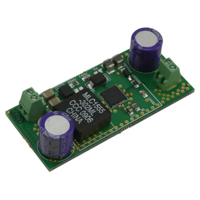
Figure 36. Schematic Diagram of NCP3101C Evaluation Board
120
C10
R1
732
33n
C9
11 12 13 14 15 16 17 18 19 20
COMP
220n
C7
10
9
8
PWRPHS
7
6
5
4
3
2
1
BG
2R2
47m
47m
OCPSET
RSN
40 39 38 37 36 35 34 33 32 31
R6
PWRVCC
IN
IN
C2
C1
D3
21
22
23
24
25
26
27
28
29
30
OR
R7
10R
L1
CSN
C8
3R3
2n2
220n
RBOOST
BAT54T1
CBOOST
D1
470
6.8 mH
PHASE
R3
510
1.6k
R2
1
3
2
22n
C13
R8
200
R8
20R
C4 +
C6
100m 100m 0.82m
C3
Q3
Q2
CLO3
RLO5
CLO2
RLO6
CLO1
RLO7
3
2
1
3
2
1
3
2
1
+
3
2
1
X1
OUT
OUT
RLO8
R5
270m
+ C5
D2
2xMBRS140T3
RLO4
RLO3
RLO2
RLO1
Q1
NCP3101C
�NCP3101C
ORDERING INFORMATION
Device
NCP3101CMNTXG
Temperature Grade
Package
Shipping†
For −40°C to +125°C
QFN40
(Pb−Free)
2500 / Tape & Reel
†For information on tape and reel specifications, including part orientation and tape sizes, please refer to our Tape and Reel Packaging
Specifications Brochure, BRD8011/D.
Microsoft Excel is a registered trademark of Microsoft Corporation.
http://onsemi.com
24
�MECHANICAL CASE OUTLINE
PACKAGE DIMENSIONS
QFN40 6x6, 0.5P
CASE 485AK−01
ISSUE A
DATE 26 OCT 2007
1 40
SCALE 2:1
A B
D
ÉÉÉ
ÉÉÉ
ÉÉÉ
PIN ONE
LOCATION
2X
NOTES:
1. DIMENSIONING AND TOLERANCING PER
ASME Y14.5M, 1994.
2. CONTROLLING DIMENSIONS: MILLIMETERS.
3. DIMENSION b APPLIES TO PLATED
TERMINAL AND IS MEASURED BETWEEN
0.15 AND 0.30mm FROM TERMINAL
4. COPLANARITY APPLIES TO THE EXPOSED
PAD AS WELL AS THE TERMINALS.
E
DIM
A
A1
A3
b
D
D2
D3
D4
D5
E
E2
E3
E4
e
G2
G3
K
L
0.15 C
2X
TOP VIEW
0.15 C
(A3)
0.10 C
A
SIDE VIEW A1
0.08 C
NOTE 4
C
D3
40X
SEATING
PLANE
G2
L
11
21
10
G3
D5
G2
E4
MILLIMETERS
MIN
MAX
0.80
1.00
−−−
0.05
0.20 REF
0.18
0.30
6.00 BSC
2.45
2.65
3.10
3.30
1.70
1.90
0.85
1.05
6.00 BSC
1.80
2.00
1.43
1.63
2.15
2.35
0.50 BSC
2.10
2.30
2.30
2.50
0.20
−−−
0.30
0.50
GENERIC
MARKING DIAGRAM*
1
11
XXXXXXXX
XXXXXXXX
AWLYYWWG
21
10
E2
1
E3
30
40
G3
31
e
40X
e/2
b
0.10 C A B
40
SOLDERING FOOTPRINT
6.30
0.72
1.86
0.72
2.62
0.92 1
0.72
1.58
1.96
6.30
2.31
0.92
31
K
NOTE 3
0.05 C
BOTTOM VIEW
30
1
G2
D2
AUXILIARY
BOTTOM VIEW
D4
G3
XXXXX
A
WL
YY
WW
G
= Specific Device Code
= Assembly Location
= Wafer Lot
= Year
= Work Week
= Pb−Free Package
*This information is generic. Please refer
to device data sheet for actual part
marking.
Pb−Free indicator, “G” or microdot “ G”,
may or may not be present.
0.50
PITCH
40X
0.30
40X
1.01
0.58
0.92
3.26
DIMENSIONS: MILLIMETERS
DOCUMENT NUMBER:
DESCRIPTION:
98AON24544D
QFN40 6x6, 0.5P
Electronic versions are uncontrolled except when accessed directly from the Document Repository.
Printed versions are uncontrolled except when stamped “CONTROLLED COPY” in red.
PAGE 1 OF 1
ON Semiconductor and
are trademarks of Semiconductor Components Industries, LLC dba ON Semiconductor or its subsidiaries in the United States and/or other countries.
ON Semiconductor reserves the right to make changes without further notice to any products herein. ON Semiconductor makes no warranty, representation or guarantee regarding
the suitability of its products for any particular purpose, nor does ON Semiconductor assume any liability arising out of the application or use of any product or circuit, and specifically
disclaims any and all liability, including without limitation special, consequential or incidental damages. ON Semiconductor does not convey any license under its patent rights nor the
rights of others.
© Semiconductor Components Industries, LLC, 2019
www.onsemi.com
�onsemi,
, and other names, marks, and brands are registered and/or common law trademarks of Semiconductor Components Industries, LLC dba “onsemi” or its affiliates
and/or subsidiaries in the United States and/or other countries. onsemi owns the rights to a number of patents, trademarks, copyrights, trade secrets, and other intellectual property.
A listing of onsemi’s product/patent coverage may be accessed at www.onsemi.com/site/pdf/Patent−Marking.pdf. onsemi reserves the right to make changes at any time to any
products or information herein, without notice. The information herein is provided “as−is” and onsemi makes no warranty, representation or guarantee regarding the accuracy of the
information, product features, availability, functionality, or suitability of its products for any particular purpose, nor does onsemi assume any liability arising out of the application or use
of any product or circuit, and specifically disclaims any and all liability, including without limitation special, consequential or incidental damages. Buyer is responsible for its products
and applications using onsemi products, including compliance with all laws, regulations and safety requirements or standards, regardless of any support or applications information
provided by onsemi. “Typical” parameters which may be provided in onsemi data sheets and/or specifications can and do vary in different applications and actual performance may
vary over time. All operating parameters, including “Typicals” must be validated for each customer application by customer’s technical experts. onsemi does not convey any license
under any of its intellectual property rights nor the rights of others. onsemi products are not designed, intended, or authorized for use as a critical component in life support systems
or any FDA Class 3 medical devices or medical devices with a same or similar classification in a foreign jurisdiction or any devices intended for implantation in the human body. Should
Buyer purchase or use onsemi products for any such unintended or unauthorized application, Buyer shall indemnify and hold onsemi and its officers, employees, subsidiaries, affiliates,
and distributors harmless against all claims, costs, damages, and expenses, and reasonable attorney fees arising out of, directly or indirectly, any claim of personal injury or death
associated with such unintended or unauthorized use, even if such claim alleges that onsemi was negligent regarding the design or manufacture of the part. onsemi is an Equal
Opportunity/Affirmative Action Employer. This literature is subject to all applicable copyright laws and is not for resale in any manner.
PUBLICATION ORDERING INFORMATION
LITERATURE FULFILLMENT:
Email Requests to: orderlit@onsemi.com
onsemi Website: www.onsemi.com
◊
TECHNICAL SUPPORT
North American Technical Support:
Voice Mail: 1 800−282−9855 Toll Free USA/Canada
Phone: 011 421 33 790 2910
Europe, Middle East and Africa Technical Support:
Phone: 00421 33 790 2910
For additional information, please contact your local Sales Representative
�


 工商网监
湘ICP备2023018690号
工商网监
湘ICP备2023018690号
