ON Semiconductor
Is Now
To learn more about onsemi™, please visit our website at
www.onsemi.com
onsemi and and other names, marks, and brands are registered and/or common law trademarks of Semiconductor Components Industries, LLC dba “onsemi” or its affiliates and/or
subsidiaries in the United States and/or other countries. onsemi owns the rights to a number of patents, trademarks, copyrights, trade secrets, and other intellectual property. A listing of onsemi
product/patent coverage may be accessed at www.onsemi.com/site/pdf/Patent-Marking.pdf. onsemi reserves the right to make changes at any time to any products or information herein, without
notice. The information herein is provided “as-is” and onsemi makes no warranty, representation or guarantee regarding the accuracy of the information, product features, availability, functionality,
or suitability of its products for any particular purpose, nor does onsemi assume any liability arising out of the application or use of any product or circuit, and specifically disclaims any and all
liability, including without limitation special, consequential or incidental damages. Buyer is responsible for its products and applications using onsemi products, including compliance with all laws,
regulations and safety requirements or standards, regardless of any support or applications information provided by onsemi. “Typical” parameters which may be provided in onsemi data sheets and/
or specifications can and do vary in different applications and actual performance may vary over time. All operating parameters, including “Typicals” must be validated for each customer application
by customer’s technical experts. onsemi does not convey any license under any of its intellectual property rights nor the rights of others. onsemi products are not designed, intended, or authorized
for use as a critical component in life support systems or any FDA Class 3 medical devices or medical devices with a same or similar classification in a foreign jurisdiction or any devices intended for
implantation in the human body. Should Buyer purchase or use onsemi products for any such unintended or unauthorized application, Buyer shall indemnify and hold onsemi and its officers, employees,
subsidiaries, affiliates, and distributors harmless against all claims, costs, damages, and expenses, and reasonable attorney fees arising out of, directly or indirectly, any claim of personal injury or death
associated with such unintended or unauthorized use, even if such claim alleges that onsemi was negligent regarding the design or manufacture of the part. onsemi is an Equal Opportunity/Affirmative
Action Employer. This literature is subject to all applicable copyright laws and is not for resale in any manner. Other names and brands may be claimed as the property of others.
�NCV7327
LIN Transceiver,
Stand-alone
Description
The NCV7327 is a fully featured local interconnect network (LIN)
transceiver designed to interface between a LIN protocol controller
and the physical bus.
The LIN bus is designed to communicate low rate data from control
devices such as door locks, mirrors, car seats, and sunroofs at the
lowest possible cost. The bus is designed to eliminate as much wiring
as possible and is implemented using a single wire in each node. Each
node has a slave MCU−state machine that recognizes and translates
the instructions specific to that function.
The main attraction of the LIN bus is that all the functions are not
time critical and usually relate to passenger comfort.
www.onsemi.com
MARKING
DIAGRAMS
8
SOIC−8
CASE 751AZ
8
1
1
Features
• LIN−Bus Transceiver
Compliant to ISO 17987−4 (Backwards Compatible to LIN
Specification rev. 2.x, 1.3) and SAE J2602
♦ Bus Voltage $42 V
♦ Transmission Rate up to 20 kbps (No low limit due to absence of
TxD Timeout function)
♦ Integrated Slope Control
Protection
♦ Thermal Shutdown
♦ Undervoltage Protection
♦ Bus Pins Protected Against Transients in an Automotive
Environment
Modes
♦ Normal Mode: LIN Transceiver Enabled, Communication via the
Bus is Possible
♦ Sleep Mode: LIN Transceiver Disabled, the Consumption from
VBB is Minimized
♦ Standby Mode: Transition Mode Reached after Wake−up Event on
the LIN Bus
Compatibility
♦ Pin−Compatible Subset with NCV7321
♦ K−line Compatible
♦ NCV7327 differs from NCV7329 only by absence of TxD
Timeout function
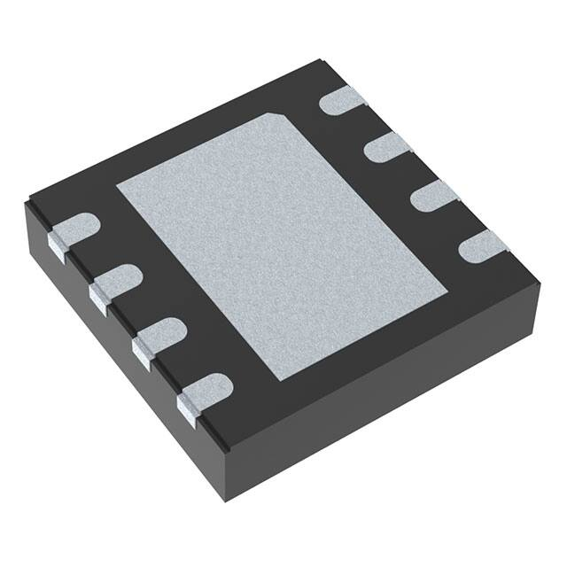
DFNW8
CASE 507AB
♦
•
•
•
• Wettable Flank Package for Enhanced Optical Inspection
• AEC−Q100 Qualified and PPAP Capable
• These Devices are Pb−Free, Halogen Free/BFR Free and are RoHS
Compliant
March, 2019 − Rev. 0
1
NV73
27−0
ALYWG
G
1
A
L
Y
W
G
= Assembly Location
= Wafer Lot
= Year
= Work Week
= Pb−Free Package
(Note: Microdot may be in either location)
PIN CONNECTIONS
RxD
EN
NC
TxD
1
8
2
7
3
6
4
5
NC
VBB
LIN
GND
SOIC−8 (Top View)
RxD 1
EN 2
NC 3
TxD 4
8 NC
EP
7 VBB
6 LIN
5 GND
DFNW8 (Top View)
Quality
© Semiconductor Components Industries, LLC, 2017
NV7327−0
ALYW
G
1
ORDERING INFORMATION
See detailed ordering and shipping information on page 10 of
this data sheet.
Publication Order Number:
NCV7327/D
�NCV7327
BLOCK DIAGRAM
VBB
POR
Isleep
EN
State
Thermal
shutdown
Control
DS
Osc
RSLAVE
+
RxD
COMP
−
TxD
Filter
LIN
Slope Control
NCV7327
GND
Figure 1. Block Diagram
TYPICAL APPLICATION
Slave Node
Master Node
2
5
GND
GND
TxD
EN
100 nF
10 μF
LIN
LIN
GND
GND
6
3
VCC
7
1
4
2
5
RxD
TxD
EN
GND
LB20140619.0
Microcontroller
3
4
8
220 pF
6
RxD
Microcontroller
1 nF
1
NCV7327
LIN
LIN
VBB
VCC
7
3.3/5V
NCV7327
10 μF
1 kΩ
VBB
8
10 kΩ
VBAT
3.3/5V
100 nF
VBAT
bat
10 kΩ
bat
GND
LB20140619.0
KL30
KL30
LIN−BUS
LIN−BUS
KL31
KL31
Figure 2. Typical Application Diagram for a Master Node
Table 1. PIN DESCRIPTION
Pin
Name
Description
1
RxD
Receive Data Output; Low in Dominant State; Open−Drain Output
2
EN
Enable Input, Transceiver in Normal Operation Mode when High, Pull−down Resistor to GND
3
NC
Not Connected
4
TxD
Transmit Data Input, Low for Dominant State, Pull−down to GND
5
GND
Ground
6
LIN
LIN Bus Output/Input
7
VBB
Battery Supply Input
8
NC
Not Connected
−
EP
Exposed Pad. Recommended to connect to GND or left floating in application (DFNW8 package only).
www.onsemi.com
2
�NCV7327
Table 2. ABSOLUTE MAXIMUM RATINGS
Symbol
Min
Max
Unit
VBB
Voltage on Pin VBB
−0.3
+42
V
VLIN
LIN Bus Voltage with respect to GND
−42
+42
V
LIN Bus Voltage with respect to VBB
−42
+42
V
DC Input Voltage on Pins (EN, RxD, TxD)
−0.3
+7
V
−8
+8
kV
V_Dig_IO
VESD
Parameter
Human Body Model (LIN Pin) (Note 1)
Human Body Model (All pins) (Note 1)
−4
+4
kV
Charged Device Model (All Pins) (Note 2)
−750
+750
V
Machine Model (All Pins) (Note 3)
−200
+200
V
Electrostatic Discharge Voltage (LIN Pin) System Human Body
Model (Note 4) Conform to IEC 61000−4−2
−8
+8
kV
TJ
Junction Temperature Range
−40
+150
°C
TSTG
Storage Temperature Range
−55
+150
°C
VESDIEC
MSLSOIC
Moisture sensitivity level for SOIC−8
2
−
MSLDFN
Moisture sensitivity level for DFNW8
1
−
260
°C
TSLD
Lead Temperature Soldering Reflow (SMD Styles Only),
Pb−Free Versions (Note 5)
Stresses exceeding those listed in the Maximum Ratings table may damage the device. If any of these limits are exceeded, device functionality
should not be assumed, damage may occur and reliability may be affected.
1. Standardized human body model electrostatic discharge (ESD) pulses in accordance to EIA−JESD22. Equivalent to discharging a 100 pF
capacitor through a 1.5 kW resistor.
2. Standardized charged device model ESD pulses when tested according to AEC−Q100−011.
3. In accordance to JEDEC JESD22−A115. Equivalent to discharging a 200 pF capacitor through a 10 W resistor and 0.75 mH coil.
4. Equivalent to discharging a 150 pF capacitor through a 330 W resistor. System HBM levels are verified by an external test−house.
5. For information, please refer to our Soldering and Mounting Techniques Reference Manual, SOLDERRM/D
Table 3. THERMAL CHARACTERISTICS
Parameter
Symbol
Value
Unit
Thermal characteristics, SOIC−8 (Note 6)
Thermal Resistance Junction−to−Air, Free air, 1S0P PCB (Note 7)
Thermal Resistance Junction−to−Air, Free air, 2S2P PCB (Note 8)
RqJA
RqJA
131
81
°C/W
°C/W
Thermal characteristics, DFNW8 (Note 6)
Thermal Resistance Junction−to−Air, Free air, 1S0P PCB (Note 7)
Thermal Resistance Junction−to−Air, Free air, 2S2P PCB (Note 8)
RqJA
RqJA
125
58
°C/W
°C/W
6. Refer to ELECTRICAL CHARACTERISTICS, RECOMMENDED OPERATING RANGES and/or APPLICATION INFORMATION for Safe
Operating parameters.
7. Values based on test board according to EIA/JEDEC Standard JESD51−3, signal layer with 10% trace coverage.
8. Values based on test board according to EIA/JEDEC Standard JESD51−7, signal layers with 10% trace coverage.
www.onsemi.com
3
�NCV7327
ELECTRICAL CHARACTERISTICS
Definitions
All voltages are referenced to GND (pin 5) unless otherwise specified. Positive currents flow into the IC. Sinking current means
the current is flowing into the pin; sourcing current means the current is flowing out of the pin.
Table 4. DC CHARACTERISTICS (VBB = 5 V to 18 V; TJ = −40°C to +150°C; Bus Load = 500 W (VBB to LIN); unless otherwise
specified. Typical values are given at VBB = 12 V and TJ = 25°C, unless otherwise specified.)
Parameter
Symbol
Conditions
Min
Typ
Max
Unit
5.0
−
18
V
SUPPY PIN (VBB)
VBB
Battery Supply Voltage
IBB
Battery Supply Current
Normal Mode; LIN Recessive
0.2
0.55
1.2
mA
IBB
Battery Supply Current
Normal Mode; LIN Dominant
2.0
3.9
6.5
mA
IBB
Battery Supply Current
Sleep and Standby Mode;
LIN Recessive; VLIN = VBB; TJ tENABLE
LIN rising edge after LIN = 0 for t > tLIN_WAKE
EN = Low for t > tDISABLE
Standby Mode
− LIN Transceiver: OFF
− LIN Term: 30 kW pull−up
− RxD: Low
EN = High for t > tENABLE
Normal Mode
− LIN Transceiver: ON
− LIN Term: 30 kW pull−up
− RxD Receives LIN Data
Figure 3. State Diagram
www.onsemi.com
8
�NCV7327
MEASUREMENT SETUPS AND DEFINITIONS
TxD
tBIT
tBIT
50%
t
tBUS_DOM(max)
LIN
tBUS_REC(min)
THREC(max)
THDOM(max)
Thresholds of
receiving node 1
THREC(min)
THDOM(min)
Thresholds of
receiving node 2
t
tBUS_DOM(min)
tBUS_REC(max)
Figure 4. LIN Transmitter Duty Cycle
LIN
VBB
60% VBB
40% VBB
t
RxD
tRX_PD
tRX_PD
50%
t
Figure 5. LIN Receiver Timing
LIN
Detection of Remote Wake−Up
VBB
LIN recessive level
tLIN_WAKE
60% VBB
tTO_STB
40% VBB
Sleep Mode
LIN dominant level
Standby Mode
Figure 6. Remote (LIN) Wake−up Detection
www.onsemi.com
9
t
�NCV7327
DEVICE ORDERING INFORMATION
Description
Temperature Range
Package
Shipping†
NCV7327D10R2G
LIN Transceiver, Stand−alone
−40°C to +150°C
SOIC−8
(Pb−Free)
3000 / Tape & Reel
NCV7327MW0R2G
LIN Transceiver, Stand−alone
−40°C to +150°C
DFNW8
(Pb−Free)
3000 / Tape & Reel
Part Number
†For information on tape and reel specifications, including part orientation and tape sizes, please refer to our Tape and Reel Packaging
Specifications Brochure, BRD8011/D.
www.onsemi.com
10
�NCV7327
PACKAGE DIMENSIONS
SOIC−8
CASE 751AZ
ISSUE B
NOTES 4&5
0.10 C D
45 5 CHAMFER
D
h
NOTE 6
D
A
8
H
2X
5
0.10 C D
E
E1
NOTES 4&5
L2
1
0.20 C D
4
8X
B
NOTE 6
TOP VIEW
b
0.25
M
L
C
DETAIL A
C A-B D
NOTES 3&7
DETAIL A
A2
NOTE 7
c
0.10 C
A
A1
NOTE 8
e
SIDE VIEW
SEATING
PLANE
C
END VIEW
SEATING
PLANE
RECOMMENDED
SOLDERING FOOTPRINT*
NOTES:
1. DIMENSIONING AND TOLERANCING PER ASME Y14.5M, 1994.
2. CONTROLLING DIMENSION: MILLIMETERS.
3. DIMENSION b DOES NOT INCLUDE DAMBAR PROTRUSION.
ALLOWABLE PROTRUSION SHALL BE 0.004 mm IN EXCESS OF
MAXIMUM MATERIAL CONDITION.
4. DIMENSION D DOES NOT INCLUDE MOLD FLASH, PROTRUSIONS
OR GATE BURRS. MOLD FLASH, PROTRUSIONS OR GATE BURRS
SHALL NOT EXCEED 0.006 mm PER SIDE. DIMENSION E1 DOES
NOT INCLUDE INTERLEAD FLASH OR PROTRUSION. INTERLEAD
FLASH OR PROTRUSION SHALL NOT EXCEED 0.010 mm PER SIDE.
5. THE PACKAGE TOP MAY BE SMALLER THAN THE PACKAGE BOT
TOM. DIMENSIONS D AND E1 ARE DETERMINED AT THE OUTER
MOST EXTREMES OF THE PLASTIC BODY AT DATUM H.
6. DIMENSIONS A AND B ARE TO BE DETERMINED AT DATUM H.
7. DIMENSIONS b AND c APPLY TO THE FLAT SECTION OF THE LEAD
BETWEEN 0.10 TO 0.25 FROM THE LEAD TIP.
8. A1 IS DEFINED AS THE VERTICAL DISTANCE FROM THE SEATING
PLANE TO THE LOWEST POINT ON THE PACKAGE BODY.
DIM
A
A1
A2
b
c
D
E
E1
e
h
L
L2
MILLIMETERS
MIN
MAX
--1.75
0.10
0.25
1.25
--0.31
0.51
0.10
0.25
4.90 BSC
6.00 BSC
3.90 BSC
1.27 BSC
0.25
0.41
0.40
1.27
0.25 BSC
8X
0.76
8X
1.52
7.00
1
1.27
PITCH
DIMENSIONS: MILLIMETERS
*For additional information on our Pb−Free strategy and soldering
details, please download the ON Semiconductor Soldering and
Mounting Techniques Reference Manual, SOLDERRM/D.
www.onsemi.com
11
�NCV7327
PACKAGE DIMENSIONS
DFNW8 3x3, 0.65P
CASE 507AB
ISSUE D
A
B
D
L3
L
ÉÉÉ
ÉÉÉ
ÉÉÉ
L
EXPOSED
COPPER
TOP VIEW
A1
A4
A
DETAIL B
0.05 C
PLATING
C
C
NOTE 4
A4
C
SIDE VIEW
SEATING
PLANE
D2
DETAIL A
1
DIM
A
A1
A3
A4
b
D
D2
E
E2
e
K
L
L3
DETAIL B
A3
0.05 C
8X
ALTERNATE
CONSTRUCTION
DETAIL A
E
PIN ONE
REFERENCE
NOTES:
1. DIMENSIONING AND TOLERANCING PER
ASME Y14.5M, 1994.
2. CONTROLLING DIMENSION: MILLIMETERS.
3. DIMENSION b APPLIES TO PLATED TERMINAL
AND IS MEASURED BETWEEN 0.10 AND
0.20mm FROM THE TERMINAL TIP.
4. COPLANARITY APPLIES TO THE EXPOSED
PAD AS WELL AS THE TERMINALS.
5. THIS DEVICE CONTAINS WETTABLE FLANK
DESIGN FEATURES TO AID IN FILLET FORMATION ON THE LEADS DURING MOUNTING.
L3
PLATED
SURFACES
L3
SECTION C−C
RECOMMENDED
SOLDERING FOOTPRINT*
4
2.55
2.28
L
E2
K
e/2
8
MILLIMETERS
MIN
NOM
MAX
0.80
0.85
0.90
−−−
−−−
0.05
0.20 REF
0.10
−−−
−−−
0.25
0.30
0.35
2.95
3.00
3.05
2.30
2.40
2.50
2.95
3.00
3.05
1.50
1.60
1.70
0.65 BSC
0.30 REF
0.35
0.40
0.45
0.00
0.05
0.10
5
e
BOTTOM VIEW
8X
b
8X
0.75
8
5
1
4
3.30 1.76
0.10 C A B
0.05 C
NOTE 3
0.65
PITCH
PACKAGE
OUTLINE
8X
0.33
DIMENSIONS: MILLIMETERS
*For additional information on our Pb−Free strategy and soldering
details, please download the ON Semiconductor Soldering and
Mounting Techniques Reference Manual, SOLDERRM/D.
ON Semiconductor and
are trademarks of Semiconductor Components Industries, LLC dba ON Semiconductor or its subsidiaries in the United States and/or other countries.
ON Semiconductor owns the rights to a number of patents, trademarks, copyrights, trade secrets, and other intellectual property. A listing of ON Semiconductor’s product/patent
coverage may be accessed at www.onsemi.com/site/pdf/Patent−Marking.pdf. ON Semiconductor reserves the right to make changes without further notice to any products herein.
ON Semiconductor makes no warranty, representation or guarantee regarding the suitability of its products for any particular purpose, nor does ON Semiconductor assume any liability
arising out of the application or use of any product or circuit, and specifically disclaims any and all liability, including without limitation special, consequential or incidental damages.
Buyer is responsible for its products and applications using ON Semiconductor products, including compliance with all laws, regulations and safety requirements or standards,
regardless of any support or applications information provided by ON Semiconductor. “Typical” parameters which may be provided in ON Semiconductor data sheets and/or
specifications can and do vary in different applications and actual performance may vary over time. All operating parameters, including “Typicals” must be validated for each customer
application by customer’s technical experts. ON Semiconductor does not convey any license under its patent rights nor the rights of others. ON Semiconductor products are not
designed, intended, or authorized for use as a critical component in life support systems or any FDA Class 3 medical devices or medical devices with a same or similar classification
in a foreign jurisdiction or any devices intended for implantation in the human body. Should Buyer purchase or use ON Semiconductor products for any such unintended or unauthorized
application, Buyer shall indemnify and hold ON Semiconductor and its officers, employees, subsidiaries, affiliates, and distributors harmless against all claims, costs, damages, and
expenses, and reasonable attorney fees arising out of, directly or indirectly, any claim of personal injury or death associated with such unintended or unauthorized use, even if such
claim alleges that ON Semiconductor was negligent regarding the design or manufacture of the part. ON Semiconductor is an Equal Opportunity/Affirmative Action Employer. This
literature is subject to all applicable copyright laws and is not for resale in any manner.
PUBLICATION ORDERING INFORMATION
LITERATURE FULFILLMENT:
Literature Distribution Center for ON Semiconductor
19521 E. 32nd Pkwy, Aurora, Colorado 80011 USA
Phone: 303−675−2175 or 800−344−3860 Toll Free USA/Canada
Fax: 303−675−2176 or 800−344−3867 Toll Free USA/Canada
Email: orderlit@onsemi.com
◊
N. American Technical Support: 800−282−9855 Toll Free
USA/Canada
Europe, Middle East and Africa Technical Support:
Phone: 421 33 790 2910
www.onsemi.com
12
ON Semiconductor Website: www.onsemi.com
Order Literature: http://www.onsemi.com/orderlit
For additional information, please contact your local
Sales Representative
NCV7327/D
�


 工商网监
湘ICP备2023018690号
工商网监
湘ICP备2023018690号
