Infrared Light Emitting Diode in SMD Plastic Package
OP270 Series
• • • • •
890nm Wavelength Narrow Beam Angle High Power 1.9mm Water Clear Plastic Package Four Lead Configurations
Description:
The OP270 series are GaAlAs infrared LEDs mounted in a clear plastic SMT packages. The devices incorporate an integral molded lens which enables a narrow beam angle and provides an even emission pattern. This series is available with four lead configurations and is compatible with most automated mounting equipment. The OP270 Series LEDs are mechanically and spectrally matched to the OP570 series phototransistors.
Applications
• • • Non-Contact Position Sensing Datum detection Machine automation • • • Optical encoders IrDA Reflective and Transmissive Sensors
Relative Radiant Intensity vs. Angular Displacement
100%
OP272 OP271 OP273
Relative Radiant Intensity
80%
60%
40%
OP270
20% 0% -90 -60 -30 0 30 60 90 Angular Displacement (Degrees)
Pb
RoHS
A subsidiary of TT electronics plc
Optek reserves the right to make changes at any time in order to improve design and to supply the best product possible. OPTEK Technology Inc.— 1645 Wallace Drive, Carrollton, Texas 75006 Phone: (800) 341-4747 FAX: (972) 323– 2396 sensors@optekinc.com www.optekinc.com
�SMD Infrared LED
OP270 Series
Absolute Maximum Ratings (TA = 25o C unless otherwise noted)
PARAMETER
Continuous Forward Current Power Dissipation Reverse Voltage Peak Forward Current (1μs pulse width, 300 pps) Lead Soldering Temperature (1.6mm to epoxy for 5 sec.) Operating Temperature Range Storage Temperature Range Notes: 1. Solder time less than 5 seconds at temperature extreme. 2. De-rate linearly at 2.17 mW/° C above 25° C. TSOL TOPR TSTG 260º -40ºC to +85ºC -40ºC to +100ºC C
SYMBOL
IF Pd IR IFP
MAXIMUM
50 130 2 1
UNITS
mA mW V A
Electrical Characteristics (TA = 25°C unless otherwise noted)
SYMBOL
Ee(APT) VF IR λP ΘHP tr, tf 3.
PARAMETER
Apertured Radiant Incidence Forward Voltage Reverse Current Peak Emission Wavelength Emission Angle at Half Power Points Rise and Fall Time
MIN
1.5
TYP
MAX
UNITS
mW/cm
2
CONDITIONS
IF = 20mA IF = 20mA VR = 2.0V IF = 10mA IF = 20mA IF(PEAK) = 100mA, PW = 10µs, 10% D.C.
(3)
1.5 100 890 25 500
V µA nm Deg. ns
Ee(APT) is a measurement of the apertured radiant incidence upon a sensing area 0.081” (2.06mm) in diameter, perpendicular to and centered on the mechanical axis of the lens, and 0.590” (14.99mm) from the measurement surface. Ee(APT) is not necessarily uniform within the measured area.
350% 300%
Relative Radiant Intensity vs. Forward Current vs. Temperature
Normalized at IF = 20mA, TA = 20°C. Temperatures stepped in 20°C Increments
Forward Voltage vs. Forward Current vs. Temperature
1.5
Temperatures stepped in 20 °C Increments -40°C
-40°C
Relative Radiant Intensity
1.4
Forward Voltage (V)
250% 200% 150% 100% 50%
100°C
1.3
100°C
1.2
1.1
0
10
20
30
40
50
1.0
0
10
20
30
40
50
Forward Current (mA)
OPTEK Technology Inc.— 1645 Wallace Drive, Carrollton, Texas 75006 Phone: (800) 341-4747 FAX: (972) 323– 2396 sensors@optekinc.com www.optekinc.com
Forward Current (mA)
Issue A.3 07/08 Page 2 of 3
�SMD Infrared LED
OP270 Series
OP270
OP271
1
2
PIN 1 2
LED A K
PIN 1 2
LED A K
OP272
OP273
1
2
PIN 1 2
LED A K
PIN 1 2
LED A K
OPTEK Technology Inc.— 1645 Wallace Drive, Carrollton, Texas 75006 Phone: (800) 341-4747 FAX: (972) 323– 2396 sensors@optekinc.com www.optekinc.com
Issue A.3 07/08 Page 3 of 3
�
很抱歉,暂时无法提供与“OP270”相匹配的价格&库存,您可以联系我们找货
免费人工找货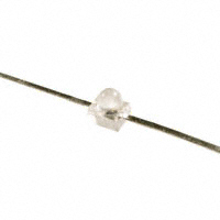


 工商网监
湘ICP备2023018690号
工商网监
湘ICP备2023018690号
