Ultraviolet (UV) Metal Can LED OUE8A Series
Features:
• • • • • •
Peak Wavelengths from 380 nm to 425 nm Uniform Optical Light Pattern High Pulse Current Hermetic TO-46 Metal Can Package RoHs Compliant—No Mercury ESD Protected
The OUE8A Series offers an energy-efficient hermetic TO-46 metal can packaged UV LED source providing a uniform optical light pattern, high current pulse capability, ESD protection and a long operating lifespan. Devices have a 18o typical emission angle with peak wavelengths from 375 nm to 425 nm. In order to meet critical wavelength requirements of the industry, the OUE8A Series is divided into groups each with a total wavelength range of only 5 nm. Each wavelength range is subdivided into optical power output ranges from a minimum of 1.8 mW to over 17.0 mW based on power out specifications listed below.
Applications:
• • • • •
Adhesive-Ink Photo Catalyst Curing Currency / Passport Validation Spectroscopy Forensic Medical
Part Number
Emission Angle
Peak Wavelength (nm) IF = 100 mA
Range 375 to 380 380 to 385 385 to 390 390 to 395
Optical Power Output (mW) IF = 100 mA
Minimum 1.8 1.8 1.8 3.1 5.8 5.8 5.8 7.3 7.3 7.3 Maximum 8.1 8.1 8.1 9.8 13.4 13.4 13.4 15.4 15.4 15.4
OUE8A380Y1 OUE8A385Y1 OUE8A390Y1 OUE8A395Y1 OUE8A400Y1 OUE8A405Y1 OUE8A410Y1 OUE8A415Y1 OUE8A420Y1 OUE8A425Y1 18
395 to 400 400 to 405 405 to 410 410 to 415 415 to 420 420 to 425
Part Number Guide
OUE8 A XXX Y 1
Optek UV TO-46 LED Series Sequence Numbers (A→Z) Packaging 1 – Tray Pack Power Output (mW) - A through J Wavelength (nm) Identifier
ESD Level ≥ 8,000 V
Warnings and Handling Instructions
UV-LEDs emit invisible ultraviolet radiation when in operation, which may be harmful to eyes or skin, even for brief periods. Do NOT look directly into the UV-LED during operation. Be sure that you and all persons in the vicinity wear adequate “UV” Safety protection for eyes and skin. If you incorporate a UV-LED into a product, be sure to provide appropriate WARNING labels.
RoHs
OPTEK reserves the right to make changes at any time in order to improve design and to supply the best product possible. Issue A.2 07/09 Page 1 of 8
OPTEK Technology Inc. — 1645 Wallace Drive, Carrollton, Texas 75006 Phone: (972) 323-2200 or (800) 341-4747 FAX: (972) 323-2396 sensors@optekinc.com www.optekinc.com
�Ultraviolet (UV) Metal Can LED OUE8A Series
Absolute Maximum Ratings (TA=25°C unless otherwise noted)
Storage Temperature Range Operating Temperature Range Allowable Reverse Current (IR) Continuous Forward Current Peak Pulsed Forward Current (Pulse Width 100 usec @ 10% duty cycle) Lead Soldering Temperature [1/16 inch (1.6 mm) from case for 5 seconds with soldering iron] Power Dissipation
Notes: 1. RMA flux is recommended. Duration can be extended to 10 seconds maximum when wave soldering.
-40o C to +125o C -40o C to +85o C 85 mA 100 mA 1.6 A 260° C(1) 370 mW
Electrical & Optical Characteristics (TA = 25°C unless otherwise noted)
SYMBO L VF ΔVF/ΔT ∆λP ∆λP /∆T ΔPo/ΔT θHP Forward Voltage VF Temperature Co-efficient Spectral Half Width Peak Spectral Shift with Temperature Power Output Drop Temperature Co-efficient Emission Angle at Half Power Points PARAMETER MIN 3.0 TYP 3.3 -4.8 12 0.035 -0.2 18 MAX 3.7 UNITS V mV/oC nm nm/°C %/oC Degree IF = 20 mA IF = 100 mA TEST CONDITIONS
Pin 2 Pin 1 Pin 2
Pin 1 Cathode Anode
[13.20] 0.520
Part Number Date Code
Dimensions are in inches [ mm]
OPTEK reserves the right to make changes at any time in order to improve design and to supply the best product possible. Issue A.2 Page 2 of 8 07/09 OPTEK Technology Inc. — 1645 Wallace Drive, Carrollton, Texas 75006 Phone: (972) 323-2200 or (800) 341-4747 FAX: (972) 323-2396 sensors@optekinc.com www.optekinc.com
�Ultraviolet (UV) Metal Can LED OUE8A Series
Standard Optical Power Bins • Devices are sorted to Optical Power Out (mW) as shown below. • Unless designated, orders may be filled with any or all bins contained.
Power Bin Identification
OUE8AxxxA OUE8AxxxB OUE8AxxxC OUE8AxxxD OUE8AxxxE OUE8AxxxF OUE8AxxxG OUE8AxxxH OUE8AxxxI OUE8AxxxJ • •
Optical Power Out (mW) IF = 100 mA @ 25oC
Bin Minimum 0.5 1.8 3.1 4.5 5.8 7.3 8.8 10.4 12.1 13.9 Bin Maximum 2.0 3.5 4.9 6.5 8.1 9.8 11.5 13.4 15.4 17.6
Where xxx = Part Number Wavelength (nm) on page 1 Parts for a specific Power Bin are subject to availability.
Spatial Intensity Distribution
TA = 25°C IF = 20 mA
18 degrees Typical Normalized Spectral Intensity vs. Angular Displacement
OPTEK reserves the right to make changes at any time in order to improve design and to supply the best product possible. OPTEK Technology Inc. — 1645 Wallace Drive, Carrollton, Texas 75006 Phone: (972) 323-2200 or (800) 341-4747 FAX: (972) 323-2396 sensors@optekinc.com www.optekinc.com Issue A.2 07/09 Page 3 of 8
�Ultraviolet (UV) Metal Can LED OUE8A Series
Relative Power Output vs Junction Temperature
1.2
120
Junction Temperature vs. Maximum Allowable Forward Current
1.0
Maximum Allowable Forward Current IF [mA]
100
Relative Power Output (mW)
0.8
80
0.6
60
0.4
40
0.2
20
0.0 0 20 40 60
o
0
80
100
0
20
40
60
80
100
Junction Temperature ( C)
Junction Temperature, TJ [°C]
Normalized Peak Spectral Responses
1.2 380nm 383nm 1
Duty Ratio vs. Allowable Forward Current T = 1 ms & variable PW
6,000 TA = 25°C
Allowable Pulsed Forward Current [mA]
386nm 391nm 399nm
5,000
Peak Response (W/nm)
0.8
407nm 409nm
4,000
0.6
3,000
0.4
2,000
0.2
1,000
0 350
-
400
450
1
10
100
Wavelength (nm)
Duty Ratio (%)
OPTEK reserves the right to make changes at any time in order to improve design and to supply the best product possible. Issue A.2 Page 4 of 8 07/09 OPTEK Technology Inc. — 1645 Wallace Drive, Carrollton, Texas 75006 Phone: (972) 323-2200 or (800) 341-4747 FAX: (972) 323-2396 sensors@optekinc.com www.optekinc.com
�Ultraviolet (UV) Metal Can LED OUE8A Series
Peak Wavelength vs Junction Temperature
1.010
* no rmalized to 25°C ** peak wavelength = wavelength o f part multiplied by y-axis scale
Forward Volta ge vs. Forward Current
400 TA = 25°C 350 300 [ mA] Forward Current I
FP
1.008
Peak Wavelength λ [nm] **
1.006
250 200 150 100 50 0
1.004
1.002
Linear (390 nm) Linear (41 nm) 0
1.000
0.998
0.996 0 20 40 60 80 100 120
2.5
2.7
2.9
3.1
3.3
3.5
3.7
Junction Temperature TA [°C]
Forw ard Voltage V F [ V]
Typical Power Out vs. Forward Current
2.0 TA = 25°C 1.8
Typical Peak Wavelength vs. Forward Current
1.0020 1.0015
* no rmalized to 1 mA 00 ** peak wavelength = wavelength o f part multiplied by y-axis scale
Normalized Power Out [W]
1.6
Typ. Peak Wavelength [nm] **
1.4 1.2 1.0 0.8 0.6 0.4 0.2 0.0 0 50 100 150 200
1.0010 1.0005 1.0000 0.9995 0.9990 0.9985 0.9980 0 50 100
Linear (41 nm) 0 Linear (390 nm)
150
200
Forward Current [mA]
Forw ard Current [m A]
OPTEK reserves the right to make changes at any time in order to improve design and to supply the best product possible. OPTEK Technology Inc. — 1645 Wallace Drive, Carrollton, Texas 75006 Phone: (972) 323-2200 or (800) 341-4747 FAX: (972) 323-2396 sensors@optekinc.com www.optekinc.com Issue A.2 07/09 Page 5 of 8
�Ultraviolet (UV) Metal Can LED OUE8A Series
Reliability Test
ITEM Life Test Temperature Humidity Operating High Temperature Operating Low Temperature Operating Thermal Shock Resistance to Soldering Heat High Temperature Storage Low Temperature Storage CONDITION TA = RT, IF = 20 mA NOTE 1000 hrs FAILURES 0/22
TA = RT, IF = 20 mA, RH = 90% TA = 80ºC, IF = 5 mA TA = -40ºC, IF =20 mA TA = -40ºC (30 min) to +85ºC (30 min) [Transfer Time: 5 sec, 1 cycle = 1hr] Ts = 260 ± 5ºC, Time = 5 ± 1 sec TA = +100ºC TA = -40ºC
1000 hrs 1000 hrs 1000 hrs 100 cycles 1 time 1000 hrs 1000 hrs
0/22 0/22 0/22 0/22 0/11 0/22 0/22
Criteria for judging damage
CRITERIA FOR JUDGEMENT ITEM SYMBOL MEASURING CONDITION Minimum Forward Voltage Optical Power Output
Notes: 1. 2. 3. 4. 5. 6. 7.
Maximum USL X 1.1 -
VF PO
IF = 20 mA IF = 20 mA
LSL X 0.5
IF = Forward Current LSL = Lower Specification Limit RH = Relative humidity RT = Room Temperature ~ 25°C TA = Ambient Temperature TS = Solder Temperature USL = Upper Specification Limit
OPTEK reserves the right to make changes at any time in order to improve design and to supply the best product possible. Issue A.2 Page 6 of 8 07/09 OPTEK Technology Inc. — 1645 Wallace Drive, Carrollton, Texas 75006 Phone: (972) 323-2200 or (800) 341-4747 FAX: (972) 323-2396 sensors@optekinc.com www.optekinc.com
�Ultraviolet (UV) Metal Can LED OUE8A Series
Stress results
Test Operating Life Samples 22 Test conditions 1008 hours, TA @ 25ºC, 100mW operation, IF = 27.7mA Total assembly hours 22,176 Failures 0/22
D&O 380nm UVLED Build 1 - 100mW burn-in Group H Tested at IF = 350 mA, T A = 25°C
25.00
20.00
Pt/mW
15.00
average min max +3σ -3σ
10.00
5.00
0.00 0 200 400 600 800 1000 1200
hours
OPTEK reserves the right to make changes at any time in order to improve design and to supply the best product possible. OPTEK Technology Inc. — 1645 Wallace Drive, Carrollton, Texas 75006 Phone: (972) 323-2200 or (800) 341-4747 FAX: (972) 323-2396 sensors@optekinc.com www.optekinc.com Issue A.2 07/09 Page 7 of 8
�Ultraviolet (UV) Metal Can LED OUE8A Series
Shipping Information: Optek UV LEDs are shipped in either of the below noted conductive trays made for ESD sensitive devices. Each tray contains up to 100 pieces and is then sealed in a plastic ESD bag. Tray dimensions are in inches (mm).
14.76 4X 0.500 [12.70] 100X 0.250 100X 0.190
13.0
100X 0.250 100X 1.320
POCKET DETAIL
OPTEK reserves the right to make changes at any time in order to improve design and to supply the best product possible. Issue A.2 Page 8 of 8 07/09 OPTEK Technology Inc. — 1645 Wallace Drive, Carrollton, Texas 75006 Phone: (972) 323-2200 or (800) 341-4747 FAX: (972) 323-2396 sensors@optekinc.com www.optekinc.com
�
很抱歉,暂时无法提供与“OUE8A425Y1”相匹配的价格&库存,您可以联系我们找货
免费人工找货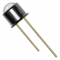


 工商网监
湘ICP备2023018690号
工商网监
湘ICP备2023018690号
