Full Color PLCC4 LED
OVSARGB3R8
Surface mount device packaged in 8mm tape on 7” diameter reel Compatible with automatic placement equipment Compatible with infrared and vapor phase reflow solder Pb-free, RoHS-compliant Dimensions: 3.5x2.8x1.9mm 120° viewing angle
x x x x x x
Product Photo Here
The OVSARGB3R8 provides full color light output from a single package, 3-die design. This surface mount package is an efficient solution in modular applications that require uniform brightness and color-on-demand. Light output is optimized by an interior reflector and the wide viewing angle adds flexibility for applications ranging from hand-held appliances to automotive interiors. Applications x RGB+White Full-color Indoor and Outdoor Displays x Backlighting x Coupling into Lightguides x Automotive Interiors x Entertainment Equipment
Part Number Chip Emitted Color Red Green Blue Lens Color Water Clear
OVSARGB3R8
Type R G B
Material AlInGaP InGaN InGaN
Intensity Typ. mcd 300 450 110
RoHS
1,3,4 CATHODE
2 ANODE
DIMENSIONS ARE IN INCHES AND [MILLIMETERS].
Data is subject to change without prior notice. OPTEK Technology Inc. — 1645 Wallace Drive, Carrollton, Texas 75006 Phone: (800) 341-4747 FAX: (972) 323-2396 sensors@optekinc.com www.optekinc.com Issue 1.0 0605 Page 1
�Full-Color PLCC4 LED
OVSARGB3R8
Absolute Maximum Ratings
TA = 25o C unless otherwise noted
PARAMETER Storage Temperature Operating Temperature Reverse Voltage Continuous Forward Current
1
RATING R G -40 ~ +100 -40 ~ +100 5 50 200 130 110 25 100 105 110 400 580 280 430 25 100 105 110 450 680 300 480 B
UNIT ° C ° C V mA mA mW ° C ° C/W ° C/W ° C/W ° C/W
Peak Forward Current (10% Duty Cycle, PW ��� sec) Power Dissipation Junction Temperature Junction/ambient (1 chip on ) Junction/ambient (3 chips on2) Junction/solder point (1 chip on) Junction/solder point (3 chips on)
2
450 650 300 450
Electrical Characteristics
TA = 25o C unless otherwise noted
SYMBOL PARAMETER Min Typ Typ Max VALUES R 180 300 2.3 2.6 10 612–625 620 120 24 G 280 450 3.6 4.2 10 520–540 520 120 38 B 71 110 3.6 4.2 10 460–480 465 120 28 UNIT CONDITIONS
IV
Luminous Intensity
VF IR
D P
Forward Voltage Reverse Current (max) Dominant Wavelength Wavelength at Peak Emission 50% Power Angle Spectrum Radiation Bandwidth
2
½
Issue 1.0 Page 2
0605
¥§¦¤¢ ¥£¡
Notes: 1. Single color light 2. Rth test condition: Mounted on PC Board FR 4 (pad size
2
)
mcd
IF = 20mA
V µA nm nm deg nm
IF = 20mA VR = 5V IF = 20mA IF = 20mA IF = 20mA IF = 20mA
OPTEK Technology Inc. — 1645 Wallace Drive, Carrollton, Texas 75006 Phone: (800) 341-4747 FAX: (972) 323-2396 sensors@optekinc.com www.optekinc.com
�Full-Color PLCC4 LED
OVSARGB3R8 Standard Bins (IF=20mA)
Lamps are sorted to luminous intensity (IV) and dominant wavelength ( D) bins shown. Orders for OVSARGB3R8 may be filled with any or all bins contained as below.
RED
Luminous Intensity (mcd)
450 280 180 612 T S Luminous intensity is at S bin or above.
Dominant Wavelength (nm)
625
GREEN
Luminous Intensity (mcd)
710 450 280 520 U T Luminous intensity is at T bin or above.
Dominant Wavelength (nm)
540
BLUE
Luminous Intensity (mcd)
180 112 71 460 R Q Luminous intensity is at Q bin or above.
Dominant Wavelength (nm)
480
Important Notes: 1. All ranks will be included per delivery, rank ratio will be based on the chip distribution. 2. Tolerance of measurement of luminous intensity is ±10%. 3. Tolerance of measurement of dominant wavelength is ±1nm. 4. Tolerance of measurement of VF is ±0.05V.
OPTEK Technology Inc. — 1645 Wallace Drive, Carrollton, Texas 75006 Phone: (800) 341-4747 FAX: (972) 323-2396 sensors@optekinc.com www.optekinc.com
Issue 1.0
0605 Page 3
�Full-Color PLCC4 LED
OVSARGB3R8 Typical Electro-Optical Characteristics Curves
Relative Intensity vs. Dominant Wave Length
IF(mA)
IF(mA)
VF(V)
Forward Current vs. Forward Voltage
VF(V)
Percent (%)
Percent (%)
IF(mA)
IF(mA)
Relative Luminous Intensity vs. Forward Current
Issue 1.0 Page 4
0605
OPTEK Technology Inc. — 1645 Wallace Drive, Carrollton, Texas 75006 Phone: (800) 341-4747 FAX: (972) 323-2396 sensors@optekinc.com www.optekinc.com
�Full-Color PLCC4 LED
OVSARGB3R8 Typical Electro-Optical Characteristics Curves
1 Chip On 3 Chips On
IF(mA)
IF(mA)
TA(° C)
TA(° C)
Maximum Forward DC Current vs. Solder Point Temperature
1 Chip On
3 Chips On
IF(mA)
IF(mA)
TA(° C)
TA(° C)
Maximum Forward DC Current vs. Ambient Temperature
50% Power Angle: 120°
Far Field Pattern
OPTEK Technology Inc. — 1645 Wallace Drive, Carrollton, Texas 75006 Phone: (800) 341-4747 FAX: (972) 323-2396 sensors@optekinc.com www.optekinc.com Issue 1.0 0605 Page 5
�Full-Color PLCC4 LED
OVSARGB3R8 CIE Graph
The color coordinates of the mixed light can be expected within the area of the color triangle marked a). The achromatic point (x =0.33, y=0.33) is marked “+”.
Issue 1.0 Page 6
0605
OPTEK Technology Inc. — 1645 Wallace Drive, Carrollton, Texas 75006 Phone: (800) 341-4747 FAX: (972) 323-2396 sensors@optekinc.com www.optekinc.com
�Full-Color PLCC4 LED
OVSARGB3R8 Reel Dimensions (7 Inch)
Carrier Tape Dimensions: Loaded Quantity 2000 PCS per Reel
Moisture Resistant Packaging
Label
Aluminum Moisture-proof Bag
Desiccant
Bar Code Label
OPTEK Technology Inc. — 1645 Wallace Drive, Carrollton, Texas 75006 Phone: (800) 341-4747 FAX: (972) 323-2396 sensors@optekinc.com www.optekinc.com
Issue 1.0
0605 Page 7
�Full-Color PLCC4 LED
OVSARGB3R8
Issue
Change Description
Approval
Date
1.0
Initial Release
J. Haynie
6/30/05
Issue 1.0 Page 8
0605
OPTEK Technology Inc. — 1645 Wallace Drive, Carrollton, Texas 75006 Phone: (800) 341-4747 FAX: (972) 323-2396 sensors@optekinc.com www.optekinc.com
�
很抱歉,暂时无法提供与“OVSARGB3R8”相匹配的价格&库存,您可以联系我们找货
免费人工找货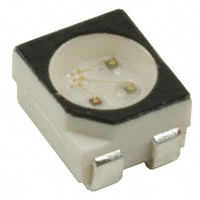


 工商网监
湘ICP备2023018690号
工商网监
湘ICP备2023018690号
