AXE5, 6
Narrow-pitch connectors
The 2.5 mm wide ultra-slim body contributes to further miniaturization and functionality enhancement of target equipment.
NARROW PITCH (0.4 mm) CONNECTORS For Board-to-FPC ADVANCED SERIES A4S
4. Mated heights of 0.8 and 1.0 mm are available for the same foot pattern. 5. Connectors for inspection available (See page 31 for details of the structure)
FEATURES
1. 2.5 mm wide ultra-slim two-piece connectors The ultra-compact and slim body contributes to further miniaturization and functionality enhancement of target equipment. • Width: 30% down • Footprint: 30% down
F4S
APPLICATIONS
Recommended for board-to-FPC connections of mobile equipment, such as cellular phones, smart phones, notebook PCs, and portable music players
Socket
Header
Compliance with RoHS Directive
1.0 0.8
A4S
2.5 3.6
2. “ ” structure adopted to ensure high resistance to various environments in spite of the ultra-slim and low profile body 3. The simple lock structure for good mating/unmating operation feel.
Simple lock structure
Double contact Simple lock
V-notch
The connector gives the tactile feedback when inserted, allowing reliable mating.
ORDERING INFORMATION
AXE
5: Narrow Pitch Connector A4S (0.4 mm pitch) Socket 6: Narrow Pitch Connector A4S (0.4 mm pitch) Header Number of contacts (2 digits) Mated height 1: For mated height 0.8/1.0 mm 1: For mated height 0.8 mm 2: For mated height 1.0 mm Functions 2: Without positioning bosses Surface treatment (Contact portion / Terminal portion) 4: Ni plating on base, Au plating on surface (for Ni barrier available) 4: Ni plating on base, Au plating on surface
1
2
4
panasonic-electric-works.net/ac
�AXE5, 6
Mated height Number of contacts 10 12 14 16 18 20 22 24 26 28 30 32 34 36 38 40 44 50 54 60 64 70 80 10 14 20 24 30 40 50 54 60 70 80 Part number Socket AXE510124 AXE512124 AXE514124 AXE516124 AXE518124 AXE520124 AXE522124 AXE524124 AXE526124 AXE528124 AXE530124 AXE532124 AXE534124 AXE536124 AXE538124 AXE540124 AXE544124 AXE550124 AXE554124 AXE560124 AXE564124 AXE570124 AXE580124 AXE510124 AXE514124 AXE520124 AXE524124 AXE530124 AXE540124 AXE550124 AXE554124 AXE560124 AXE570124 AXE580124 Header AXE610124 AXE612124 AXE614124 AXE616124 AXE618124 AXE620124 AXE622124 AXE624124 AXE626124 AXE628124 AXE630124 AXE632124 AXE634124 AXE636124 AXE638124 AXE640124 AXE644124 AXE650124 AXE654124 AXE660124 AXE664124 AXE670124 AXE680124 AXE610224 AXE614224 AXE620224 AXE624224 AXE630224 AXE640224 AXE650224 AXE654224 AXE660224 AXE670224 AXE680224 Inner carton (1-reel) Packing Outer carton
0.8mm
5,000 pieces
10,000 pieces
1.0mm
Notes: 1. Order unit: For mass production: in 1-inner carton (1-reel) units Samples for mounting check: in 50-connector units. Please contact our sales office. Samples: Small lot orders are possible. Please contact our sales office. 2. The above part numbers are for connectors without positioning bosses, which are standard. When ordering connectors with positioning bosses, please contact our sales office. 3. Please contact us for connectors having a number of contacts other than those listed above.
panasonic-electric-works.net/ac
Narrow-pitch connectors
PRODUCT TYPES
�AXE5, 6
Narrow-pitch connectors
SPECIFICATIONS
Characteristics
Item Rated current Rated voltage Electrical characteristics Breakdown voltage Insulation resistance Contact resistance Composite insertion force Composite removal force Contact holding force (Socket contact) Ambient temperature Soldering heat resistance Storage temperature Specifications 0.3A/contact (Max. 5 A at total contacts) 60V AC/DC 150V AC for 1 min. Min. 1,000MΩ (initial) Max. 90mΩ Max. 1.200N/contacts × contacts (initial) Min. 0.165N/contacts × contacts Min. 0.20N/contacts –55°C to +85°C Peak temperature: 260°C or less (on the surface of the PC board around the connector terminals) 300°C within 5 sec. 350°C within 3 sec. –55°C to +85°C (product only) –40°C to +50°C (emboss packing) 5 cycles, insulation resistance min. 100MΩ, contact resistance max. 90mΩ 120 hours, insulation resistance min. 100MΩ, contact resistance max. 90mΩ 24 hours, insulation resistance min. 100MΩ, contact resistance max. 90mΩ 48 hours, contact resistance max. 90mΩ 30 times 20-contact type: Socket: 0.02 g Header: 0.01 g Measuring the maximum force. As the contact is axially pull out. No freezing at low temperatures. No dew condensation. Infrared reflow soldering Soldering iron No freezing at low temperatures. No dew condensation. Sequence 1. –55 −0 °C, 30 minutes 3 2. ~ , Max. 5 minutes +3 3. 85 0 °C, 30 minutes 4. ~ , Max. 5 minutes Bath temperature 40±2°C, humidity 90 to 95% R.H. Bath temperature 35±2°C, saltwater concentration 5±1% Bath temperature 40±2°C, gas concentration 3±1 ppm, humidity 75 to 80% R.H. Repeated insertion and removal speed of max. 200 times/ hours Conditions
No short-circuiting or damage at a detection current of 1 mA when the specified voltage is applied for one minute. Using 250V DC megger (applied for 1 min.) Based on the contact resistance measurement method specified by JIS C 5402.
Mechanical characteristics
Environmental characteristics
Thermal shock resistance (header and socket mated)
Humidity resistance (header and socket mated) Saltwater spray resistance (header and socket mated) H2S resistance (header and socket mated) Lifetime characteristics Unit weight Insertion and removal life
Material and surface treatment
Part name Molded portion Contact and Post Material LCP resin (UL94V-0) Surface treatment — Contact portion: Base: Ni plating Surface: Au plating Terminal portion: Base: Ni plating Surface: Au plating (except the terminal tips) The socket terminals close to the portion to be soldered have nickel barriers (exposed nickel portions). Metal clips: Sockets: Base: Ni plating Surface: Pd+Au flash plating (except the terminal tips) Headers: Base: Ni plating Surface: Au plating (except the terminal tips)
Copper alloy
panasonic-electric-works.net/ac
�AXE5, 6
The CAD data of the products with a CAD Data mark can be downloaded from: http://panasonic-electric-works.net/ac
Socket (Mated height: 0.8 mm/1.0 mm)
0.70 (Suction face)
Dimension table (mm)
Number of contacts/ dimension 10 12 14 16 18 20 22 24 26 28 30 32 34 36 38 40 44 50 54 60 64 70 80 A 4.5 4.9 5.3 5.7 6.1 6.5 6.9 7.3 7.7 8.1 8.5 8.9 9.3 9.7 10.1 10.5 11.3 12.5 13.3 14.5 15.3 16.5 18.5 B 1.6 2.0 2.4 2.8 3.2 3.6 4.0 4.4 4.8 5.2 5.6 6.0 6.4 6.8 7.2 7.6 8.4 9.6 10.4 11.6 12.4 13.6 15.6 C 3.4 3.8 4.2 4.6 5.0 5.4 5.8 6.2 6.6 7.0 7.4 7.8 8.2 8.6 9.0 9.4 10.2 11.4 12.2 13.4 14.2 15.4 17.4
CAD Data
A B±0.1 0.40±0.05 0.15±0.03 2.20
Terminal coplanarity 0.77
0.08
(Contact and clips (soldering terminal)) 1.72 2.50
(0.90) Y note 2.50
0.30±0.03 C±0.1
1.06
Z note
General tolerance: ±0.2
Note: Since the clip (soldering terminal) has a single-piece construction, sections Y and Z are electrically connected.
Header (Mated height: 0.8 mm)
CAD Data
0.70 (Suction face) A B±0.1 0.40±0.05 0.15±0.03 1.42 Terminal coplanarity 0.65
(0.39)
Dimension table (mm)
Number of contacts/ dimension 10 12 14 16 18 20 22 24 26 28 30 32 34 36 38 40 44 50 54 60 64 70 80 A 3.8 4.2 4.6 5.0 5.4 5.8 6.2 6.6 7.0 7.4 7.8 8.2 8.6 9.0 9.4 9.8 10.6 11.8 12.6 13.8 14.6 15.8 17.8 B 1.6 2.0 2.4 2.8 3.2 3.6 4.0 4.4 4.8 5.2 5.6 6.0 6.4 6.8 7.2 7.6 8.4 9.6 10.4 11.6 12.4 13.6 15.6 C 3.2 3.6 4.0 4.4 4.8 5.2 5.6 6.0 6.4 6.8 7.2 7.6 8.0 8.4 8.8 9.2 10.0 11.2 12.0 13.2 14.0 15.2 17.2
0.08
(Post and clips (soldering terminal)) 2.00
Clips (Soldering terminals)
0.15±0.03 C±0.1
(0.31)
0.84 1.46 Clips (Soldering terminals)
General tolerance: ±0.2
(0.36)
1.28
panasonic-electric-works.net/ac
Narrow-pitch connectors
DIMENSIONS (Unit: mm)
�AXE5, 6
Narrow-pitch connectors
Header (Mated height: 1.0 mm)
0.70 (Suction face) Terminal coplanarity 0.85
A B±0.1 0.40±0.05 0.15±0.03 1.42
0.08
(Post and clips (soldering terminal)) 2.00
Dimension table (mm)
Number of contacts/ dimension 10 14 20 24 30 40 50 54 60 70 80 A 3.8 4.6 5.8 6.6 7.8 9.8 11.8 12.6 13.8 15.8 17.8 B 1.6 2.4 3.6 4.4 5.6 7.6 9.6 10.4 11.6 13.6 15.6 C 3.2 4.0 5.2 6.0 7.2 9.2 11.2 12.0 13.2 15.2 17.2
(0.36) Clips (Soldering terminals) 0.15±0.03 C±0.1
Socket and Header are mated
0.80±0.1 1.00±0.1
Header Socket
Header
Socket
EMBOSSED TAPE DIMENSIONS (Unit: mm) (Common for respective contact types, sockets and headers)
Specifications for taping (In accordance with JIS C 0806-1990. However, not applied to the mounting-hole pitch of some connectors.)
Tape I
(A±0.3) (C) (1.75)
0.84 1.46 Clips (Soldering terminals)
(0.31)
General tolerance: ±0.2
Specifications for the plastic reel (In accordance with EIAJ ET-7200B.)
Tape II
(A±0.3) (B) (4.0) (4.0) (C) (1.75) (D±1) Top cover tape 380 dia.
Leading direction after packaging
1.28
Embossed carrier tape
(2.0)
(2.0)
Embossed mounting-hole Taping reel
8.0
8.0
1. 5
.1 +0 0
Dimension table (Unit: mm)
Type/Mated height Common for sockets and headers 0.8 mm/1.0 mm Number of contacts 24 or less 26 to 70 80 Type of taping Tape I Tape I Tape II A 16.0 24.0 32.0 B — — 28.4 C 7.5 11.5 14.2 D 17.4 25.4 33.4 Quantity per reel 5,000 5,000 5,000
Connector orientation with respect to embossed tape feeding direction
Type Direction of tape progress Socket Common for A4S Header
1. 5
.1 +0 0
di a.
di a.
Note: There is no indication on this product regarding top-bottom or left-right orientation.
panasonic-electric-works.net/ac
�AXE5, 6
Narrow-pitch connectors
CONNECTOR FOR INSPECTION NARROW PITCH CONNECTORS USAGE APPLICATIONS WITH ADVANCED SERIES A4S 3,000 INSERTION AND REMOVAL TIMES (0.4 mm PITCHES) FOR INSPECTION USAGE
FEATURES
1. 3,000 insertion and removals (when as recommended) 2. Same external dimensions and foot pattern as standard type. 3. Improved mating Insertion and removal have become easier due to a reduction in the mating retention force required by the simple locking structure and also in the amount of force needed for insertion and removal. (We cannot warrant anything regarding mating retention.)
APPLICATIONS
Ideal for module unit inspection and equipment assembly inspection
Socket
Header
Compliance with RoHS Directive
TABLE OF PRODUT TYPES
✩: Available for sale
Product name A4S for inspection 10 ✩ 12 ✩ 14 ✩ 16 ✩ 18 ✩ 20 ✩ 22 ✩ 24 ✩ 26 ✩ 28 ✩ Number of contacts 30 32 34 36 ✩ ✩ ✩ ✩ 38 ✩ 40 ✩ 44 ✩ 50 ✩ 54 ✩ 60 ✩ 64 ✩ 70 ✩ 80 ✩
Notes: 1. Please inquire about numbers of contacts other than those given above. 2. Please inquire with us regarding delivery times. 3. Please keep the minimum unit for ordering no less than 50 pieces per lot. 4. Please inquire for further information.
PRODUCT TYPES
Socket Specifications Without positioning bosses Part No. AXE5E∗∗26 Header Specifications Without positioning bosses Part No. AXE6E∗∗26 Note: When placing an order, substitute the “∗” (asterisk) in the above part number with the number of contacts for the required connector.
NOTES
If extra resistance to drop impact is required for ultra-low profile type connectors, we recommend using our F4 or F4S series. Recommended PC board and metal mask patterns Appropriate control of solder amount is required to minimize solder bridges and other defects for connectors with 0.4-mm or 0.5-mm pitch terminals, which require high-density mounting. Refer to the righthand drawing for recommended patterns. • Socket (Mated height: 0.8mm/1.0mm)
Recommended PC board pattern (TOP VIEW)
2.90±0.03 1.06±0.03 (0.92) 0.20±0.03 1.90±0.03 (0.50) 0.40±0.03 0.23±0.03
• Header (Mated height: 0.8mm/1.0mm)
Recommended PC board pattern (TOP VIEW)
1.66±0.03 0.60±0.03 (0.53) 1.10±0.03 2.40±0.03 1.26±0.01 2.30±0.01 (0.65) (0.52) 0.40±0.03 0.23±0.03
C 0.
0.90±0.03 1.45±0.03
: Insulation area
0.45±0.03 0.80±0.03
Recommended metal mask opening pattern
Metal mask thickness: When 120µm (Terminal opening ratio: 70%) (Metal-part opening ratio: 100%)
2.90±0.01 1.06±0.01 (0.92) 2.00±0.01 2.80±0.01 0.40±0.01 0.20±0.01
0.90±0.01 1.45±0.01
1.66±0.01 0.60±0.01 (0.53)
(0.40)
panasonic-electric-works.net/ac
30 C 0. 30
Recommended metal mask opening pattern
Metal mask thickness: When 120µm (Terminal opening ratio: 70%) (Metal-part opening ratio: 100%)
0.40±0.01 0.20±0.01
0.45±0.01 0.80±0.01
For other details, please verify with the product specification sheets.
�
很抱歉,暂时无法提供与“AXE560124”相匹配的价格&库存,您可以联系我们找货
免费人工找货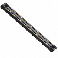


 工商网监
湘ICP备2023018690号
工商网监
湘ICP备2023018690号
