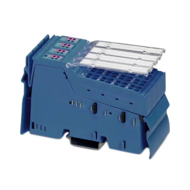
IB IL EX-IS DIO 4/NAM-PAC
Intrinsically safe Inline digital I/O terminal
for hazardous locations
Data sheet
2846_en_D
1
© PHOENIX CONTACT 2015-04-07
Description
2
The IB IL EX-IS DIO 4/NAM-PAC terminal is an intrinsically
safe, digital input/output unit for sensor and actuator connection directly into Zone 1, 0 or Class I, Division 2 (see
“Conformance/approvals” on page 4 for specific listings). It
also supports proximity sensors as per EN 60947-5-6
(NAMUR).
–
–
The terminal and accompanying intrinsically safe power
supply (IB IL EX-IS PWR IN-PAC) is installed in Zone 2 or a
safe area.
–
–
The terminal provides four independently configurable digital channels for digital inputs, such as dry contacts, NAMUR
sensors and optocouplers, and outputs, such as buzzers,
signal lamps, LEDs or solenoid valves.
–
–
–
–
–
Features
Four channels are configured independently of one
another as either an input or output channel
Four 8.2 V DC (loop-powered) inputs for connection of
digital sensors, such as dry contacts
Accepts NAMUR sensor inputs or sensors with
NAMUR network
Connection of sensors in 2-wire technology
Maximum permissible load current at each output
channel: 45 mA
Four digital outputs for connection of digital switches
Individual channel diagnostic indicators
Remote diagnostics via process data channel
-25… +60°C operating range
This data sheet is only valid in association with the IB IL SYS PRO UM E user manual or the Inline system manual
for your bus system.
The use of this terminal requires connection via the IB IL EX-IS PWR IN-PAC (Order No. 2869910). The data sheet
can be downloaded at phoenixcontact.com.
Make sure you always use the latest documentation.
It can be downloaded at phoenixcontact.com.
This data sheet is valid for all products listed on page 3.
�IB IL EX-IS DIO 4/NAM-PAC
1
Description.................................................................................................................................. 1
2
Features ..................................................................................................................................... 1
3
Ordering data.............................................................................................................................. 3
4
Technical data ............................................................................................................................ 3
5
Internal circuit diagram ............................................................................................................... 5
6
Electrical isolation ...................................................................................................................... 6
7
Local diagnostic and status indicators and terminal point assignment ....................................... 6
7.1
7.2
7.3
8
Safety regulations installation notes ......................................................................................... 7
8.1
8.2
8.3
9
Function identification..................................................................................................................................... 6
Local diagnostic and status indicators............................................................................................................ 6
Terminal point assignment for each connector .............................................................................................. 6
Special conditions for safe use....................................................................................................................... 7
Safety instructions ......................................................................................................................................... 7
FM compliance............................................................................................................................................... 8
Installation instructions ............................................................................................................... 8
9.1
9.2
Overview ........................................................................................................................................................ 8
Power budget ................................................................................................................................................. 9
10 Connection examples ................................................................................................................10
11 Programming data/configuration data........................................................................................11
11.1
11.2
INTERBUS .................................................................................................................................................. 11
Other bus systems ....................................................................................................................................... 11
12 Configuration and read/write via process data ...........................................................................11
12.1
12.2
2846_en_D
Output .......................................................................................................................................................... 11
Input data/diagnostics .................................................................................................................................. 12
PHOENIX CONTACT
2
�IB IL EX-IS DIO 4/NAM-PAC
3
Ordering data
Products
Description
Terminal with four digital channels; selectable as either input or output
500 kbps transmission speed; includes accessories (connectors and labeling
fields)
Documentation
Description
Type
Order No.
Pcs./Pkt.
IB IL EX-IS DIO 4/NAM-PAC
2869911
1
Type
Order No.
Pcs./Pkt.
User manual:
“Configuring and Installing the INTERBUS Inline Product Range”
IB IL SYS PRO UM E
2743048
1
User manual:
“Automation Terminals of the Inline Product Range”
IL SYS INST UM E
2698737
1
4
Technical data
General data
Housing dimensions (width x height x depth)
48.8 mm x 136.8 mm x 71.5 mm
Weight
204 g
Operating mode
Process data mode with 1 word
Transmission speed
500 kbps
Permissible temperature (operation)
-25°C to +60°C
Permissible temperature (storage/transport)
-25°C to +85°C
Permissible humidity (operation/storage/transport)
10% to 95%, according to DIN EN 61131-2
Permissible air pressure (operation/storage/transport)
70 kPa to 106 kPa (up to 3000 m above sea level)
Degree of protection
IP20 according to IEC 60529
Protection class
Class 3 according to VDE 0106, IEC 60536
Connection method
Spring-cage terminals
Conductor cross section
0.2 mm2 - 1.5 mm2 (solid or stranded), 24 - 16 AWG
Interface
Local bus
Data routing
Power consumption
Communications power UL
5V
Current consumption from UL
100 mA (typical)/120 mA (maximum)
I/O supply voltage UEX (nominal)
24 V DC
I/O supply voltage UEX (maximum)
28 V DC
Current consumption at UEX
90 mA (typical)/187 mA (maximum)
Total power consumption
1500 mW (typical)/2200 mW (maximum)
2846_en_D
PHOENIX CONTACT
3
�IB IL EX-IS DIO 4/NAM-PAC
Hazardous location ratings
Output
Input
Module supply Voltage UEX1
28 V DC
28 V DC
Voltage input Ui
0 V DC
0 V DC
Voltage output Uo
28 V DC
11.76 V DC
Current output Io
109 mA
137 mA
Power output Po
757 mW
401 mW
IIC
IIB
IIA
IIC
IIB
IIA
Capacitance Co2
0.083 µF
0.625 µF
2.15 µF
1.5 µF
9.9 µF
39 µF
Inductance Lo2
1.015 mH
3.045 mH
8.12 mH
1.52 mH
4.56 mH
21.1 mH
1
UEX = Um as listed in the SIRA Certification
2
The quoted entity parameters of Co and Lo are applicable for the distributed capacitance and inductance in cable. Where there is circuit capacitance or
inductance in the connected equipment (represented by Ci and Li respectively), then these values shall not exceed 50% of the quoted Co and Lo.
Supply of the module electronics and I/O through the bus coupler/power terminal
Connection method
Potential routing
Digital inputs
Number
4 (can also be configured as outputs)
Process data update of the channels
< 1 ms
Digital inputs (NAMUR)
Number
4 (can also be configured as outputs)
Input range
0 V to 10 V
Input resistance
300 k, approximately
Open circuit response
Goes to 0 V
Digital outputs
Number
4 (can also be configured as inputs)
Process data update of the channels
< 1 ms
Electrical isolation/isolation of the voltage areas
Common potentials
The UEX and GND have the same potential. FE is a separate potential area.
Error messages to the higher-level control or computer system
Failure of the internal I/O voltage supply
Yes, I/O error message sent to the bus coupler
Failure of or insufficient communications power UL
Yes, I/O error message sent to the bus coupler
Peripheral fault/user error
Yes, error message via the IN process data
Conformance/approvals
c
94/9/EC
EN 60079-0:2009
EN 60079-11:2007
EN 60079-15:2010
ATEX
IECEx
Sira 09ATEX2339X; Ex nA [ia Ga Da] IIC T4 Gc
IECEx SIR 10.0033X; Ex nA [ia Ga Da] IIC T4 Gc
X II 3(1)GD
UL/cUL
Class I, Div. 2, Groups A, B, C, D
FM
Class I, Div. 2, Groups A-G; Class I, Zone 2 AEx nA [ia] IIC T4
2846_en_D
PHOENIX CONTACT
4
�IB IL EX-IS DIO 4/NAM-PAC
5
Internal circuit diagram
OPC
(SUPI4)
Local Bus
GND
UL
GND
UL
5V
µP
EEPROM
±3.3 V
SUPERVISOR
µP
+24 V
8.2 V
24 V
+24 V (UEX)
Figure 1
DI1
DO1
DI2
DO2
DI3
DO3
DI4
DO4
UV1
US1
UV2
US2
UV3
US3
UV4
US4
Internal wiring of the terminal points
Key:
Protocol chip
OPC
Transistor
x x x
Power supply unit with electrical isolation
µ P
Microprocessor
X X X
Optocoupler
Electrically erasable programmable readonly memory
E E P R O M
Amplifier
S U P E R V IS O R
Microprocessor monitoring
Other symbols used are explained in the IB IL SYS PRO UM E user manual or in the Inline system manual for your
bus system.
2846_en_D
PHOENIX CONTACT
5
�IB IL EX-IS DIO 4/NAM-PAC
6
7.1
Electrical isolation
Local bus (IN)
Local bus (OUT)
OPC and
microprocessor
(SUPI 4 and MSP430)
UL (5 V DC)
UL (5 V DC)
28 V
UEX (28 V DC)
UEX (28 V DC)
Peripheral
interface
Electrical isolation
between area A
and B
A
B
Ex-Is Digital
Inputs/Outputs
Figure 2
7
Function identification
Color
Blue
Red
Blue (Frame)
7.2
Local diagnostic and status indicators
Des.
D
Local diagnostic and status
indicators and terminal point
assignment
IN
OUT
7.3
D
IN OUT
IN OUT
IN OUT
IN OUT
DIO EXi
Ex II 3(1) GD
Ex nA [ia Ga Da] IIC T4 Gc
SIRA 09ATEX2339X
IECEx SIR 10.0033X
Tamb=- 25°Ct o +60°C
IB IL EX-IS DIO 4/NAM-PAC
Order-No.: 2869911
HW/FW A / 1
Module-ID: 191
IN
IN
D
IN
DIO
IN
T
OU
T
OU
T
OU
T
OU
EX
Color
Green
0.5 Hz
2 Hz
4 Hz
Green (on)
Yellow (on)
Red (on)
Green (on)
Yellow (on)
Red (on)
FE potential
Electrical isolation of the individual function
areas
i
Meaning
Digital input
Digital output
Intrinsically safe
Terminal point assignment for each connector
Terminal
Points
1.1
1.2
0518
PHOENIX CONTACT GmbH&C
Flachsmarktstraße 8
32825 Blomberg, Germany
KG
1.3
1.4
2.1
2.2
2.3
2.4
Meaning
Diagnostics
Local bus stop
UEX low or off
Local bus failure
Input on and OK
Status (on = high)
Broken wire or overload
Output on and OK
Status (on = high)
Broken wire or overload
Signal
Assignment
Digital input for channel x
DIx
UVx (8.2 V) Initiator supply for digital input on
channel x
DOx
Digital output for channel x
GND
Ground
x = 1 to 4
1.1
1.2
1.3
1.4
Figure 3
2846_en_D
1.1
2.1
1.2
2.2
1.3
2.3
1.4
2.4
2.1
2.2
2.3
2.4
IB IL EX-IS DIO 4/NAM-PAC terminal with an
appropriate connector
PHOENIX CONTACT
6
�IB IL EX-IS DIO 4/NAM-PAC
8
Safety regulations installation
notes
For a list of terminals that are approved for the
potentially explosive areas of Zone 2, please refer
to the AH EN IL EX ZONE 2 application note.
Verify use by checking the label on the Inline
terminal and the packaging.
WARNING: Explosion hazard
The following conditions must be observed to
adhere to the ATEX 94/9/EC directive.
8.1
Special conditions for safe use
The module shall only be supplied from the IB IL EX-IS PWR
IN-PAC module.
If the module is installed in a zone 2 hazardous area, it shall
be housed in an enclosure that is coded Ex nA, Ex e, Ex d or
Ex p. If the module is installed in a zone 22 or 21 hazardous
area, it shall be housed in an enclosure that is coded Ex tD
or Ex t. For some types of enclosure, additional certification
is required to permit the installation of the module within the
enclosure. Reference should be made to the enclosure certificate. The installer shall ensure that the maximum ambient
temperature of the module, when installed, is not exceeded.
If the module is installed in a non-hazardous area, the enclosure or location shall provide suitable protection. This may
be either by the use of an enclosure approved for use in
zones 1, 2, 21, or 22 or otherwise meet the following requirements:
– Non-metallic enclosures must be capable of
withstanding the thermal endurance requirements of
IEC 60079-0 prior to impact and IP54 testing.
– Any enclosure must be capable of withstanding an
impact of 7J or the module is otherwise protected from
impact.
– The enclosure or location must provide an ingress
protection of at least IP54.
– If exposed to sunlight, non-metallic enclosures must be
capable of meeting the requirements of IEC 60079-0
clause 26.10 regarding resistance to light.
The installer is responsible for ensuring that the mounting of
the module does not reduce the segregation distances between different modules. There shall be a minimum of 6 mm
between any intrinsically safe terminals and other conductors or earthed metal, in accordance with IEC 6007914:2007 clause 12.2.3. In addition, there shall be a minimum
of 50 mm between the intrinsically safe terminals of the
module and any non-intrinsically safe terminals.
2846_en_D
When the module is mounted in a zoned area, live connection and disconnection of the module from the rail is only
permitted if the potentially explosive atmosphere is shown
to be absent.
Each of the four channels of the IB IL EX-IS DIO 4/
NAM-PAC (4x digital in or 4x digital out) shall be treated as
separate, intrinsically safe circuits.
The IB IL EX-IS DIO 4/NAM-PAC input and output circuits
may not be connected to the same equipment unless the
equipment maintains isolation between the circuits.
Each channel shares a common zero volts with the other
channels in the IB IL EX-IS DIO 4/NAM-PAC module as well
as other IB IL EX-IS DIO 4/NAM-PAC modules and non-isolated IB IL EX-IS…IO… modules connected to the same IB
IL EX-IS PWR IN-PAC (power supply) module. If the field
devices do not maintain 500 V AC isolation from earth/
ground, then all the non-isolated devices from the same IB
IL EX-IS PWR IN-PAC module shall be installed in a location
(such as the same vessel) where a difference in earth/
ground potential is unlikely to occur. If the field devices
maintain 500 V AC isolation from earth/ground, there is no
such limitation.
The quoted entity parameters of Co and Lo are applicable for
the distributed capacitance and inductance in cable. Where
there is circuit capacitance or inductance in the connected
equipment (represented by Ci and Lc respectively), these
values shall not exceed 50% of the quoted Co and Lo.
8.2
Safety instructions
WARNING:
The safety instructions must be read and
understood before installing and using this
equipment.
Installation instructions
The device is an associated equipment of the “intrinsically
safe” protection type and suitable for installation in zone 2.
Follow the installation instructions.
Installation, operation and maintenance may only be carried
out by qualified personnel.
Always remove power from Inline station before installing or
removing any Inline terminal.
Comply with the valid safety regulations (including national
safety regulations) for the installation and operation, accident prevention regulations, and the general rules and regulations pertaining to technology. The safety relevant data
may be derived from the operating instructions and the cer-
PHOENIX CONTACT
7
�IB IL EX-IS DIO 4/NAM-PAC
tificates (EC type examination certificate, possibly additional ratings).
WARNING:
Substitution of components will impair intrinsic
safety.
8.3
FM compliance
In addition to the previous statements, FM compliance requires that the module is mounted in an enclosure that
meets the requirements of ANSI/ISA 601010 and is installed
according to the mounting, spacing and segregation requirements of the enclosure for the ultimate application.
WARNING:
To prevent ignition of flammable or combustible
atmospheres, disconnect power before servicing.
Access to the circuits or substitution of components within
the device will impair intrinsic safety and is prohibited. Do
not repair the device yourself, but replace it with an equivalent device. Repairs may only be carried out by the manufacturer.
The IP20 degree of protection (IEC 60529/EN 60529) is intended for a clean and dry environment. Do not expose the
device to any mechanical or thermal influences that exceed
the limits described.
Intrinsic safety
9
Installation instructions
Always install the IB IL EX-IS... at the end of an Inline station.
If additional power is required, a new node must be installed. Intrinsically safe wiring must be installed separately
from non-intrinsically safe wiring (can’t be mixed within a
wire channel). A new IS power supply is required if the red
LED shows overloading.
9.1
Overview
Inline intrinsically safe IO terminals can be installed in a
standard Inline station and are supported by all major industrial networks. Basic and intrinsically safe wiring practices
need to be followed by the following concept.
When carrying out measurements on the intrinsically safe
side, it is imperative that you observe the relevant regulations regarding connecting intrinsically safe electrical equipment. Only use equipment approved for intrinsically safe circuits.
If the device was used in circuits that are not intrinsically
safe, it is forbidden to use it again in intrinsically safe circuits.
Label the device clearly as being not intrinsically safe.
Installation in zone 2
Observe the specified conditions for use in potentially explosive areas! Use a suitable housing of the minimum protection IP54 for the installation. Within this context observe
the requirements of IEC 60079-14/EN 60079-14, i.e., steel
housing with a wall thickness of 3 mm.
Do not connect any live cables/lines within the potentially
explosive area.
Only use IB IL EX-IS... modules of category 3G (ATEX 94/
9EG).
Potentially dust-explosive areas
The device is not designed for use in environments capable
of dust explosions.
Only make the connection to the intrinsically safe circuit in
potentially dust-explosive areas of zones 20, 21 and 22 if the
equipment connected to this circuit is certified for this zone
(e.g., category 1D, 2D or 3D).
2846_en_D
PHOENIX CONTACT
8
�IB IL EX-IS…
IB IL EX-IS…
IBSIL24BK-T/U
IB IL EX-IS PWR-IN
IB IL EX-IS DIO 4/NAM-PAC
Local Bus
OPC
GND
UL
7.5 V
5V
24 V
24 V
24 V
24 V
US
UEX
OUT
IN
UM
+
Fieldbus
Figure 4
-
UBK
Intrinsically safe Inline terminals power supply
A new IB IL EX-IS PWR IN-PAC supply is required if the red
LED on the power supply shows overloading. If additional
power is required, a new node must be installed.
9.2
Power budget
The IB IL EX-IS PWR IN-PAC provides power to the IB IL
EX-IS DIO 4/NAM-PAC terminal in two ways:
– 1000 mA is available for the logic functions (UL).
– 1000 mA is available for the I/O functions (UEX).
The number of terminals that can be powered by the IB IL
EX-IS PWR IN-PAC varies according to the type of terminal
and the number and type of I/O connections.
Based on the logic functions, the maximum number of terminals that can be connected is 10.
The IB IL EX-IS DIO 4/NAM-PAC terminal draws different
power depending on the type of connection. To determine
the number of I/O points that can be connected, refer to
Table 1.
2846_en_D
Table 1
UEX Current Draw
Terminal overhead
Output channel
Input channel
IB IL EX-IS DIO 4/NAM-PAC
20 mA
45 mA
10 mA
To calculate the power requirements of a system, list the
number and type of each connected point. From this list, determine the number and type of terminals required. Multiply
the number of each I/O point by the appropriate current draw
listed in Table 1.
Add the terminal overhead current for each terminal used.
The sum of the I/O point current draw and the terminal overhead current draw determines the total current draw from
the IB IL EX-IS PWR IN-PAC. The maximum current draw is
1000 mA.
Additional information and examples about power
budget calculation can be found on the Power
Supply data sheet.
PHOENIX CONTACT
9
�IB IL EX-IS DIO 4/NAM-PAC
10
Connection examples
Slot/
Channel
1
2
3
4
1.1 2.1
–
1.2 2.2
+
D
IN OUT
IN OUT
IN OUT
IN OUT
1.3 2.3
Zone 2
DIO EXI
1.1 2.1
3.1 4.1
5.1 6.1
7.1 8.1
1.2 2.2
3.2 4.2
5.2 6.2
7.2 8.2
1.3 2.3
3.3 4.3
5.3 6.3
7.3 8.3
1.4 2.4
3.4 4.4
5.4 6.4
7.4 8.4
1.4 2.4
Figure 7
Dry-contact input example
7.1 8.1
–
7.2 8.2
7.3 8.3
7.4 8.4
Figure 8
Digital input
at channel 1
Figure 5
+
OUT
IN 1
+8,2V
Zone 0, 1, 2
Zone 20, 21, 22
Digital output example
Digital output
at channel 4
Connection overview
1.1 2.1
–
1.2 2.2
+
1.3 2.3
1.4 2.4
Figure 6
2846_en_D
NAMUR input example
PHOENIX CONTACT
10
�IB IL EX-IS DIO 4/NAM-PAC
11
Programming data/configuration data
11.1
INTERBUS
ID code
0xBFhex (191dec)
Length code
01hex
Input address area
1 words
Output address area
1 words
Parameter channel (PCP)
0
Register length (bus)
1 words
11.2
Other bus systems
For the programming data/configuration data of
other bus systems, please refer to the
corresponding electronic device data sheet
(e.g., GSD, EDS).
12
Configuration and read/write via process data
Below are the details of the process data word.
12.1
Output
The process data word is used for configuring the channels and writing output data.
Bit
Assignment
OUT1
Byte 1
15
14
13
12
11
10
9
8
7
6
Command 0x5
Out Out Out Out Config Ch
ch 4 ch 3 ch 2 ch 1
4
Byte 0
5
4
3
2
Config Ch Config Ch
3
2
1
0
Config Ch
1
Placing command code 0x5 in bits 12 to 15 allows configuration of channels 1 through 4. Command code 0x5 is not required
to set output bits 8 to 11, but can be used. Once configured, however, it is suggested that output bits 15 to 12 are set to 0x0
to avoid unintentional configuration of the module.
The default refresh rate is 10 ms.
Parameters for configuration
Channel 1 to channel 4, bits 0 to 7
Code (bin)
00
01
10
11
Format
Disable channel
Input
Output
Standard digital input (non-NAMUR)
Parameters for digital output
Channel 1 to channel 4, bits 8 to 11
0
Logic low
1
Logic high
2846_en_D
PHOENIX CONTACT
11
�IB IL EX-IS DIO 4/NAM-PAC
12.2
Input data/diagnostics
Reading back the input and diagnostic information.
Bit
Assignment
IN1
Byte 1
15
14
13
12
11
10
9
8
7
6
Command Mirror 0x5
In
In
In
In
Diag Ch 4
ch 4 ch 3 ch 2 ch 1
Byte 0
5
4
3
2
Diag Ch 3 Diag Ch 2
1
0
Diag Ch 1
Input data (bits 8-11) for channels are valid only if the corresponding channels are configured for input.
For all unconfigured channels, the diagnostic info will return “Invalid Level”.
2846_en_D
PHOENIX CONTACT
12
�IB IL EX-IS DIO 4/NAM-PAC
Write 0101 (bin)
to bits 12 to 15 in
the output word
Input bits 12 to
15 match output
bits?
No
Wait for input bits 12
to 15 to equal output
bits 12 to 15
Yes
Is channel X
used for a
Namur input?
Yes
Write 01 (bin) to
channel X
configuration bits
No
Is channel X
used for a digital
output?
Yes
Write 10 (bin) to
channel X
configuration bits
Yes
Write 11 (bin) to
channel X
configuration bits
Yes
Read input data
or write output
data
No
Is channel X
used for a
standard input?
No
All channels
configured?
No
Repeat for channel
X+1
Figure 9
2846_en_D
Diagnostic flowchart
PHOENIX CONTACT
13
�IB IL EX-IS DIO 4/NAM-PAC
Diagnostics
Channel 1 to channel 4, bits 0 to 7 (applies to NAMUR sensors only).
Code (bin)
00
01
10
11
2846_en_D
Format
No error
Short
Open
Invalid level
PHOENIX CONTACT GmbH & Co. KG • 32823 Blomberg • Germany
www.phoenixcontact.com
14
�


 工商网监
湘ICP备2023018690号
工商网监
湘ICP备2023018690号
