SMT POWER INDUCTORS
Shielded Drum Core - P1167NL Series
Height: 4.8mm Max
Footprint: 7.5mm x 7.5mm Max
Current Rating: up to 3.5A
Inductance Range: 1.8µH to 750µH
Electrical Specifications @ 25°C — Operating Temperature -40°C to +130°C
Saturation 6
Inductance
Inductance
DCR (m Ω )
Part 2,3
Irated 5
@0A DC
@Irated
Current
Number
(A
DC )
(μH ±20%)
(μH) MIN
TYP
MAX
-25% (A)
P1167.272NL
2.7*
1.8
3.5
13
16
3.5
P1167.362NL
3.6*
2.3
3.1
15
20
3.1
P1167.452NL
4.5*
2.9
2.6
25
30
2.9
P1167.542NL
5.4*
3.5
2.5
27
33
2.7
P1167.632NL
6.3*
4.1
2.4
30
35
2.5
P1167.103NL
10
7.5
2.0
42
50
2.1
P1167.123NL
12
9.0
1.9
46
57
1.9
P1167.153NL
15
11.3
1.7
53
66
1.7
P1167.183NL
18
13.5
1.5
59
73
1.5
P1167.223NL
22
16.5
1.4
87
105
1.4
P1167.273NL
27
20.3
1.2
100
130
1.2
P1167.333NL
33
24.8
1.1
139
170
1.1
P1167.393NL
39
29.3
1.0
156
200
1.0
P1167.473NL
47
35.3
0.94
173
220
0.94
P1167.563NL
56
42
0.86
225
270
0.86
P1167.683NL
68
51
0.78
251
310
0.78
P1167.823NL
82
61.5
0.7
282
350
0.7
P1167.104NL
100
75
0.63
317
390
0.63
P1167.124NL
120
90
0.57
418
530
0.57
P1167.154NL
150
113
0.52
497
610
0.52
P1167.184NL
180
135
0.47
635
820
0.47
P1167.224NL
220
165
0.43
745
930
0.43
P1167.274NL
270
203
0.39
840
1040
0.39
P1167.334NL
330
248
0.35
1162
1470
0.35
P1167.394NL
390
293
0.32
1237
1570
0.32
P1167.474NL
470
353
0.29
1688
2180
0.29
P1167.564NL
560
420
0.26
2240
2960
0.26
P1167.684NL
680
510
0.23
2402
3180
0.23
P1167.824NL
820
615
0.21
2702
3500
0.21
P1167.105NL
1000
750
0.19
3703
4930
0.19
* I n d u c t a n c e a t 0 A DC t o l e r a n c e o n i n d i c a t e d p a r t n u m b e r s i s ± 3 0 % ; t o l e r a n c e i s ± 2 0 % o n a l l o t h e r p a r t s .
Schematic
Mechanical
.197
5,00
.177 MAX
4,50
.297
7,54 2
MAX
XXX
.297 MAX
7,54
Weight . . . . . . . . 0.9 grams
Tape & Reel . . . . . . 900/reel
.083
2,11
1
1
SUGGESTED PAD LAYOUT
1
.083
2,11
2
.197
5,00
.287
7,29
.220
5,60
.301
7,65
Heating 7
Core Loss 8
SRF
Current
Factor
(MHz)
+40°C(A)
(K2)
3.6
590
>40
3.4
690
>40
2.6
770
>40
2.5
840
>40
2.4
900
36
2.0
1100
26
1.9
1200
24
1.8
1300
20
1.7
1400
18
1.4
1700
17
1.3
1800
15
1.1
2000
13
1.0
2200
12
1.0
2400
10
0.86
2600
9.2
0.81
2900
8.8
0.77
3200
8.0
0.72
3500
6.2
0.63
3900
6.1
0.58
4300
5.6
0.51
4800
4.5
0.47
5200
4.3
0.44
5700
3.8
0.38
6400
3.0
0.37
6900
2.8
0.31
7600
2.6
0.27
8300
2.4
0.26
9300
2.1
0.25
10000
2.0
0.21
11000
1.8
NOTES FROM TABLE: (See page 43)
2
.472
12,00
Dimensions: Inches
mm
Unless otherwise specified,
all tolerances are ± .010
0,25
.630
16,00
TAPE & REEL LAYOUT
USA 858 674 8100 • Germany 49 7032 7806 0 • Singapore 65 6287 8998 • Shanghai 86 21 54643211 / 2 • China 86 755 33966678 • Taiwan 886 3 4641811
www.pulseeng.com
35
SPM2007 (11/07)
�SMT POWER INDUCTORS
Shielded Drum Core Series
Notes from Tables (pages 27 - 42)
1. Unless otherwise specified, all testing is made at
100kHz, 0.1VAC.
8. In high volt*time (Et) or ripple current applications, additional heating in the component can occur due to core
losses in the inductor which may necessitate derating
the current in order to limit the temperature rise of the
component. In order to determine the approximate total
loss (or temperature rise) for a given application, both
copper losses and core losses should be taken into
account.
2. Optional Tape & Reel packaging can be ordered by
adding a "T" suffix to the part number (i.e. P1166.102NL
becomes P1166.102NLT). Pulse complies with industry
standard Tape and Tape & Reel specification EIA481.
3. The "NL" suffix indicates an RoHS-compliant part
number. Non-NL suffixed parts are not necessarily
RoHS compliant, but are electrically and mechanically
equivalent to NL versions. If a part number does not
have the "NL" suffix, but an RoHS compliant version is
required, please contact Pulse for availability.
Estimated Temperature Rise:
Trise = [Total loss (mW) / K0].833 (oC )
4. Temperature of the component (ambient plus
temperature rise) must be within specified operating
temperature range.
Total loss = Copper loss + Core loss (mW)
5. The rated current (Irated) as listed is either the saturation current or the heating current depending on which
value is lower.
Copper loss = IRMS2 x DCR (Typical) (mW)
Irms = [IDC2 + ΔI2/12]1/2 (A)
6. The saturation current, Isat, is the current at which
the component inductance drops by the indicated
percentage (typical) at an ambient temperature of
25°C. This current is determined by placing the
component in the specified ambient environment and
applying a short duration pulse current (to eliminate
self-heating effects) to the component.
Core loss = K1 x f (kHz)1.23 x Bac(Ga)2.38 (mW)
Bac (peak to peak flux density) = K2 x ΔI (Ga)
[= K2/L(µH) x Et(V-µSec) (Ga)]
where f varies between 25kHz and 1MHz, and Bac is
less than 2500 Gauss.
Part No.
PG0085/86
PG0087
PG0040/41
P1174
PF0601
PF0464
PF0465
P1166
P1167
PF0560NL
P1168/69
P1170/71
P1172/73
PF0552NL
PF0553NL
Trise Factor
(K0 )
2.3
5.8
0.8
0.8
4.6
3.6
3.6
1.9
2.1
5.5
4.8
4.3
5.6
8.3
7.1
Core Loss Factor
(K1)
5.29E-10
15.2E-10
2.80E-10
6.47E-10
14.0E-10
24.7E-10
33.4E-10
29.6E-10
42.2E-10
136E-10
184E-10
201E-10
411E-10
201E-10
411E-10
Core Loss / K1 (mW)
7. The heating current, Idc, is the DC current required
to raise the component temperature by the indicated
delta (approximately). The heating current is
determined by mounting the component on a
typical PCB and applying current for 30 minutes. The
temperature is measured by placing the thermocouple
on top of the unit under test.
K2 is a core size and winding dependant value and
is given for each p/n in the proceeding datasheets.
K0 & K1 are platform and material dependant constants
and are given in the table below for each platform.
CoreLoss/K1 Vs Flux Density
3.00E+10
100KHz
2.50E+10
200KHz
2.00E+10
300KHz
1.50E+10
400KHz
1.00E+10
500KHz
700KHz
0.50E+10
0
1.0MHz
0
500
1000
1500
DB (Gauss)
2000
2500
where DB = K2 x DI [= K2/L(µH) x Et(V-µSec)]
Take note that the component's temperature rise varies depending on the system condition. It is suggested that the
component be tested at the system level, to verify the temperature rise of the component during system operation.
USA 858 674 8100 • Germany 49 7032 7806 0 • Singapore 65 6287 8998 • Shanghai 86 21 54643211 / 2 • China 86 755 33966678 • Taiwan 886 3 4641811
www.pulseeng.com
43
SPM2007 (11/07)
�
很抱歉,暂时无法提供与“P1167.823NLT”相匹配的价格&库存,您可以联系我们找货
免费人工找货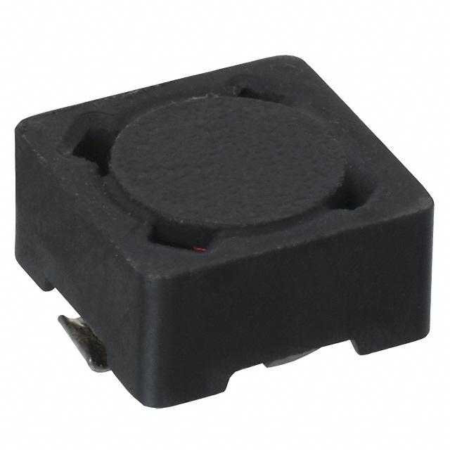


 工商网监
湘ICP备2023018690号
工商网监
湘ICP备2023018690号
