Network PBU
RF Chip Inductors
Wire-Wound-0603 Series
�Wire Wound RF Chip Inductors
0603CD Series
Wire wound ceramic core construction
High Q values
High self resonant frequency
Temperature Range -40°C to +125°C
Industry 0603 (1608) size and surface
mount land pattern
100% Tin Solder Termination
Electrical Specifications @ 25°C - Operating Temperature Range -40oC to +125oC
Part Number
Tolerance +/-2%
Part Number
Tolerance +/-5%
Inductance1
(nH)
Q2
(MIN)
SRF 3
(MHz MIN)
RDC 4
(Ω MAX)
IDC 5
(mA MAX)
N/A
PE-0603CD010JTT
1.7 @ 250MHz
16 @ 250MHz
>6000
0.050
700
N/A
PE-0603CD1N8JTT
1.8 @ 250MHz
16 @ 250MHz
>6000
0.045
700
N/A
PE-0603CD2N2JTT
2.2 @ 250MHz
18 @ 250MHz
>6000
0.011
700
PE-0603CD3N3GTT
PE-0603CD3N3JTT
3.3 @ 250MHz
35 @ 250MHz
>6000
0045
700
PE-0603CD3N6GTT
PE-0603CD3N6JTT
3.6 @ 250MHz
20 @ 250MHz
>6000
0.070
700
PE-0603CD030GTT
PE-0603CD030JTT
3.9 @ 250MHz
20 @ 250MHz
>6000
0.080
700
PE-0603CD4N3GTT
PE-0603CD4N3JTT
4.3 @ 250MHz
20 @ 250MHz
>6000
0.102
700
PE-0603CD040GTT
PE-0603CD040JTT
4.55 @ 250MHz
20 @ 250MHz
5800
0.106
700
PE-0603CD4N7GTT
PE-0603CD4N7JTT
4.7 @ 250MHz
20 @ 250MHz
5800
0.116
700
PE-0603CD5N1GTT
PE-0603CD5N1JTT
5.1 @ 250MHz
20 @ 250MHz
2700
0.108
700
PE-0603CD5N6GTT
PE-0603CD5N6JTT
5.6 @ 250MHz
25 @ 250MHz
5500
0.108
700
PE-0603CD6N2GTT
PE-0603CD6N2JTT
6.2 @ 250MHz
25 @ 250MHz
5800
0.110
700
PE-0603CD060GTT
PE-0603CD060JTT
6.68 @ 250MHz
25 @ 250MHz
5800
0.110
700
PE-0603CD6N8GTT
PE-0603CD6N8JTT
6.8 @ 250MHz
27 @ 250MHz
5800
0.110
700
PE-0603CD7N5GTT
PE-0603CD7N5JTT
7.5 @ 250MHz
28 @ 250MHz
4800
0.150
700
PE-0603CD080GTT
PE-0603CD080JTT
8.2 @ 250MHz
30 @ 250MHz
4600
0.120
700
PE-0603CD8N7GTT
PE-0603CD8N7JTT
8.7 @ 250MHz
28 @ 250MHz
4600
0.109
700
PE-0603CD9N5GTT
PE-0603CD9N5JTT
9.5 @ 250MHz
28 @ 250MHz
5400
0.135
700
PE-0603CD100GTT
PE-0603CD100JTT
10.0 @ 250MHz
30 @ 250MHz
4800
0.130
700
PE-0603CD110GTT
PE-0603CD110JTT
11.0 @ 250MHz
30 @ 250MHz
4000
0.086
700
PE-0603CD120GTT
PE-0603CD120JTT
12.0 @ 250MHz
50 @ 250MHz
4000
0.130
700
PE-0603CD130GTT
PE-0603CD130JTT
13.0 @ 250MHz
45 @ 250MHz
3600
0.106
700
PE-0603CD150GTT
PE-0603CD150JTT
15.0 @ 250MHz
45 @ 250MHz
4000
0.170
700
PE-0603CD160GTT
PE-0603CD160JTT
16.0 @ 250MHz
45 @ 250MHz
3300
0.170
700
PE-0603CD180GTT
PE-0603CD180JTT
18.0 @ 250MHz
35 @ 250MHz
3100
0.170
700
2
PulseElectronics.com
WC709.D (02/21)
�Wire Wound RF Chip Inductors
0603CD Series
Electrical Specifications @ 25°C - Operating Temperature Range -40°C to +125°C (continued)
Part Number
Tolerance +/-2%
Part Number 6
Tolerance +/-5%
Inductance 1
(nH)
Q2
(MIN)
SRF 3
(MHz MIN)
RDC 4
(Ω MAX)
IDC 5
(mA MAX)
PE-0603CD220GTT
PE-0603CD220JTT
22.0 @ 250MHz
35 @ 250MHz
3000
0.19
700
PE-0603CD270GTT
PE-0603CD270JTT
27.0 @ 250MHz
35 @ 250MHz
2800
0.22
600
PE-0603CD300GTT
PE-0603CD300JTT
30.0 @ 250MHz
37 @ 250MHz
2250
0.44
600
PE-0603CD330GTT
PE-0603CD330JTT
33.0 @ 250MHz
35 @ 250MHz
2300
0.22
600
PE-0603CD360GTT
PE-0603CD360JTT
36.0 @ 250MHz
37 @ 250MHz
2080
0.25
600
PE-0603CD390GTT
PE-0603CD390JTT
39.0 @ 250MHz
35 @ 250MHz
2200
0.25
600
PE-0603CD430GTT
PE-0603CD430JTT
43.0 @ 250MHz
35 @ 200MHz
2000
0.28
600
PE-0603CD470GTT
PE-0603CD470JTT
47.0 @ 250MHz
35 @ 100MHz
2000
0.28
600
PE-0603CD560GTT
PE-0603CD560JTT
56.0 @ 250MHz
35 @ 200MHz
1900
0.31
600
PE-0603CD680GTT
PE-0603CD680JTT
68.0 @ 250MHz
35 @ 200MHz
1700
0.34
600
PE-0603CD720GTT
PE-0603CD720JTT
72.0 @ 250MHz
34 @ 150MHz
1700
0.49
400
PE-0603CD820GTT
PE-0603CD820JTT
82.0 @ 250MHz
34 @ 150MHz
1700
0.54
400
PE-0603CD101GTT
PE-0603CD101JTT
98.5 @ 250MHz
34 @ 150MHz
1400
0.58
400
PE-0603CDR10GTT
PE-0603CDR10JTT
100 @ 250MHz
34 @ 150MHz
1400
0.58
400
PE-0603CD111GTT
PE-0603CD111JTT
110 @ 250MHz
33 @ 150MHz
1300
0.61
300
PE-0603CD121GTT
PE-0603CD121JTT
120 @ 250MHz
32 @ 150MHz
1300
0.65
300
PE-0603CD151GTT
PE-0603CD151JTT
150 @ 250MHz
28 @ 150MHz
990
0.92
280
PE-0603CD181GTT
PE-0603CD181JTT
180 @ 250MHz
25 @ 100MHz
990
1.25
240
PE-0603CD201GTT
PE-0603CD201JTT
200 @ 250MHz
25 @ 100MHz
900
1.98
240
PE-0603CD221GTT
PE-0603CD221JTT
220 @ 250MHz
25 @ 100MHz
900
1.90
200
PE-0603CD271GTT
PE-0603CD271JTT
270 @ 250MHz
24 @ 100MHz
860
2.30
170
PE-0603CD331GTT
PE-0603CD331JTT
330 @ 250MHz
22 @ 100MHz
500
2.30
150
PE-0603CD391GTT
PE-0603CD391JTT
390 @ 250MHz
20 @ 100MHz
350
2.90
130
6
Notes:
1. Inductance measured using a HP4286A RF Impedance Analyzer. (Please note that
inductance information is not stamped on part, because of the extremely small size).
2. Q measured using a HP4291A RF Impedance Analyzer with a HP16193A Test Fixture.
3. SRF measured using a HP8753C Network Analyzer.
4. RDC measured using a Valhalla Scientific model 4100 ATC Digital
Ohmeter.
5. Based on a 15°C maximum temperature rise
- see also specific application note on operation temperature
6. Check ordered tolerance band carefully:
To order a +/-2% tolerance band the ordering code ends with "GTT"
while any +/-5% tolerance band ends with "JTT" .
Specific Application note on operational temperature:
1. Operating Temperature range -40°C to +125°C includes a +40°C self rise above +85°C ambient.
2. Part temperature should not exceed +125°C under worst case conditions
Circuit design, variability and hot spot, component placement, PWB trace size and thickness, airflow and other cooling provisions all affect the part temperature.
Part temperature should be verified in the end applications
3
PulseElectronics.com
WC709.D (02/21)
�Wire Wound RF Chip Inductors
0603CD Series
Typical Inductance vs Frequency
Typical Q vs Frequency
200
120
100
150
Q Factor
Inductance (nH)
175
125
100
80
60
75
40
50
20
25
0
100
10
1,000
Frequency (MHz)
10,000
0
10
100
1,000
Frequency (MHz)
10,000
Mechanical
1
Weight: ..................0.008 grams
Dimensions:
Inches
mm
Unless otherwise specified,
all tolerances are ± 0.10
0,25
4
PulseElectronics.com
WC709.D (02/21)
�Wire Wound RF Chip Inductors
0603FT Series
Wire wound ferrite core construction
High Impedance Values for suppression
High self resonant frequency
Temperature Range -40°C to +125°C
Industry standard 0603 (1608) size and
surface mount land pattern
100% Tin Solder Termination
Electrical Specifications @ 25°C - Operating Temperature Range -40°C to +125°C
Part Number
Tolerance +/-10%
Inductance
(uH)
Typical
Impedance
SRF 3
(MHz MIN)
RDC 4
(Ω MAX)
IDC 5
(mA MAX)
PE-0603FT470KTT
0.047 @ 7.9MHz
20 @ 100MHz
1370
0.11
850
PE-0603FT101KTT
0.100 @ 7.9MHz
50 @ 100MHz
1370
0.11
850
PE-0603FT221KTT
0.220 @ 7.9MHz
100 @ 100MHz
850
0.20
650
PE-0603FT471KTT
0.470 @ 7.9MHz
300 @ 100MHz
670
0.37
470
PE-0603FT681KTT
0.680 @ 7.9MHz
800 @ 100MHz
520
0.77
310
PE-0603FT102KTT
1.00 @ 7.9MHz
1000 @ 100MHz
410
0.94
280
PE-0603FT272KTT
2.70 @ 7.9MHz
600 @ 25MHz
70
1.60
210
PE-0603FT682KTT
6.80 @ 7.9MHz
1000 @ 25MHz
40
4.00
130
PE-0603FT822KTT
8.20 @ 2.5MHz
600 @ 25MHz
40
4.50
110
PE-0603FT103KTT
10.0 @ 2.5MHz
800 @ 10MHz
30
5.00
100
PE-0603FT153KTT
15.0 @ 2.5MHz
1000 @ 10MHz
20
9.50
90
PE-0603FT223KTT
22.0 @ 2.5MHz
2500 @ 10MHz
20
11.40
70
6
1
Notes:
1. Inductance measured using a HP4286A RF Impedance Analyzer. (Please note that
inductance information is not stamped on part, because of the extremely small size).
2. Q measured using a HP4291A RF Impedance Analyzer with a HP16193A Test Fixture.
3. SRF measured using a HP8753C Network Analyzer.
4. RDC measured using a Valhalla Scientific model 4100 ATC Digital Ohmeter.
5. Based on a 15°C maximum temperature rise.
Mechanical
5
05/013
Weight: ..................0.008 grams
Dimensions:
Inches
mm
Unless otherwise specified,
all tolerances are ± 0.10
0,25
5
PulseElectronics.com
WC709.D (02/21)
�Wire Wound RF Chip Inductors
0603FT Series
Typical Inductance vs Frequency
40
Typical Impedance vs Frequency
22.0uH
22uH
5
470nH
)
25
1,000
I edance (
Inductance (uH)
2.7uH
10,000
0
20
15
10
47nH
100
10
5
100
10
Frequency (MHz)
1
1
10
1,000
100
Frequency (MHz)
Tape and Reel Specifications
Series
Parts per Reel
0603CD
0603FT
2000
Packing Moisture Level = MSL 1 - Storage Temperature - 40oC to +125oC
Reels Dimensions (mm)
Tape Dimensions (mm)
A
B
C
D
E
W
P1
P2
P3
H
T
178
2.1
0.3
50
13
14.4
8.4
8
2
4
4
Notes:
P1, P2 and P3 are same for all chip inductor series. Keeping the same dimensions for guide hole and pocket pitch (P1), pocket pitch (P2), guide hold pitch (P3) and tape width (8mm) for all series, enables
the packaging machine to maintain the same settings while changing models. The only difference between the series are the parts per reel which contributes to a different length of tapes/reel per model.
6
PulseElectronics.com
WC709.D (02/21)
�Wire Wound RF Chip Inductors
PERFORMANCE TESTING
Electrical Testing
Storage and Operating
Temperature Range:
-40°C to +125°C
Inductors are subjected to the extremes for 48 hours.
Then tested at 25°C
Thermal:
-40°C to +85°C
Inductors are subjected to 30 cycles for 30 minutes at
each extreme.
Then tested at 25°C
Moisture Resistance 240
Hours at 70°C
Inductors are subjected to 10 cycles of 24 hours at 90
to 95% relative humidity
Then tested at 24°C
Operating Life
Inductors are subjected to 1000 hours at
85°C with 85% Relative Humidity with the rated
current applied
There shall be no deformation or change in appearance
Inductance shall not change by more than ±5%
Q values shall not change by more than ±10%
There shall be no Damaged, Open
or Shorted Windings
Electrical Testing
Temperature Range:
Inductors are subjected to the following:
Use a solder pot at 260°C, with RMA Flux. Each termination
is immersed in 63Sn/37Pb molten solder for 4 to 6 seconds.
There shall be no deformation or change in appearance
Inductance shall not change by more than ±5%
Q values shall not change by more than ±10%
Recommended Solder Heat
Resistance Profile
Physical Specifications
Vibration (Random)
Samplers are subjected to random
vibrations as per NAVMAT P9492
Mechanical Shock
Inductors are subjected to one half sine wave
pulse (8700 g's for 0.3ms) in each directional axis
for a total of 18 shocks
Moisture Resistance
Reflow Inductors on to test pads using 63Sn/37 Pb
solder paste
(IR Reflow profile = 200 oC for 30 seconds or peak
235 oC for 20 seconds)
There shall be no deformation or change in appearance
Inductance shall not change by more than ±5%
Q values shall not change by more than ±10%
Pulse Jack
The inductors shall withstand a minimum force
of 1000 g's in any direction using a
dynamometer force guage
For More Information:
Americas - prodinfonetworkamericas@pulseelectronics.com | Europe - comms-Apps-Europe@pulseelectronics.com | Asia - prodinfonetworkapac@pulseelectronics.com
Performance warranty of products offered on this data sheet is limited to the parameters specified. Data is subject to change without notice. Other brand and product names mentioned herein may be
trademarks or registered trademarks of their respective owners. © Copyright, 2020. Pulse Electronics, Inc. All rights reserved.
7
PulseElectronics.com
WC709.D (02/21)
�
很抱歉,暂时无法提供与“PE-0603CD470JTT”相匹配的价格&库存,您可以联系我们找货
免费人工找货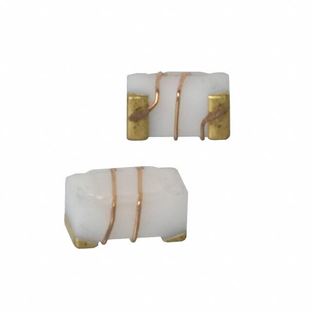


 工商网监
湘ICP备2023018690号
工商网监
湘ICP备2023018690号

