RF Chip Inductor Guide
Wire Wound and Multi-Layer - 0402, 0603, 0805, 1008
Pulse Electronics - leading supplier of magnetics for consumer applications
�RF CHIP INDUCTORS
Pulse Electronics Networking’s range of chip technology based products include inductors,
chokes and suppression beads in a variety of materials, sizes and values providing the optimum
performance fit for todays challenging circuit designs.
This short selection guide provides a starting point in the design process for choosing the right
sized product and solution for common and differential noise filtering and EMI suppression on signal,
data and power lines.
The products are split in to the following main family categories:
RF Inductors:
The ceramic core “CD” wire wound series offers four sizes for use filtering at High RF Frequency
with high Q and are available in either +/-5% or +/-2% tolerances bands. Available in a selection of
values from 1.0nH to 4.7uH and a wide operating temperature range from –40°C to +125°C.
The ferrite core “FT” wire wound series offers three sizes with higher inductance in each size than both
the ceramic and multi-layer families and support a +/-5% tolerance band. Available in a selection of
values from 22nH to 68.0uH and a wide operating temperature range from –40°C to +125°C.
Multi-Layer Inductors:
The "CL" monolithic ceramic series offers four sizes with low DC resistance and high Q, in the case of
the "0402CL" series. This series supports a wider operating temperature range from –55°C to +125°C
and are available in selected inductance values from 1.0nH to 6.3nH or 6.8nH to 120nH in +/-0.3nH and
+/-5% tolerances bands respectively.
The larger “CLH” series are a magnetically shielded, ceramic monolithic range and offer low DC
resistance for higher DC bias current handling for Power Lines and Point of Load Inductors. Available in
a selection of values from 0.47uH to 4.7uH and operating temperature range –40°C to +125°C.
Wire Wound Chip Inductors
Multi-Layer Chip Inductors
PART NUMBER LEGEND
PE
0805 CD
121 K T T
INDUCTANCE (μH)
PACKAGE STYLE
(0402, 0603, 0805, 1008)
Representative of
the inductance value
CORE MATERIAL
TOLERANCE
CD = Ceramic (Alumina) Standard Range
FT = Ferrite (High Inductance) Range
CL = Multi-Layer (Unshielded) Range
CLH = Multi-Layer (Shielded) Range
G = ±2%
J = ±5%
K = ±10%
TERMINATION
T or S = TIN PLATING
PACKAGING
Tape & Reel: 7" (178mm)
Size
PCs/Reel
S = 0.3nH or ±20%
Note: depends on the size and construction
2
PulseElectronics.com
WC720.A (04/21)
0402
0603 0805
1008
3000 2000 2000
1600
�RF CHIP INDUCTORS
PRODUCT APPLICATIONS
Wire wound RF inductors are designed on miniature ceramic or ferrite core bases and are used
for applications with frequencies mainly >50MHz. They exhibit low inductance and high Q values, or
on ferrite cores, for lower frequencies, the flux linkage between the turns of the coil dramatically
increase the inductance value for the same size.
Inductors at low frequencies conform to the idea path - see the curves below, but then soon
migrate as the reactance (XL) increases much faster than the inductance until it reaches its parallel
resonant frequency (Fr) . Above Fr and the component behaves in a capacitive manor and reactance
drops sharply. This can also be seen in the published performance curves for Q versus frequency. They
also gives an indication to suppression performance, since Q factor is the ratio of Reactance (XL) over
series resistance (Rs)
Idea
Ind c
(
Fr
ac
Ind c e
a p ac e
a
Impedance (XL
Fr
SRF
SRF
e enc (
e enc (
When selecting an RF inductor for real life applications the working or central frequency (Fc)
should be a magnitude of 10 below the listed SFR and preferably not more then half the Fr value.
Another key factor when selecting RF or miniature power line inductors, is the current handling
capability as the inductance droops or "derates" with increasing current and is dissipated as heat which
may cause unexpected performance issues over time. These parts can also be used for suppression as
well as filtering as they exhibit high impedances at 100MHz
Full Data sheets containing the whole range can be downloaded by clicking on the highlighted links in the table below
INDUCTANCE RANGE SELECTOIN FOR CERAMIC, FERRITE AND MULTI-LAYER SERIES INDUCTORS
Part Number
Size
Construction
Inductance Range
PE-0402CD
0402
Wirewound Ceramic
1.0 to 120
PE-0402FT
0402
Wirewound Ferrite
22 to 560
PE-0603CD
0603
Wirewound Ceramic
1.7 to 390
PE-0603FT
0603
Wirewound Ferrite
47 to 22,000
PE-0805CD
0805
Wirewound Ceramic
3.3 to 1,200
PE-0805FT
0805
Wirewound Ferrite
1,000 to 68,000
PE-1008CD
1008
Wirewound Ceramic
10 to 4,700
PE-0402CL
0402
Multi-layer Ceramic
1.0 to 120
PE-0603CLH
0603
Multi-layer Ceramic
220 to 2,200
PE-0805CLH
0805
Multi-layer Ceramic
470 to 4,700
PE-1008CLH
1008
Multi-layer Ceramic
470 to 4,700
3
1n
PulseElectronics.com
10 n
Inductance (xH)
100 n
1u
WC720.A (04/21)
10 u
100 u
�For More Information:
Americas - prodinfonetworkamericas@pulseelectronics.com | Europe - comms-Apps-Europe@pulseelectronics.com | Asia - prodinfonetworkapac@pulseelectronics.com
Performance warranty of products offered on this data sheet is limited to the parameters specified. Data is subject to change without notice. Other brand and product names mentioned herein may be
trademarks or registered trademarks of their respective owners. © Copyright, 2021. Pulse Electronics, Inc. All rights reserved.
4
PulseElectronics.com
WC720.A (04/21)
�
很抱歉,暂时无法提供与“PE-1008CM102KTT”相匹配的价格&库存,您可以联系我们找货
免费人工找货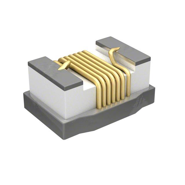


 工商网监
湘ICP备2023018690号
工商网监
湘ICP备2023018690号
