SMF4734AV
THRU
SMF4771AV
ZENER DIODES
FEATURES
* Silicon Planar Power Zener Diodes
* For use in stabilizing and clipping circuits with high power rating.
* These diodes are also available in the MELF case with type
designation ZM4728 thru ZM4764
* P/N suffix V means AEC-Q101 qualified, e.g:SMF4734AV
* P/N suffix V means Halogen-free
SOD-123FL
Cathode Band
Top View
1.0
* Case:SOD-123FL molded plastic body
* Mounting position: Any
* Weight: 0.064 gram
0.2
1.8 ± 0.1
MECHANICAL DATA
1.3 ± 0.15
0.20 0.10
• .1
2.8• 0
0.6 0.25
MAXIMUM RATINGS AND ELECTRICAL CHARACTERISTICS
o
Ratings at 25 C ambient temperature unless otherwise specified.
Resistive or inductive load.
3.7• 0
• .2
Dimensions millimeters
MAXIMUM RATINGS (@ TA=25 OC unless otherwise noted)
RATINGS
SYMBOL
VALUE
UNITS
1.0
Watts
ESD Voltage per IEC61000-4-2(Air)
Ptot
VESD
±30
KV
ESD Voltage per IEC61000-4-2(Contact)
VESD
±30
KV
TJ
-65 to + 150
0
C
T STG
-65 to + 150
0
C
SYMBOL
VALUE
VF
1.2
Volts
170
°C/W
Power Dissipation at Tamb = 25°C
Junction Temperature
Storage Temperature Range
ELECTRICAL CHARACTERISTICS (@TA=25 OC unless otherwise noted)
CHARACTERISTICS
Maximum Instantaneous Forward Voltage at 0.2A DC
Maximum Thermal Resistance Junction to Ambient Air(NOTES 1)
RθJA
NOTES : 1. Valid provided that electrodes at a distance of 10mm from case are kept at ambient temperature
UNITS
2018-05/61
REV:C
�ELECTRICAL CHARACTERISTICS
Nominal
Zener
voltage(3)
at
IZT
VZ V
Test
current
SMF4734A
SMF4735A
SMF4736A
SMF4737A
SMF4738A
SMF4739A
SMF4740A
SMF4741A
SMF4742A
SMF4743A
SMF4744A
SMF4745A
SMF4746A
SMF4747A
SMF4748A
SMF4749A
SMF4750A
SMF4751A
SMF4752A
SMF4753A
SMF4754A
SMF4755A
SMF4756A
SMF4757A
SMF4758A
SMF4759A
SMF4760A
SMF4761A
SMF4762A
SMF4763A
SMF4764A
SMF4765A
SMF4766A
SMF4767A
SMF4768A
SMF4769A
SMF4770A
SMF4771A
Type
Ratings at 25¡C ambient temperature unless otherwise specified.
Maximum Zener impedance(1)
Maximum
reverse leakage current
Surge
current
Maximum
regulator
current(2)
Device
Marking
Code
ZZK
7
at
IZK
mA
IR
MA
at VR
IZT mA
ZZT
at IZT
7
5.6
41
2.0
700
1.0
10
3.0
730
146
6.2
41
2.0
700
1.0
10
3.0
730
146
35A
6.8
7.5
8.2
9.1
10
11
12
13
15
16
18
20
22
24
27
30
33
36
39
43
47
51
56
62
68
75
82
91
100
110
120
130
150
160
180
200
37
34
31
28
25
23
21
19
17
15.5
14
12.5
11.5
10.5
9.5
8.5
7.5
7.0
6.5
6.0
5.5
5.0
4.5
4.0
3.7
3.3
3.0
2.8
2.5
2.3
2.0
1.9
1.7
1.6
1.4
1.2
3.5
4.0
4.5
5.0
7.0
8.0
9.0
10
14
16
20
22
23
25
35
40
45
50
60
70
80
95
110
125
150
175
200
250
350
450
550
700
1000
1100
1200
1400
700
700
700
700
700
700
700
700
700
700
700
750
750
750
750
1000
1000
1000
1000
1500
1500
1500
2000
2000
2000
2000
3000
3000
3000
4000
4500
5000
6000
6500
7000
7500
1.0
0.5
0.5
0.5
0.25
0.25
0.25
0.25
0.25
0.25
0.25
0.25
0.25
0.25
0.25
0.25
0.25
0.25
0.25
0.25
0.25
0.25
0.25
0.25
0.25
0.25
0.25
0.25
0.25
0.25
0.25
0.25
0.25
0.25
0.25
0.25
10
10
10
10
10
5
5
5
5
5
5
5
5
5
5
5
5
5
5
5
5
5
5
5
5
5
5
5
5
5
5
5
5
5
5
5
4.0
5.0
6.0
7.0
7.6
8.4
9.1
9.9
11.4
12.2
13.7
15.2
16.7
18.2
20.6
22.8
25.1
27.4
29.7
32.7
35.8
38.8
42.6
47.1
51.7
56.0
62.2
69.2
76.0
83.6
91.2
98.8
114.0
121.6
136.8
152.0
660
605
550
500
454
414
380
344
304
285
250
225
205
190
170
150
135
125
115
110
95
90
80
70
65
60
55
50
45
40
37
34
30
28
25
22
133
121
110
100
91
83
76
69
61
57
50
45
41
38
34
30
27
25
23
22
19
18
16
14
13
12
11
10
9
8.6
7.8
7.0
6.4
5.8
5.2
4.7
36A
37A
38A
39A
40A
41A
42A
43A
44A
45A
46A
47A
48A
49A
50A
51A
52A
53A
54A
55A
56A
57A
58A
59A
60A
61A
62A
63A
64A
65A
66A
67A
68A
69A
70A
71A
V
at
TA = 25°C
IR mA
IZM mA
34A
NOTES:
(1) The Zener impedance is derived from the 1KHZ AC voltage which results when an AC current having an RMS value equal to 10% of the Zener current (IZT or IZK)
is superimposed on IZT or IZK. Zener impedance is measured at two points to insure a sharp knee on the breakdown curve and to eliminate unstable units
(2) Valid provided that electrodes at a distance of 10mm from case are kept at ambient temperature
(3) Measured under thermal equilibrium and DC test conditions
(4) Standard Zener voltage tolerance is ±10%. Add suffix “A” for ±5% tolerance. Other Zener voltages and tolerances are available upon request.
" " " "" " "
�RATING AND CHARACTERISTICS CURVES (SMF4734AV THRU SMF4771AV)
" " " "" " "
�PACKAGING OF DIODE AND BRIDGE RECTIFIERS
REEL PACK
PACKAGE
SOD-123F/
SOD-123FL
PACKING EA PER EA PER COMPONENT TAPE SPACE REEL DIA CARTON SIZE EA PER
GROSS
SPACE
INNER
REEL
CARTON
WEIGHT(Kg)
CODE
(mm)
(mm)
(mm)
(mm)
BOX
-W
3,000
15,000
---
---
178
390*205*31
120,000
6.964
�DISCLAIMER NOTICE
Rectron Inc reserves the right to make changes without notice to any product
specification herein, to make corrections, modifications, enhancements or other
changes. Rectron Inc or anyone on its behalf assumes no responsibility or liability for any errors or inaccuracies. Data sheet specifications and its information
contained are intended to provide a product description only. "Typical" parameters which may be included on RECTRON data sheets and/ or specifications can and do vary in different applications and actual performance may vary over time. Rectron Inc does not assume any liability arising out of the application or
use of any product or circuit.
Rectron products are not designed, intended or authorized for use in medical,
life-saving implant or other applications intended for life-sustaining or other related applications where a failure or malfunction of component or circuitry may directly or indirectly cause injury or threaten a life without expressed written approval of Rectron Inc. Customers using or selling Rectron components for use in
such applications do so at their own risk and shall agree to fully indemnify Rectron Inc and its subsidiaries harmless against all claims, damages and expenditures.
�
很抱歉,暂时无法提供与“SMF4752AV”相匹配的价格&库存,您可以联系我们找货
免费人工找货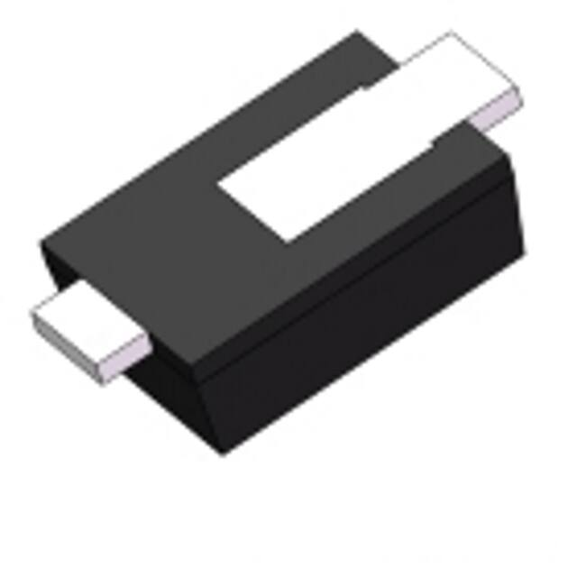


 工商网监
湘ICP备2023018690号
工商网监
湘ICP备2023018690号
