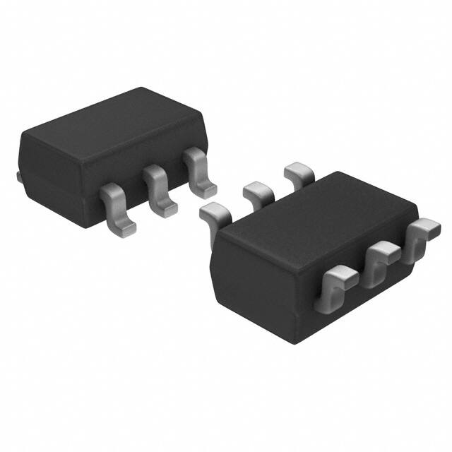
DATASHEET
ISL32613E, ISL32614E
FN7906
Rev.4.01
Sep 27, 2019
±16.5kV ESD Protected, +125°C, 1.8V to 3.6V, Low Power, SOT-23,
RS-485/RS-422 Transmitters
The ISL32613E and ISL32614E are ±16.5kV HBM ESD
protected (7kV IEC61000 contact), 1.8V powered, single
transmitters for differential communication. These drivers
have very low bus currents (±40µA), so they present less than
a 1/8 unit load to the bus. The low bus currents allow more
than 256 transmitters on the network without violating the
RS-485 specification’s 32 unit load maximum and without
using repeaters.
Features
Hot plug circuitry ensures that the Tx outputs remain in a high
impedance state while the power supply stabilizes.
• Specified for +125°C
Both ICs use slew rate limited drivers, which reduce EMI and
minimize reflections from improperly terminated transmission
lines or unterminated stubs in multidrop and multipoint
applications. The ISL32613E is more slew rate limited for data
rates up to 128kbps, while the less limited ISL32614E is
useful for data rates up to 256kbps.
• Low Tx leakage allows >256 devices on the bus
For companion low power single RS-485 receivers, see the
ISL32610E datasheet.
• Pb-Free (RoHS Compliant)
Related Literature
Applications
For a full list of related documents, visit our website:
• Industrial/process control networks
• Wide supply voltage range . . . . . . . . . . . . . . . . . . 1.8V to 3.6V
• Low quiescent supply current. . . . . . . . . . . . . . . . 80µA (max)
- Very low shutdown supply current . . . . . . . . . . . 2µA (max)
• High ESD protection on RS-485 outputs . . . . ±16.5kV HBM
- Class 3 ESD level on all other pins. . . . . . . . . . . >8kV HBM
• Hot plug - Tx outputs remain three-state during power-up
• Slew rate limited for data rates up to 256kbps
• Current limiting and thermal shutdown for driver overload
protection
• 5V tolerant logic inputs
• Space-constrained systems
• ISL32613E and ISL32614E device pages
• Factory automation
• Building environmental control/lighting systems
10m
Truth Table
RD = ∞, CD = 50pF
TRANSMITTING
INPUTS
DYNAMIC (128kbps)
ICC (A)
1m
STATIC
100µ
OUTPUTS
DE (Note 9)
DI
Z
Y
1
1
0
1
1
0
1
0
0
X
High-Z *
High-Z *
NOTE: *Shutdown Mode
10µ
1.8
2.0
2.2
2.4
2.6
2.8
3.0
3.2
3.4
3.6
VCC (V)
FIGURE 1. ISL32613E WITH VCC = 1.8V REDUCES OPERATING
ICC BY A FACTOR OF 177 COMPARED WITH ICC AT
VCC = 3.6V
FN7906 Rev.4.01
Sep 27, 2019
Page 1 of 12
�ISL32613E, ISL32614E
Typical Operating Circuits
1. 8V
1. 8V
100nF
1
100nF
2
VCC
3 RO
1k
VCC
A 5
6 Y
B 4
4 Z
DI 1
DE 3
GND
GND
2
5
ISL32610E
ISL32613E
FIGURE 2. POINT-TO-POINT LINK WITH FIXED ENABLE-PINS
1.8V
1
VCC
10k
1.8V
100nF
100nF
5.6k
A 6
3 RO
5 RE
6 Y
B 4
GND
2
2
VCC
DI 1
4 Z
5.6k
ISL32611E
DE 3
GND
5
ISL32613E
FIGURE 3. POINT-TO-POINT LINK WITH PROGRAMMABLE ENABLE-PINS
FN7906 Rev.4.01
Sep 27, 2019
Page 2 of 12
�ISL32613E, ISL32614E
Ordering Information
PART
MARKING
(Note 4)
PART NUMBER
(Notes 2, 3)
TEMP RANGE
(°C)
TAPE AND REEL
(UNITS) (Note 1)
PACKAGE
(RoHS Compliant)
PKG.
DWG. #
ISL32613EFHZ-T
613F
-40 to +125
3k
6 Ld SOT-23
P6.064
ISL32613EFHZ-T7A
613F
-40 to +125
250
6 Ld SOT-23
P6.064
ISL32614EFHZ-T
614F
-40 to +125
3k
6 Ld SOT-23
P6.064
ISL32614EFHZ-T7A
614F
-40 to +125
250
6 Ld SOT-23
P6.064
NOTES:
1. See TB347 for details about reel specifications.
2. These Pb-free plastic packaged products employ special Pb-free material sets, molding compounds/die attach materials, and 100% matte tin plate
plus anneal (e3 termination finish, which is RoHS compliant and compatible with both SnPb and Pb-free soldering operations). Pb-free products are
MSL classified at Pb-free peak reflow temperatures that meet or exceed the Pb-free requirements of IPC/JEDEC J STD-020.
3. For Moisture Sensitivity Level (MSL), see the ISL32613E and ISL32614E device pages. For more information about MSL, see TB363.
4. SOT-23 “PART MARKING” is branded on the bottom side.
NOTES:
TABLE 1. SUMMARY OF FEATURES AT VCC = 1.8V
PART NUMBER
FUNCTION
DATA RATE
(kbps)
SLEW-RATE
LIMITED?
HOT
PLUG?
TX ENABLED?
(Note 9)
MAXIMUM QUIESCENT
ICC (µA)
LOW POWER
SHUTDOWN?
PIN
COUNT
ISL32613E
1 Tx
128
Yes
Yes
Yes
80
Yes
6 Ld SOT
ISL32614E
1 Tx
256
Yes
Yes
Yes
80
Yes
6 Ld SOT
Pin Configuration
6 LD SOT-23
TOP VIEW
DI 1
VCC 2
DE 3
6 Y
D
5 GND
4 Z
Pin Descriptions
PIN #
PIN
NAME
1
DI
2
VCC
System power supply input (1.8V to 3.6V).
3
DE
Driver output enable. The driver outputs, Y and Z, are enabled by bringing DE high, and are high
impedance when DE is low. If the driver enable function is not needed, connect DE to VCC through a
1kΩ to 2kΩ resistor.
4
Z
5
GND
6
Y
FN7906 Rev.4.01
Sep 27, 2019
FUNCTION
Driver input. A low on DI forces output Y low and output Z high. Similarly, a high on DI forces output Y
high and output Z low.
±16.5kV HBM, ±7kV IEC61000 (contact method) ESD protected inverting differential transmitter
output.
Ground connection.
±16.5kV HBM, ±7kV IEC61000 (contact method) ESD protected noninverting differential transmitter
output.
Page 3 of 12
�ISL32613E, ISL32614E
Absolute Maximum Ratings
Thermal Information
VCC to GND . . . . . . . . . . . . . . . . . . . . . . . . . . . . . . . . . . . . . . . . . . . -0.3V to 7V
Input Voltages
DI, DE . . . . . . . . . . . . . . . . . . . . . . . . . . . . . . . . . . . . . . . . . . . . . -0.3V to 7V
Output Voltages
Y, Z (VCC = 0V or ≥ 2.7V). . . . . . . . . . . . . . . . . . . . . . . . . . . . . . -8V to +13V
Y, Z (VCC = 1.8V, Output Enabled) . . . . . . . . . . . . . . . . . . . . . . . -8V to +3V
Y, Z (VCC = 1.8V, Output Disabled) . . . . . . . . . . . . . . . . . . . . . . -8V to +8V
Short Circuit Duration
Y, Z. . . . . . . . . . . . . . . . . . . . . . . . . . . . . . . . . . . . . . . . . . . . . . . . . . Indefinite
ESD Rating . . . . . . . . . . . . . . . . . . . . . . . . . . . . . see “ESD PERFORMANCE”
Latch-Up (per JESD78, Level 2, Class A). . . . . . . . . . . . . . . . . . . . . . +125°C
JA (°C/W) JC (°C/W)
Thermal Resistance (Typical)
6 Ld SOT-23 Package (Notes 5, 6). . . . . . . .
177
95
Maximum Junction Temperature (Plastic Package) . . . . . . . . . . . +150°C
Maximum Storage Temperature Range . . . . . . . . . . . . . -65°C to +150°C
Pb-Free Reflow Profile. . . . . . . . . . . . . . . . . . . . . . . . . . . . . . . . . . .see TB493
Recommended Operating Conditions
Supply Voltage Range . . . . . . . . . . . . . . . . . . . . . . . . . . . . . . . . . 1.8V to 3.3V
Common-Mode Range; VCC = 1.8V . . . . . . . . . . . . . . . . . . . . . . . . . . . . . ±2V
VCC ≥ 2.7V . . . . . . . . . . . . . . . . . . . . . . . . . . . . . . . . . . . . . . . . -7V to +12V
Temperature Range (F Suffix) . . . . . . . . . . . . . . . . . . . . . -40°C to +125°C
Differential Load (RD); VCC = 1.8V . . . . . . . . . . . . . . . . . . . . . . . . . . . ≥10kΩ
VCC ≥ 2.7V . . . . . . . . . . . . . . . . . . . . . . . . . . . . . . . . . . . . . . . . . . . . . . ≥60Ω
CAUTION: Do not operate at or near the maximum ratings listed for extended periods of time. Exposure to such conditions can adversely impact product
reliability and result in failures not covered by warranty.
NOTES:
5. JA is measured with the component mounted on a high-effective thermal conductivity test board in free air. See TB379 for details.
6. For JC, the “case temp” location is taken at the package top center.
Electrical Specifications
operating temperature range. (Note 7)
PARAMETER
VCC = 1.8V; typical values are at TA = +25°C; unless otherwise specified. Boldface limits apply across the
SYMBOL
TEST CONDITIONS
TEMP
MIN
(°C) (Note 10)
TYP
MAX
(Note 10)
UNIT
DC CHARACTERISTICS
Driver Differential VOUT
Change in Magnitude of Driver
Differential VOUT for Complementary
Output States
Driver Common-Mode VOUT
Change in Magnitude of Driver
Common-Mode VOUT for
Complementary Output States
Logic Input High Voltage (DI, DE)
Logic Input Low Voltage (DI, DE)
VOD
VCC = 1.8V
Full
0.8
0.92
-
V
VCC ≥ 3.15V
Full
2
-
-
V
RL = 54Ω (Figure 4), VCC ≥ 3V
Full
1.5
-
-
V
No Load
Full
1.1
1.45
VCC
V
VOD
RL = 100Ω (Figure 4)
Full
-
0.01
0.2
V
V0C
RL = 100Ω (Figure 4)
Full
-
1.1
1.4
V
VOC
RL = 100Ω (Figure 4)
Full
-
0.01
0.2
V
VCC = 1.8V
Full
1.26
-
-
V
2.7V ≤ VCC ≤ 3.6V
Full
2.2
-
-
V
VCC = 1.8V
Full
-
-
0.4
V
2.7V ≤ VCC ≤ 3.6V
Full
-
-
0.8
V
VIH
VIL
RL = 100Ω (Figure 4)
Logic Input Current
IIN
DI = DE = 0V or VCC (Note 9)
Full
-2
-
2
µA
Output Leakage Current
(Y, Z, Note 9)
IOZ
DE = 0V,
VCC = 0V or 1.8V, or 3.6V
Full
-
0.1
30
µA
Driver Short-Circuit Current,
VO = High or Low (Note 8)
IOS
VO = 7V at VCC = 1.8V
VO = 12V at VCC = 3.6V
Full
-
0.1
40
µA
VO = -7V
Full
-40
-8
-
µA
VCC = 1.8V, DE = VCC, -2V ≤ VO ≤ 2V
Full
-
-
±250
mA
VCC ≥ 2.7V, DE = VCC, -7V ≤ VO ≤ 12V
Full
-
±150
-
mA
DE = VCC = 1.8V, DI = 0V or VCC
Full
-
20
80
µA
DE = VCC, 2.7V ≤ VCC ≤ 3.6V, DI = 0V or VCC
Full
-
100
150
µA
SUPPLY CURRENT
No-Load Supply Current
FN7906 Rev.4.01
Sep 27, 2019
ICC
Page 4 of 12
�ISL32613E, ISL32614E
Electrical Specifications
VCC = 1.8V; typical values are at TA = +25°C; unless otherwise specified. Boldface limits apply across the
operating temperature range. (Note 7) (Continued)
PARAMETER
Shutdown Supply Current
SYMBOL
ISHDN
TEST CONDITIONS
TEMP
MIN
(°C) (Note 10)
TYP
MAX
(Note 10)
UNIT
1.8V ≤ VCC ≤ 3.6V, DE = 0V, DI = 0V or VCC
Full
-
0.01
2
µA
Human Body Model, from bus pins to GND
25
-
±16.5
-
kV
IEC61000 Contact, from bus pins to GND
25
-
±7
-
kV
HBM, per MIL-STD-883 Method 3015
25
-
±8
-
kV
Machine Model
25
-
±400
-
V
VCC = 1.8V
Full
128
-
-
kbps
3V ≤ VCC ≤ 3.6V
Full
256
-
-
kbps
VCC = 1.8V
Full
-
1700
2600
ns
3V ≤ VCC ≤ 3.6V
Full
-
1100
1500
ns
VCC = 1.8V
Full
-
30
200
ns
3V ≤ VCC ≤ 3.6V
Full
-
2
30
ns
VCC = 1.8V
Full
-
1600
2600
ns
ESD PERFORMANCE
RS-485 Pins (Y, Z)
All Pins
DRIVER SWITCHING CHARACTERISTICS (ISL32613E, 128kbps Version)
Maximum Data Rate
Driver Differential Output Delay
Driver Differential Output Skew
Driver Differential Rise or Fall Time
fMAX
tDD
tDSK
tR, tF
CD = 50pF (Figure 5)
CD = 50pF (Figure 5)
CD = 50pF (Figure 5)
3V ≤ VCC ≤ 3.6V
Full
400
960
1500
ns
Driver Enable to Output High
tZH
RL = 500Ω, CL = 50pF, SW = GND (Figure 6)
Full
-
460
800
ns
Driver Enable to Output Low
tZL
RL = 500Ω, CL = 50pF, SW = VCC (Figure 6)
Full
-
460
800
ns
Driver Disable from Output High
tHZ
RL = 500Ω, CL = 50pF, SW = GND (Figure 6)
Full
-
60
250
ns
Driver Disable from Output Low
tLZ
RL = 500Ω, CL = 50pF, SW = VCC (Figure 6)
Full
-
60
250
ns
VCC = 1.8V
Full
256
-
-
kbps
3V ≤ VCC ≤ 3.6V
Full
500
-
-
kbps
RD = ∞, CD = 50pF
(Figure 5)
VCC = 1.8V
Full
-
700
2000
ns
3V ≤ VCC ≤ 3.6V
Full
-
350
500
ns
RD = ∞, CD = 50pF
(Figure 5)
VCC = 1.8V
Full
-
30
200
ns
3V ≤ VCC ≤ 3.6V
Full
-
2
30
ns
VCC = 1.8V
Full
-
1700
2600
ns
3V ≤ VCC ≤ 3.6V
Full
200
350
800
ns
DRIVER SWITCHING CHARACTERISTICS (ISL32614E, 256kbps Version)
Maximum Data Rate
Driver Differential Output Delay
Driver Differential Output Skew
Driver Differential Rise or Fall Time
fMAX
tDD
tDSK
tR, tF
RD = ∞, CD = 50pF
RD = ∞, CD = 50pF
(Figure 5)
Driver Enable to Output High
tZH
RL = 500Ω, CL = 50pF, SW = GND (Figure 6)
Full
-
460
800
ns
Driver Enable to Output Low
tZL
RL = 500Ω, CL = 50pF, SW = VCC (Figure 6)
Full
-
460
800
ns
Driver Disable from Output High
tHZ
RL = 500Ω, CL = 50pF, SW = GND (Figure 6)
Full
-
60
250
ns
Driver Disable from Output Low
tLZ
RL = 500Ω, CL = 50pF, SW = VCC (Figure 6)
Full
-
60
250
ns
NOTES:
7. All currents into device pins are positive; all currents out of device pins are negative. All voltages are referenced to device ground unless otherwise specified.
8. Applies to peak current. See “Typical Performance Curves” on page 7 for more information.
9. If the Driver Enable function is not needed, connect DE to VCC through a 1kΩ to 2kΩ resistor.
10. Compliance to datasheet limits is assured by one or more methods: production test, characterization, and/or design.
FN7906 Rev.4.01
Sep 27, 2019
Page 5 of 12
�ISL32613E, ISL32614E
Test Circuits and Waveforms
VCC
RL/2
DE
Z
DI
VOD
D
Y
RL/2
VOC
FIGURE 4. DC DRIVER TEST CIRCUITS
VCC
DI
50%
50%
0V
tSD2
tSD1
DE
VCC
Z
DI
VOH
OUT (Z)
RD
D
50%
CD
50%
VOL
OUT (Y)
Y
tDDHL
tDDLH
SIGNAL
GENERATOR
DIFF OUT (Y - Z)
90%
50%
10%
tR
-VOD
tF
tDSK = |tDDLH - tDDHL|
tSSK = |tSD1(Y) - tSD2(Y)| OR |tSD1(Z) - tSD2(Z)|
FIGURE 5A. TEST CIRCUIT
+VOD
90%
50%
10%
FIGURE 5B. MEASUREMENT POINTS
FIGURE 5. DRIVER PROPAGATION DELAY AND DIFFERENTIAL TRANSITION TIMES
DE
VCC
Z
DI
500Ω
D
SIGNAL
GENERATOR
VCC
SW
Y
DE
50%
50%
0V
GND
50pF
tZH
tHZ
OUTPUT HIGH
PARAMETER
OUTPUT
DI
SW
tHZ
Y/Z
1/0
GND
tLZ
Y/Z
0/1
VCC
tZH
Y/Z
1/0
GND
tZL
Y/Z
0/1
FIGURE 6A. TEST CIRCUIT
VOH - 0.25V
50%
OUT (Y, Z)
VOH
0V
tLZ
tZL
VCC
OUT (Y, Z)
50%
OUTPUT LOW
VCC
VOL + 0.25V V
OL
FIGURE 6B. MEASUREMENT POINTS
FIGURE 6. DRIVER ENABLE AND DISABLE TIMES
FN7906 Rev.4.01
Sep 27, 2019
Page 6 of 12
�ISL32613E, ISL32614E
Typical Performance Curves
VCC = 1.8V, TA = +25°C; unless otherwise specified.
22
60
DE = VCC
18
50
-40°C
16
14
40
+125°C
12
ICC (µA)
DRIVER OUTPUT CURRENT (mA)
20
RD = 120Ω
10
8
10
4
+25°C
2
0
20
+85°C
6
30
0
0.2
RD = 1kΩ
0.4
0.6
0.8
1.0
1.2
1.4
DIFFERENTIAL OUTPUT VOLTAGE (V)
1.6
0
-40
1.8
10
35
60
85
110 125
TEMPERATURE (°C)
FIGURE 7. DRIVER OUTPUT CURRENT vs DIFFERENTIAL OUTPUT
VOLTAGE
10m
-15
FIGURE 8. STATIC SUPPLY CURRENT vs TEMPERATURE
10m
RD = ∞, CD = 50pF
RD = ∞, CD = 50pF
128kbps
128kbps
256kbps
1m
1m
100µ
56kbps
ICC (A)
ICC (A)
56kbps
100µ
9.6kbps
9.6kbps
10µ
1.8
2.0
2.2
2.4
2.6
2.8
3.0
3.2
3.4
10µ
1.8
3.6
2.0
2.2
2.4
VCC (V)
2.6
2.8
3.0
3.2
3.4
VCC (V)
FIGURE 9. ISL32613E DYNAMIC SUPPLY CURRENT vs SUPPLY
VOLTAGE AT DIFFERENT DATA RATES
FIGURE 10. ISL32614E DYNAMIC SUPPLY CURRENT vs SUPPLY
VOLTAGE AT DIFFERENT DATA RATES
110
100
OUTPUT CURRENT (mA)
90
-40°C
80
70
60
+25°C
50
40
30
+125°C
20
10
0
-10
Y OR Z = LOW
+125°C
-20
Y OR Z = HIGH
-30
-2.0
-1.5
-1.0
-0.5
0
0.5
OUTPUT VOLTAGE (V)
1.0
1.5
2.0
FIGURE 11. DRIVER OUTPUT CURRENT vs SHORT-CIRCUIT VOLTAGE
FN7906 Rev.4.01
Sep 27, 2019
3.6
Page 7 of 12
�ISL32613E, ISL32614E
DI
1.5
1.5
1
1
0.5
Y-Z
0
-0.5
-1
-1.5
-0.5
-1
0
DRIVER INPUT (V)
2
DI
1.5
1.5
1
1
0.5
Y-Z
0
-0.5
-1
-1.5
TIME (400ns/DIV)
FIGURE 14. ISL32614E DRIVER WAVEFORMS, LOW-TO-HIGH
Application Information
Driver Features
The ISL32613E and ISL32614E transmitters are differential
output devices that operate with VCC as low as 1.8V and up to
3.6V. The devices are RS-485 compliant with VCC ≥ 3V, but
significant power savings are obtained by operating at VCC =
1.8V.
The transmitter outputs are tri-statable with the active high DE
input. If the Tx enable function is not needed, tie DE to VCC
through a 1kΩ to 2kΩ resistor. Outputs are slew rate limited to
minimize EMI and to reduce reflections in unterminated or
improperly terminated networks.
FN7906 Rev.4.01
Sep 27, 2019
TIME (1µs/DIV)
RD = 10kΩ, CD = 50pF
DRIVER OUTPUT (V)
DRIVER OUTPUT (V)
DI
Y-Z
0
FIGURE 13. ISL32614E DRIVER WAVEFORMS, HIGH-TO-LOW
FIGURE 12. ISL32613E DRIVER WAVEFORMS, LOW-TO-HIGH
RD = 10kΩ, CD = 50pF
0
0.5
-1.5
TIME (1µs/DIV)
2
DRIVER INPUT (V)
0
RD = 10kΩ, CD = 50pF
DRIVER OUTPUT (V)
DRIVER OUTPUT (V)
DI
2
2
0
DRIVER INPUT (V)
RD = 10kΩ, CD = 50pF
VCC = 1.8V, TA = +25°C; unless otherwise specified. (Continued)
DRIVER INPUT (V)
Typical Performance Curves
0.5
Y-Z
0
-0.5
-1
-1.5
TIME (400ns/DIV)
FIGURE 15. ISL32614E DRIVER WAVEFORMS, HIGH-TO-LOW
1.8V Operation
The ISL32613E and ISL32614E operate with VCC as low as 1.8V.
When coupled with the ISL32610E or ISL32611E 1.8V receivers,
they provide a differential communication link optimized for very
low power and for slow data rates. Figures 9 and 10 illustrate the
static and dynamic power savings from using these transmitters
at low supply voltages. With VCC = 1.8V rather than 3.3V, using
the ISL32613E at 128kbps reduces the operating supply current
from 9.9mA to 56µA (a factor of 177).
5.5V Tolerant Logic Pins
The logic input pins (DI and DE) contain no ESD or parasitic
diodes to VCC, so they withstand input voltages exceeding 5.5V,
regardless of the VCC voltage.
Page 8 of 12
�ISL32613E, ISL32614E
Hot Plug Function
Driver Overload Protection
When a piece of equipment powers up, there is a period of time
during when the processor or ASIC driving the RS-485 control line
(DE) is unable to ensure that the RS-485 Tx outputs are kept
disabled. If the equipment is connected to the bus, a driver
activating prematurely during power-up may crash the bus. To
avoid crashes, these transmitters incorporate a hot plug function.
During power-up, circuitry monitoring VCC ensures that the Tx
outputs remain disabled for a period of time, regardless of the state
of DE. The disabled Tx outputs allow the processor/ASIC a chance to
stabilize and drive the control lines to the proper states.
The driver output stages incorporate short-circuit, current-limiting
circuitry that ensures that the output current never exceeds the
RS-485 specification over a ±2V (-7V to +12V for VCC ≥ 2.7V)
common mode voltage range.
ESD Protection
All pins on these devices include Class 3 (8kV) Human Body
Model (HBM) ESD protection structures, but the driver outputs
incorporate advanced structures that allow them to survive ESD
events in excess of ±16.5kV HBM and ±7kV to the IEC61000
contact test method. The RS-485 pins are particularly
vulnerable to ESD damage because they typically connect to an
exposed port on the exterior of the finished product. Touching
the port pins or connecting a cable can cause an ESD event that
destroy unprotected ICs. The new ESD structures protect the
device whether it is powered up or not, and without degrading
the common-mode range. This built-in ESD protection
eliminates the need for board-level protection structures (for
example, transient suppression diodes) and the associated,
undesirable capacitive load they present.
The ISL32613E and ISL32614E's thermal shutdown feature
disables the drivers whenever the die temperature becomes
excessive in the event of a major short-circuit condition. Thermal
shutdown eliminates power dissipation, allowing the die to cool.
The drivers automatically reenable after the die temperature drops
by about +20°C. If the condition persists, the thermal
shutdown/reenable cycle repeats until the fault is cleared.
Low Power Shutdown Mode
Th BiCMOS transmitters use a fraction of the power required by
its bipolar counterparts, but they also include a shutdown feature
that reduces the already low quiescent ICC to a 10nA trickle.
These devices enter shutdown whenever the driver disables
(DE = GND).
Die Characteristics
SUBSTRATE POTENTIAL (POWERED UP):
GND
PROCESS:
Si Gate BiCMOS
FN7906 Rev.4.01
Sep 27, 2019
Page 9 of 12
�ISL32613E, ISL32614E
Revision History
The revision history provided is for informational purposes only and is believed to be accurate, but not warranted. Please visit our website to ensure you
have the latest revision.
DATE
REVISION
Sep 27, 2019
FN7906.4.01
Feb 14, 2019
FN7906.4
Updated both Typical Operating Circuits.
Updated links throughout document.
Updated disclaimer.
Jun 12, 2018
FN7906.3
Added Related Literature section on page 1.
Updated Ordering information table by switching Notes 1 and 2 and adding the tape and reel units column.
Removed military temperature range from Features on page 1.
Removed 55°C curves from Figures 7 and 11 on page 8.
Removed About Intersil section and added Renesas disclaimer.
Jul 27, 2015
FN7906.2
Ordering Information Table on page 3: Removed part numbers ISL32614EMHZ-T and ISL32614EMHZ-T7A.
Recommended Operating Conditions table on page 4: Removed the line referencing “M Suffix”.
Replaced “Product” section with “About Intersil” on page 10.
May 2, 2012
FN7906.1
Page 1, “Features” - changed “Specified for +125°C Operation” to “Specified for +125°C or Full Mil
Temperature Operation”. Also changed Figure 1 title.
Page 2, added new part “ISL32614EMHZ-T” to the “Ordering Information”.
Page 4, changed “Y, Z (VCC = 1.8V)” to “Y, Z (VCC = 1.8V, Output Enabled)” and added “Y, Z (VCC = 1.8V, Output
Disabled)... -8V to +8V” under the “Absolute Maximum Rating”. Also added “(F Suffix)” and “(M Suffix)...-55°C to
+125°C” under the “Recommended Operating Conditions”.
Page 8, replaced Figure 7 and added -55°C curve to Figure 11 under the “Typical Performance Curves”.
Aug 30, 2011
FN7906.0
Initial Release
FN7906 Rev.4.01
Sep 27, 2019
CHANGE
Replaced Figures 2 and 3.
Removed Note on page 2.
Page 10 of 12
�ISL32613E, ISL32614E
Package Outline Drawing
For the most recent package outline drawing, see P6.064.
P6.064
6 LEAD SMALL OUTLINE TRANSISTOR PLASTIC PACKAGE
Rev 4, 2/10
0-8°
1.90
0.95
0.08-0.22
D
A
6
5
4
2.80
PIN 1
INDEX AREA
1.60 +0.15/-0.10
3
3
(0.60)
1
2
3
0.20 C
2x
0.40 ±0.10
B
SEE DETAIL X
3
0.20 M C A-B D
END VIEW
TOP VIEW
10° TYP
(2 PLCS)
2.90 ±0.10
3
1.15 +0.15/-0.25
C
0.10 C
SEATING PLANE
0.00-0.15
SIDE VIEW
(0.25)
GAUGE
PLANE
1.45 MAX
DETAIL "X"
0.45±0.1
4
(0.95)
(0.60)
(1.20)
(2.40)
NOTES:
1.
Dimensions are in millimeters.
Dimensions in ( ) for Reference Only.
2.
Dimensioning and tolerancing conform to ASME Y14.5M-1994.
3.
Dimension is exclusive of mold flash, protrusions or gate burrs.
4.
Foot length is measured at reference to gauge plane.
5.
Package conforms to JEDEC MO-178AB.
TYPICAL RECOMMENDED LAND PATTERN
FN7906 Rev.4.01
Sep 27, 2019
Page 11 of 12
�1RWLFH
��
'HVFULSWLRQV�RI�FLUFXLWV��VRIWZDUH�DQG�RWKHU�UHODWHG�LQIRUPDWLRQ�LQ�WKLV�GRFXPHQW�DUH�SURYLGHG�RQO\�WR�LOOXVWUDWH�WKH�RSHUDWLRQ�RI�VHPLFRQGXFWRU�SURGXFWV�
DQG�DSSOLFDWLRQ�H[DPSOHV��


 工商网监
湘ICP备2023018690号
工商网监
湘ICP备2023018690号
